Modelling with AutoCAD 2004 phần 8 doc
Bạn đang xem bản rút gọn của tài liệu. Xem và tải ngay bản đầy đủ của tài liệu tại đây (762.1 KB, 35 trang )
The edge primitives 235
4 Select the CHAMFER icon from the Modify toolbar and:
prompt Select first line or [Polyline/Distance
respond pick any line on top surface
prompt Base surface selection
and a) one face of the cube will be highlighted
b) it will be a ‘side’ or the ‘top’
prompt Enter surface selection option [Next/OK (current)]
respond a) right-click/enter if top face is highlighted
b) enter NϽRϾ if side face is highlighted to highlight the top face then
right-click/enter
prompt Specify base surface chamfer distance
enter 15 ϽRϾ
prompt Specify other surface chamfer distance
enter 25 ϽRϾ
prompt Select an edge or [Loop]
respond a) pick any three sides on top surface
b) right-click/enter
5 The top surface will be chamfered at the selected three edges
6 Note: entering L for loop will allow all edges to be chamfered with a single pick
7 Select the FILLET icon from the Modify toolbar and:
prompt Select first object or [Polyline/Radius/Trim]
respond pick any line on the base surface of the cube
prompt Enter fillet radius
enter 20 ϽRϾ
prompt Select edge or [Chain/Radius]
respond pick any three edges of the base then right-click
8 The base of the cube will be filleted at the three selected edges and displayed as Fig.
34.1(a).
Example 2 – a cylinder solid
1 Erase the cube and at the command line enter ISOLINES ϽRϾ and check the value is 12
2 Use the CYLINDER icon to create a cylinder with:
a) centre: 0,0,0
b) radius: 50
c) height: 100
3 Zoom-centre about 0,0,50 at 200 magnification
4 Select the CHAMFER icon and:
prompt Select first line or
respond pick the top surface circle edge
prompt Base surface selection
then Enter surface selection option
respond ϽRETURNϾ as the required surface is highlighted
prompt Specify base surface chamfer distance
enter 15 ϽRϾ
prompt Specify other surface chamfer distance
enter 15 ϽRϾ
prompt Select an edge or
respond pick top circle edge then right-click/enter
236 Modelling with AutoCAD 2004
5 The top of the cylinder is chamfered with the entered values
6 Select the FILLET icon and:
prompt Select first object
respond pick bottom circle of cylinder
prompt Enter fillet radius
enter 25 ϽRϾ
prompt Select an edge
respond right-click as bottom edge already selected
7 The cylinder is filleted at the base
8 The chamfer/fillet effect on the cylinder is displayed as Fig. 34.1(b).
Example 3 – The edge primitives on a solid composite
1 Erase the cylinder model and with MVLAY1 tab, UCS BASE, layer MODEL and the
lower left viewport active, create four primitives with:
box cylinder box cylinder
corner: 0,0,0 centre: 75,60,0 corner: 50,0,40 centre: 150,0,0
length: 150 radius: 40 length: 60 radius: 35
width: 120 height: 100 width: 150 height: 120
height: 100 colour: green height: 40 colour: magenta
colour: red colour: blue
2 In all viewports, zoom-centre about 75,60,50 at 200 magnification in the 3D viewport
and 150 magnification in the other viewports
3 Subtract the green, blue and magenta primitives from the red box and note the ‘inter-
penetration’ effect
4 Select the FILLET icon and:
a) pick the top circle of the green object
b) enter a radius of 15
c) select an edge and right-click/enter
5 The top edge of the cylinder is filleted ‘outwards’ and is red. Why is the fillet red and
not green, as the selected object to be filleted was green?
6 Select the CHAMFER icon and:
a) pick the top long front edge of the red box
b) press ϽRETURNϾ if the front vertical face is highlighted or N ϽRϾ until front
vertical face is highlighted then right-click/enter
c) enter base surface distance of 10
d) enter other surface distance of 5
e) pick the four front edges of the blue primitive then right-click/enter
f) failure while chamfering message displayed?
7 Repeat the CHAMFER command as step 6, but enter both chamfer distances as 5
8 The blue box primitive will then be chamfered in red – not blue?
9 Now fillet the top curve of the magenta cylinder with a radius of 20 – paper space
zoom of 3D viewport recommended
10 The completed model is displayed as Fig. 34.2
The edge primitives 237
11 With the model tab active and a SE Isometric viewpoint, Gouraud shade and 3D orbit
the model. Note the effect of the two fillet radii on the top surface
12 The model can be saved if required, but will not be used again.
A practical use for fillet/chamfer with solids
Before leaving this chapter, we will investigate a practical use of the fillet and chamfer
commands with solids so:
1 Erase the composite on the screen and ensure UCS BASE, layer MODEL and lower
left viewport active. Refer to Fig. 34.3
2 Create the following three box primitives:
box1 box2 box3
corner 0,0,0 0,0,100 10,100,10
length 100 10 90
width 100 100 Ϫ10
height 10 Ϫ90 90
3 Union the three boxes and copy the unioned composite from: 0,0,0 to 100,100,0
4 Scale the copied composite about the point 100,100 by 0.75
5 Change the viewpoint in the 3D viewport with VPOINT-ROTATE and angles of
300 and 30
6 Zoom-centre in each viewport about the point 80,80,50 for 225 magnification
Figure 34.2 Chamfered and filleted composite.
238 Modelling with AutoCAD 2004
7 In paper space zoom in on the 3D viewport then model space
8 Select the FILLET icon and:
prompt Select first object
respond pick edge 12
prompt Enter fillet radius and enter: 25 ϽRϾ
prompt Select an edge
respond pick edges 12,23 and 24 then right-click/enter
9 Select the CHAMFER icon and:
prompt Select first line
respond pick edge AB
prompt Enter surface selection option
respond a) enter N ϽRϾ until horizontal surface is highlighted
b) right-click/enter
prompt Specify base surface chamfer distance and enter: 15 ϽRϾ
prompt Specify other surface chamfer distance and enter: 25 ϽRϾ
prompt Select an edge
respond pick edges AB and BC then right-click/enter
10 The two composites will be filleted and chamfered at the selected edges
11 Questions
a) Is it possible to fillet more that three edges at the one time?
b) Can a chamfer be added to three adjacent surfaces?
This completes the edge primitive exercise.
Figure 34.3 Practical use for chamfer/fillet.
Summary
1 Primitives and solids can be chamfered and filleted with the ‘normal’ CHAMFER and
FILLET commands
2 Solids and primitives can be chamfered/filleted:
a) inwards if a primitive
b) outwards if a ‘hole’
3 Individual edges can be chamfered and filleted
4 The chamfer command has a LOOP option allowing a complete surface to be chamfered
5 The fillet command has a CHAIN option allowing a complete surface to be filleted
6 Error messages will be displayed if the chamfer distances or the fillet radius are too
large for the model being modified, and the command line will display:
a) Failed to perform blend
b) Failure while chamfering/Filleting.
Assignment
This activity requires a cube to be chamfered to give a ‘truncated pyramid’. The model
will be used in a later activity, so ensure that it is saved.
Activity 19: Penetrated pyramid of MACFARAMUS.
One of MACFARAMUS’s model pyramids (well the chief digger said it was a model
pyramid) was unearthed from the desert and basically consisted of four primitives:
a) a cube of side 200 with a chamfer effect
b) a cylinder with radius 25, positioned vertically through the cube centre
c) a square box of side 50, positioned horizontally through the cube centre
d) a sphere of radius 60, its centre being 30 above the centre of the top surface
You have to create this model and the suggested approach is:
1 Position the cube (red) with corner at 0,0,0
2 Position the square (blue) sided box using the Centre option
3 Position the cylinder (green)
4 Position the sphere (magenta)
5 Chamfer the cube to give a square topped pyramid, the chamfer distances being 50 for
the top and 180 for the sides
6 Subtract the box, cylinder and sphere from the pyramid
7 Chamfer both open ends of the box with chamfer distances of 10
8 Fillet both ends of the cylinder with a radius of 10
9 Save the composite as MODR2004\MODCOMP.
The edge primitives 239
AutoCAD 2004 allows solid primitives and composites to be edited, the commands
being activated from the:
a) menu bar with Modify-Solids Editing
b) Solids Editing toolbar
The editing facilities available are:
1 Boolean: union, subtraction, intersection
2 Faces: extrude, move, offset, delete, rotate, taper, color, copy
3 Edges: color, copy
4 Body: imprint, clean, separate, shell, check
The Boolean editing features have been used in the creation of the previous compos-
ites, and in this chapter we will investigate some of the other editing features.
Solids editing Example 1
1 Open your SOLA3 template file and refer to Fig. 35.1 which only displays the 3D
viewport. Display the Solids, Solids Editing and Object Snap toolbars.
Chapter 35
Solids editing
Figure 35.1 Solids editing Example 1 – 3D viewport with hide.
2 Make the Model tab active and with layer MODEL current, UCS BASE create the
following:
a) Box: corner at 0,0,0 with L: 150, W: 120, H: 100, colour: red
b) Cylinder: centre at 100,80,0, R: 30, H: 150, colour: blue
3 Draw a polygon with eight sides, centred on 75,0,0 and inscribed in a 30 radius circle
4 Solid extrude this polygon for a height of 150 with 0 taper. Change the extruded
primitive colour to green
5 Subtract the blue cylinder and green extrusion from the red box
6 Pan the composite to suit – Fig. 35.1(a)
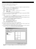
7 Select the OFFSET FACES icon from the Solids Editing toolbar and:
prompt Select faces or [Undo/Remove]
respond pick any pt1 on side surface then right-click/enter
prompt Specify the offset distance
enter 50 ϽRϾ
prompt Enter a face editing option and enter: X ϽRϾ
prompt Enter a solids editing option and enter: X ϽRϾ
and selected face is offset as Fig. 35.1(b)
8 Select the EXTRUDE FACES icon from the Solids Editing toolbar and:
prompt Select faces or [Undo/Remove]
respond pick any pt2 on the top surface then right-click/enter
prompt Specify height of extrusion or [Path]
enter 80 ϽRϾ
prompt Specify angle of taper for extrusion
enter 5 ϽRϾ
prompt Enter a face editing option and enter: X ϽRϾ
prompt Enter a solids editing option and enter: X ϽRϾ
and top surface of model is extruded as Fig. 35.1(c)
note colour and taper of extruded cylinder and polygon
9 Draw a polyline using:
Start point: 150,120
Next point: @100,0
arc option with arc endpoint: @150, Ϫ150
line option with line endpoint: @100,0
Next point: right-click/enter
10 Zoom-all and pan the model to suit
11 Menu bar with Modify-Solids Editing-Extrude Faces and:
prompt Select faces or [Undo/Remove]
respond pick any pt3 on right face then right-click/enter
prompt Specify height of extrusion or [Path]
enter P ϽRϾ – the path option
prompt Select extrusion path
respond pick any point on polyline
prompt Enter a face editing option and enter: X ϽRϾ
prompt Enter a solid editing option and enter: X ϽRϾ
12 The selected face is extruded along the polyline path as Fig. 35.1(d)
13 Pan the model to suit
Solids editing 241
242 Modelling with AutoCAD 2004
14 Select the TAPER FACES icon from the Solids Editing toolbar and:
prompt Select faces or [Undo/Remove]
respond pick any pt4 on top surface then right-click/enter
prompt Specify the base point
respond Endpoint icon and pick pt5
prompt Specify another point along the axis of tapering
respond Endpoint icon and pick pt6
prompt Specify the taper angle and enter: 12 ϽRϾ
prompt Enter a face editing option and enter: X ϽRϾ then X ϽRϾ
15 The selected top surface will be tapered as Fig. 35.1(e)
16 Menu bar with Modify-Solid Editing-Rotate Faces and:
prompt Select faces or [Undo/Remove]
respond pick any pt7 on face indicated then right-click/enter
prompt Specify an axis point or [Axis by object
respond Endpoint icon and pick pt8
prompt Specify the second point on the rotation axis
respond Endpoint icon and pick pt9
prompt Specify a rotation angle
enter 15 ϽRϾ
prompt Enter a face editing option and enter: X ϽRϾ and X ϽRϾ
17 The selected face is rotated about the selected side as Fig. 35.1(f)
18 Shade and 3D orbit the model then save if required
19 This exercise is now complete.
Solids editing Example 2
1 Open your SOLA3 template file and refer to Fig. 35.2. Display the Solids, Solids
Editing and Object Snap toolbars.
2 With Model tab active, layer MODEL current, UCS BASE create the following two
primitives:
a) Box: corner at 0,0,0, cube option with length 200, colour red
b) Cone: centre at 0,100,100; radius 80; Apex at @300,0 and colour green
3 Subtract the green cone from the red box and pan to suit then alter the viewpoint to
suit – Fig. 35.2(a). Note that Fig. 35.2 only displays the 3D viewport.
4 The options for this example are given as a series of simple steps which you should be
able to follow:
1. Offset faces
a) pick face 1
b) distance: 75 – Fig. 35.2(b)
2. Rotate faces
a) pick face 2
b) axis with endpoints 3 and 4 (in order given)
c) angle 45 – Fig. 35.2(c)
3. Extrude faces
a) pick face 5
b) height: 100 with taper: 0 – Fig. 35.2(d)
4. Move faces
a) pick face 6
b) base point at point 7
c) second point: @0,0,85 – Fig. 35.2(e)
Solids editing 243
5. Taper faces
a) pick face 8
b) axes points 9 and 10
c) taper angle: 65 – Fig. 35.2(f)
6. Rotate faces
a) pick face 11
b) axis with endpoints 12 and 13 (in order given)
c) angle 35 – Fig. 35.2(g)
7. Extrude faces
a) pick face 14
b) height of extrusion: 150
c) taper angle: 10 – Fig. 35.2(h)
This completes the second example which can be saved if required.
Note
1 The two examples have concentrated on the faces editing options
2 It is sometimes difficult to select a face for the solids editing options, and it is some-
times easier to select an edge. As an edge ‘belongs’ to two adjacent faces, the
unwanted face can easily be removed from the ‘selection’ with the ‘R’ entry.
3 The solids editing command allows the user repetitive options, i.e. when one option
has been completed, the command is still active. The UNDO option is very useful.
4 The solids editing command is exited with two X ϽRϾ or ESC.
Figure 35.2 Solids editing Example 2 – 3D viewport without hide.
244 Modelling with AutoCAD 2004
Solids editing Example 3
1 Open your SOLA3 template file and refer to Fig. 35.3. Display suitable toolbars.
2 With the Model tab active, layer MODEL current, UCS BASE, create the following:
a) Box: corner at 0,0,0 with cube option with length 100
b) Cylinder: centre at 0,0,100; radius: 50; height: 20
c) Cylinder: centre at 100,50,100; radius: 30; height: Ϫ50
d) Subtract the second cylinder from the box
e) Zoom and pan to suit – Fig. 35.3(a)
3 Select the IMPRINT icon from the Solids Editing toolbar and:
prompt Select a 3D solid
respond pick the cube
prompt Select an object to imprint
respond pick the R50 cylinder
prompt Delete the source object <N>
enter Y ϽRϾ
prompt Select an object to imprint
respond ϽRϾ – no more objects to imprint
prompt body editing options and enter: X ϽRϾ
prompt solids editing options and enter: X ϽRϾ
4 The cylinder outline is imprinted on the cube – Fig. 35.3(b)
5 With the EXTRUDE FACES option:
a) pick face 1
b) enter an extrusion height of 100
c) enter a taper angle of 5 – Fig. 35.3(c)
Figure 35.3 Solids editing Example 3.
Solids editing 245
6 Select the COPY FACES icon from the Solids Editing toolbar and:
prompt Select faces
respond pick face 2 then right-click/enter
prompt Specify a base point or displacement
respond Endpoint icon and pick pt3
prompt Specify a second point of displacement
enter @50,0,150 ϽRϾ then exit the command
7 The selected face is copied as Fig. 35.3(d)
8 Erase all objects from the screen and create two primitives:
a) cylinder: centre 0,0,0; radius: 30; height: 100
b) cone: centre 0,0,200; base radius: 100; height: Ϫ150
c) union the cone and cylinder – Fig. 35.3(e)
9 Select the SHELL icon from the Solids Editing toolbar and:
prompt Select a 3D solid
respond pick any point on the composite then right-click/enter
prompt Enter the shell offset distance
enter 15ϽRϾ
then XϽRϾ and XϽRϾ
10 The cylinder/cone is offset by 15 in ‘all directions’ – Fig. 35.3(f)
11 Hide the model then regen
12 With the EXTRUDE FACES icon:
a) pick any point on the ‘top face’
b) extrusion height: Ϫ15
c) angle of taper: 0 – Fig. 35.3(g)
13 Repeat the extrude faces command and:
a) pick any point 4 on the ‘new rim’ of the composite
b) extrusion height: 150
c) angle of taper: 0 – Fig. 35.3(h)
This completes the third solids editing example.
Other solids editing options
Not all of the solids editing options have been used in the worked examples. The fol-
lowing is a brief description of those not considered:
a) Clean: removes all redundant edges and vertices, e.g. imprinted edges
b) Separate: separates 3D solid objects with disjointed volumes into independent 3D
objects. It DOES NOT separate composites created by Boolean operations into the
original primitives.
c) Check: confirms that a selected object is a valid ACIS solid
d) Color Edges/Faces: a very useful option as it allows individual edges and faces to be
coloured, i.e. a cube could be created on layer MODEL (red) and the six faces of the
cube assigned different colours
e) Copy Edges/Faces: should be obvious
f) Delete faces: allows faces of a model to be deleted, but the option has obvious
limitations. Useful with fillet/chamfer edges.
Solids editing errors
When a solids editing option is activated and completed, the command line will display:
a) Solid validation started
b) Solid validation completed
Solids editing may not always work due to the model selected or the option which has
been activated. Typical error messages which are displayed include:
1 No solution for an edge
2 No solution for a vertex
3 No loop through new edges and vertices
4 Could not taper surface as requested
5 Improper edge/edge intersection
6 Gap cannot be filled
If an error message is obtained, then the active option cannot be performed on the
selected object. Try again.
Summary
1 Solids editing allows the user several options
2 These options can result in very interesting and complex models which may be diffi-
cult to achieve from basic primitives
3 The solids editing options are divided into four categories:
a) Boolean operations
b) Face options
c) Edge options
d) Body options
4 Solid editing options which cannot be performed result in an error message being
displayed
5 The solids editing command allows repetitive entries and has an undo option.
246 Modelling with AutoCAD 2004
A region is a closed 2D shape created from lines, circles, arcs, polylines, splines, etc.
and can be used with the solid extrude and revolve command to create composites.
When created, a region has certain characteristics:
● it is a solid of zero thickness
● it is coplaner, i.e. must be created on the one plane
● it consists of loops – outer and inner
● the loops must be continuous closed shapes
● every region has one outer loop
● there may be several inner loops
● inner loops must be in the same plane as the outer loop
● regions can be created with the BOUNDARY command
● regions can be used with the solid EXTRUDE and REVOLVE command
Regions allow the user another method for creating solid models and very complex
models can be created with regions. They can also be used when hatching is to be
added to a sectioned model and when details, e.g. a true shape, is to be extracted from
a model.
Example 1 – a splined shaft
1 Open your A3SOL template file as normal and display suitable toolbars
2 Ensure the DELOBJ system variable is set to 0
3 Refer to Fig. 36.1 (which only displays the 3D viewport) and create the layout from
three circles having diameters 120, 40 and 16. The actual layout is your design but:
a) use the 0,0 point as indicated
b) polar array the 16 diameter circle
4 Zoom-centre about 0,0,40 at 200 magnification – all viewports
5 Select the SUBTRACTION icon from the Solids Editing toolbar, pick the largest circle
then right-click and:
prompt No solids or regions selected
6 Select the REGION icon from the Draw toolbar and:
prompt Select objects
respond pick all circles then right-click
prompt 13 loops extracted
13 Regions created
Chapter 36
Regions
7 Menu bar with Modify-Solids Editing-Subtract and:
prompt Select solids or regions to subtract from
Select objects
respond pick the largest circle then right-click
prompt Select solids or regions to subtract
Select objects
respond pick the 12 smaller circles then right-click
and the region is created as Fig. 36.1(a)
8 At this stage save as MODR2004\REGEX for the next exercise
9 With the lower left viewport active select the EXTRUDE icon from the Solids toolbar and:
a) objects: pick the region
b) height: 100
c) taper angle: 0 – Fig. 36.1(b)
d) hide and shade
10 Undo the hide, shade and extrude effects, then use the EXTRUDE icon with the
following entries:
a) height: 100, taper angle: 3 – Fig. 36.1(c). Undo effect
b) height: 100, taper angle: Ϫ3 – Fig. 36.1(d)
11 This exercise does not need to be saved.
Example 2 – a revolved component
1 Open drawing file MODR2004\REGEX saved from the previous exercise with UCS
BASE – Fig. 36.2(a) which again only displays the 3D viewport
248 Modelling with AutoCAD 2004
Figure 36.1 Region Example 1 – an extruded component.
2 Menu bar with Tools-New UCS-Origin and:
prompt Origin point<0,0,0>
enter ؊100,؊100,0 ϽRϾ
3 Zoom-centre about 150,0,0 at 250 magnification
4 Select the REVOLVE icon from the Solids toolbar and:
prompt Select objects
respond pick the region then right-click
prompt Specify start point for axis of revolution or define
axis by
enter X ϽRϾ – the X axis option
prompt Specify angle of revolution
enter ؊90 ϽRϾ
then pan model to suit and hide – Fig. 36.2(b)
5 Undo the hide and revolve effect to leave the original region
6 Using the REVOLVE icon:
a) pick the region then right-click
b) enter Y as the axis if revolution
c) enter 180 as the angle
d) pan and hide – Fig. 36.2(c)
e) undo the hide and revolve effect
7 Draw a line from: 0,0,0 to: @0,0,100
Regions 249
Figure 36.2 Region Example 2 – a revolved component.
8 Menu bar with Modify-3D Operation-Rotate 3D and:
a) pick the region then right-click
b) enter X ϽRϾ as the axis
c) enter 100,100,0 as a point on the axis
d) enter 90 as the rotation angle
9 With the REVOLVE icon:
a) pick the rotated region the right-click
b) enter O ϽRϾ – object option
c) pick lower end of vertical line
d) enter 240 as the angle of revolution
e) pan to suit then hide – Fig. 36.2(d)
10 This completes the second exercise. Save if required.
Example 3 – using a boundary
1 Open your A3SOL template file as normal and refer to Fig. 36.3
2 Draw three circles:
a) centre: 50,0, radius: 50
b) centre: 0,50, radius: 60
c) centre: 75,75, radius: 75
4 Make a new layer: BND, colour blue and current
250 Modelling with AutoCAD 2004
Figure 36.3 Region Example 3 – created from a boundary.
5 Zoom-centre about 50,50,50 at 200 magnification
6 Menu bar with Draw-Boundary and:
prompt Boundary Creation dialogue box – Fig. 36.4
respond 1. pick Object type: Region
2. pick Pick Points
prompt Select internal point
respond pick a point indicated in Fig. 36.3
prompt Selecting everything
Selecting everything visible
Analyzing the selected data
Analyzing internal islands
then Select internal point
respond right-click
prompt 1 loop extracted
1 Region created
BOUNDARY created 1 region
7 Erase the three circles to leave the blue region – Fig. 36.3(a)
8 Using the EXTRUDE icon:
a) pick the blue boundary region then right-click
b) enter a height of 125
c) enter a taper angle of 2
d) hide the model – Fig. 36.3(b)
9 Undo the hide and extrude effects to leave the blue region
10 With the REVOLVE icon:
a) select the blue region then right-click
b) enter Y as the axis of revolution
c) enter 270 as the angle of revolution
d) hide – Fig. 36.3(c)
Regions 251
Figure 36.4 The Boundary Creation dialogue box.
11 Undo the hide and revolve effect
12 Restore UCS FRONT, and with layer MODEL current draw a polyline with:
Start point: 0,0
Next point: @0,100
Next point: arc option with endpoint: @Ϫ200,0
Next point: arc endpoint: @120,0
Next point: arc endpoint: @Ϫ60,0 then right-click/enter
13 Restore UCS BASE and make layer BND current
14 With the EXTRUDE icon:
a) select the blue region
b) enter P ϽRϾ for the path option
c) pick the red polyline
d) pan to suit
d) hide to give Fig. 36.3(d)
15 The exercise is complete, save?
16 Note:
Although this exercise has been completed using the Boundary command, it could
have also been completed by making the three circles into regions and then using the
Boolean intersection command.
Summary
1 A region is created from closed shapes, e.g. polylines, arcs, circles, ellipses, etc.
2 Regions can be created with the BOUNDARY command
3 Regions consist of loops and all regions must have an outer loop. There can be several
inner loops.
4 Regions can be extruded and revolved
5 All parts of a region are extruded/revolved to the same height or angle of revolution
6 Regions are extruded along the Z axis of the current UCS. The height of the extrusion
can be positive or negative.
7 Regions can be extruded along a path.
252 Modelling with AutoCAD 2004
Assignment
This activity requires a region to be created from circles, copied, scaled and then
extruded to different heights.
Activity 20: Ratchet mechanism of MACFARAMUS.
While digging in a water bed outside the city of CADOPOLIS, a device was discovered
which was thought to be a ratchet mechanism for a primitive type of waterwheel.
This mechanism has three distinct ‘parts’ to it, each having the same shape.
Using the reference sizes given, create the outline from circles, convert these circles
into regions, then subtract the smaller circles from the larger. The other parts of the
mechanism are scaled by 0.85 and 0.55 from the original. When the three parts have
been created, they have to be:
a) lower part: extruded to a height of Ϫ50 with Ϫ15 taper
b) middle part: extruded to a height of 60 with 0 taper
c) top part: revolved about a line object for Ϫ90 degrees and then polar arrayed for
3 items about the top ‘circle’ centre. The line for the object can be drawn at your
discretion. The line I used was drawn between two endpoints of a cut out on the
top surface of the second extrusion as indicated in the activity drawing.
d) Notes:
1) Use a 0,0 centre point for the large circle and for copying and scaling purposes
2) Each scaled part is positioned on top of the previous part
3) Use your discretion for sizes not given.
Regions 253
In this chapter we will create two new composites and then use the AutoCAD inquiry
commands to determine the properties of these solids. We will also investigate how to
create a material properties file.
Composite model 4 – a slip block
1 Open the A3SOL template file with normal settings, display the Inquiry toolbar and
refer to Fig. 37.1
2 With Model tab active and a SE Isometric viewpoint, create the following two primitives:
Box Wedge
corner: 0,0,0 corner: 120,0,0
length: 120 length: 50
width: 100 width: 100
height: 100 height: 70
colour: red colour: blue
Chapter 37
Inquiring into models
Figure 37.1 Composite model 4 – a slip block (plotted without hide).
3 Create two green cylindrical primitives with:
a) centre: 60,0,50
radius: 25
centre of other end option: @0,100
b) elliptical option
centre of ellipse: 0,50,50
axis endpoint: @20,0
length of other axis: @0,0,30
centre of other end: @180,0
4 a) union the red box and blue wedge
b) subtract the two green cylinders from the composite
c) note the ‘curves of interpenetration’
d) shade and note the colour effect
e) use the 3D orbit command with the model, then restore the original 2D wire-frame
representation
5 At this stage save the composite as MODR2004\SLIPBL
6 Select the AREA icon from the Inquiry toolbar and:
prompt Specify first corner point or [Object/Add/Subtract]
enter O ϽRϾ – the object option
prompt Select objects
respond pick the composite
prompt Area ϭ 98064.1, Perimeter ϭ 0.00
7 The area value displayed is the surface area of the composite in square units (which
are square mm?). A solid object has no perimeter, hence the 0 value
8 Select the REGION/MASS PROPERTIES icon from the Inquiry toolbar and:
prompt Select objects
respond pick the composite then right-click
prompt AutoCAD Text Window
with details about the model including:
Mass ϭ 995878.04
Volume ϭ 995878.04
prompt Write analysis to a file?<N>
enter Y ϽRϾ
prompt Create Mass and Area Properties File dialogue box
respond 1. check – Save in: named folder active
2. check – Save as type *.mpr – materials properties
3. enter File name: SLIPBL
4. pick Save (more on properties file later)
9 Note that the mass and volume values are the same as AutoCAD 2004 assumes a
density of 1
10 With the MVLAY1 tab active, centre the model with zoom-extents then zoom to a
factor of 2, but 1.4 in the 3D viewport.
Composite model 5 – a casting block
1 Close and existing drawings then open A3SOL template file with the normal set-
tings and:
a) refer to Fig. 37.2
b) zoom-centre about 37,50,18 at 150 magnification in all viewports
Inquiring into models 255
256 Modelling with AutoCAD 2004
2 With the 3D viewport active, create a box primitive with:
a) corner: 0,0,0
b) length: 75, width: 100, height: 36
3 Create a elliptical cylinder with:
a) centre: 0,0,36 (remember to enter C for this option)
b) axis endpoint: @20,0
c) length of other axis: @0,35
d) height: Ϫ18
4 Rectangular array the elliptical cylinder:
a) 2 rows and 2 columns
b) row offset: 100, column offset: 75, angle of array: 0
5 Subtract the four cylinders from the box – Fig. 37.2(a)
6 Create another cylinder with:
a) centre: 0,50,18
b) radius: 10
c) centre of other end option: @75,0,0
7 Subtract the cylinder from the composite – Fig. 37.2(b)
8 a) Draw a polyline:
start: 0,0; next: 25,30; next: 0,60; next: Ϫ25,30; to: close
b) Fillet the polyline with a radius of 6
c) Move the polyline from: 0,0 by: @37.5,20
d) Extrude the polyline for a height of 36 with Ϫ8 taper
9 Complete the model by subtracting the extruded polyline from the box composite –
Fig. 37.2(c)
Figure 37.2 Composite model 5 – a casting block.
Inquiring into models 257
10 Save the model as MODR2004\CASTBL
11 In the MVLAY1 tab, zoom-extents then zoom to a factor of 3 in each viewport to
centre the model
12 Menu bar with Format-Units and using the Drawing Units dialogue box alter:
a) Length type: Engineering
b) Precision: 0ЈϪ0.00Љ
c) Drag-and-drop scale units: inches
d) pick OK
13 Select the AREA icon from the Inquiry toolbar and:
a) use the object option and pick the composite
b) Area ϭ 29416.74 square in (204.2829 square ft)
14 Select the MASS PROPERTIES icon, pick the composite and:
prompt AutoCAD Text Window
with Mass 155028.37 lb
Volume 155028.37 cu in
respond ϽRETURNϾ to the prompt
prompt Write Analysis to a file?<N>
enter Y ϽRϾ
prompt Create Mass and Area Properties File dialogue box
respond 1. ensure file name is: CASTBL.mpr
2. pick Save
15 Investigate
a) The area and mass properties have been ‘calculated’ with the UCS BASE. There are
two other UCS saved positions, FRONT and RIGHT. Using these saved UCS’s, deter-
mine the area and mass/volume values with engineering units.
My values were:
UCS Area (sq in) Mass (lb)/Volume (cu in)
BASE 29416.74 155028.37
FRONT 29416.67 155029.10
RIGHT 29416.67 155026.86
These slight variations in mass/volume are due to the way in which AutoCAD 2004
performs the various calculations.
b) Using the relevant commands, find the area and mass for the composite models
created in previous chapters. My values with UCS BASE and decimal units were:
Model/chapter Area Mass
Machine support (31) 81270.75 1022333.68
Backing plate (32) 38171.70 98283.83
Pipe/flange (33) 190938.19 1305275.35
Mass Properties file
When the mass properties command is used with a solid model, the AutoCAD Text
Window will display ‘technical’ information about the model including the mass and
volume.
The user has the option of saving this information to a Mass Property file with the
extension .mpr. As the Mass Property file is a ‘text file’ it can be opened in any ‘text
editor’ type package.
258 Modelling with AutoCAD 2004
To demonstrate this:
1 Select the Windows Start icon from the Windows bar at the bottom of the screen then
select Programs-Accessories-Notepad and:
prompt Untitled Notepad screen
respond 1. menu bar with File-Open
2. at Look in, scroll to named folder
3. alter file name to *.mpr then ϽRϾ
4. pick SLIPBL
5. pick Open
2 The screen will display the saved material property file for the slip block composite –
Fig. 37.3(a)
Figure 37.3 Material Properties files from Notepad.
Inquiring into models 259
3 This file can then be printed if required
4 Fig. 37.3 also displays the material property file for the casting block – Fig. 37.3(b)
5 Exit Notepad to return to AutoCAD
6 Task: can you import the two mpr files into an AutoCAD drawing?
The exercise is now complete.
Summary
1 Mass properties can be obtained from solid models
2 The mass properties include mass, volume, centroid, radius of gyration, etc.
3 The mass properties can be saved to an mpr text file
4 AutoCAD 2004 does not support a materials library and hence mass and volume are
always the same, as density is assumed to be 1.
Assignment
MACFARAMUS designed many different types of objects including garden walls and
paths. It is one of these ‘garden blocks’ that you now have to create as a solid model.
The block was one of many used in the design of the famous walled gardens of
CADOPOLIS and the block was made from the mud of the river CLYDEBER on whose
banks CADOPOLIS was built.
Activity 21: Garden block of MACFARAMUS.
The creation of the garden block is straightforward:
1 Open your template file as normal
2 Using the reference sizes in the activity drawing, create the model from primitives or
regions – your choice
3 Save the completed model as MODR2004\GARDBL as it will be used in a later
chapter
4 Task
a) when the model is complete, obtain the mass
b) MACFARAMUS obtained a quantity of mud from the banks of the river CLYDEBER
for making the blocks. If the mass of this mud was 1000000 units, how many
blocks could he make (assuming no waste)
c) I worked out he could create 5748 blocks.