SolidWorks 2007 bible phần 5 pdf
Bạn đang xem bản rút gọn của tài liệu. Xem và tải ngay bản đầy đủ của tài liệu tại đây (5.19 MB, 111 trang )
Mate workflow
If you make a lot of mates, it is important to have an efficient rhythm when working with the inter-
face. The most efficient way to use the Mate interface is as follows:
1. Click the first entity.
2. Click the second entity.
3. Click OK on the RMB cursor icon, which is shown in Figure 13.2.
FIGURE 13.2
The OK option on the RMB cursor
Or, if the automatic default mate type is not the mate that you want to apply, then select it
from the popup list, which is shown in Figure 13.3.
FIGURE 13.3
The Mate selection popup list
4. Click the green check mark icon from the popup list.
5. Repeat steps 1 to 4.
6. After the last mate, press Esc, the green check mark icon, or the red X icon from either the
PropertyManager or the confirmation corner in the upper-right corner of the graphics area.
In SolidWorks 2007 sp0, there is a bug with the distance mate that has been fixed in
sp1.0. In sp1.0, the distance mate defaults to the actual distance between the entities,
but in sp0, it defaults to 1.000 inch, and so you must manually type in a distance.
View and model positioning
Sometimes you will have to rotate the model to achieve the correct view in order to select faces or
edges. There are also times when you will want to
pre-position so that the model snaps into the cor-
rect position automatically. You can rotate individual parts in an assembly by dragging with the
RMB. You rotate the view by dragging with the middle-mouse button, or MMB. You can move
parts by dragging them with the left-mouse button, or LMB. You can pan the view by pressing Ctrl
and dragging with the MMB. When you drag a part with the LMB while the Mate PropertyManager
is active, SolidWorks does not add the selected entity to the Mate Selections list.
CAUTION
CAUTION
415
Getting More from Mates
13
20_080139 ch13.qxp 3/26/07 3:54 PM Page 415
To summarize these actions:
n
To rotate an individual component in an assembly, drag with the RMB.
n
To move an individual component in an assembly, drag with the LMB.
n
To rotate an assembly view, drag with the MMB.
n
To pan an assembly view, Ctrl-drag with the MMB.
If you have a
Spaceball
or 3D motion controller, you can perform all of these actions
more easily and simultaneously using one hand for view rotations and the other hand
for selections. You can also use a Spaceball to move parts.
Select Other
The Select Other command enables you to select items that are hidden by other items. It is often
used to select faces that are hidden behind other faces without rotating the part. You can apply the
Select Other command through the RMB menu. Right-click where the face would be if you could
see it. A list of entities displays, and you can select the entity you want from this list or from the
graphics window.
Moving your mouse over an entity in the list highlights the entity in the graphics window. Pressing
Tab or scrolling the mouse wheel cycles through the entities one by one. Clicking faces with the
RMB hides them, which allows you to see further down into the part or assembly. Clicking with
the LMB either in the graphics window or the selection list box selects the item. Figure 13.4 shows
the Select Other cursor and dialog box.
FIGURE 13.4
The Select Other cursor and dialog box
The item about to be selected turns red in the graphics window.
Although this selection method is also used for other purposes, it is often used for selecting faces
for mating.
TIP
TIP
416
Working with Assemblies
Part III
20_080139 ch13.qxp 3/26/07 3:54 PM Page 416
Multiple Mate mode
Multiple Mate mode enables you to select one face in order to mate multiple faces from other parts
to it. Figure 13.5 shows the interface for this mode, which you can toggle to from the Mate
PropertyManager interface. It also shows several small blocks being mated to a single large block.
This function works only with the Standard Mate types, not with any of the Advanced Mates,
which are discussed later in this chapter.
FIGURE 13.5
The Multiple Mate Mode interface
You can create a special folder for all of the multiple mates by selecting the Create Multi-mate
Folder check box in the Mate Selections PropertyManager. You can also automatically link the val-
ues for distance and angle mates with link values by selecting the Link Dimensions check box.
SmartMates
SmartMates are mates that you can create automatically by dragging one part onto the other with-
out invoking the Mate command. There are three different methods that you can use to apply
SmartMates:
n
Alt-dragging the part
n
Dragging the part from one window to another
n
Using Mate References
Alt-dragging a SmartMate
Probably the easiest way to quickly create a SmartMate is by Alt-dragging. One, two, or even three
mates can be applied at once by holding down the Alt key while dragging a face or edge from one
part onto a face or edge on another part.
When you are dragging a part while pressing the Alt key, the part is made transparent to allow you
to see other part faces that you may want to mate it to. A special cursor appears when a SmartMate
is about to be applied. Figure 13.6 shows the cursors that appear for adding Concentric and
Coincident mates.
417
Getting More from Mates
13
20_080139 ch13.qxp 3/26/07 3:54 PM Page 417
FIGURE 13.6
Applying a SmartMate
When you drop the face onto the mating face to complete the mate, you must use the popup Mate
toolbar to accept or alter the mate. In the examples in Figure 13.6, a face is being dragged onto
another face. However, you can also drag edges and vertices. Mates are limited to being either
Coincident or Concentric.
The
peg-in-hole mate is actually both a Concentric mate and a Coincident mate. This is the type of
mate that is created between a screw and a hole, and is the result of Alt-dragging a circular edge
onto a circular edge. When the circular edges are created by the intersection of a cylindrical face
and a flat face, the Concentric mate goes between the two cylindrical faces, and the Coincident
mate goes between the flat faces. The peg-in-hole mate is illustrated in Figure 13.7. The image to
the left shows the state of the parts before the SmartMate. The image in the middle shows the
SmartMate orienting the part in the wrong way so that the two parts interfere. In the image on the
right, the part to which the SmartMate is applied has been reoriented by pressing Tab before the
SmartMate is accepted by dropping the part.
You can use the Tab key to flip the alignment if a SmartMate tries to put parts together
in the wrong way. If you are in the process of Alt-dragging, make sure to release the Alt
key before pressing Tab. The Alt-Tab combination shows a list of open applications.
TIP
TIP
418
Working with Assemblies
Part III
20_080139 ch13.qxp 3/26/07 3:54 PM Page 418
FIGURE 13.7
Using SmartMate to create the peg-in-hole mate combination
Drag between windows
You can apply SmartMates when dragging a part from one document window to another, or when
copying a part within a single window by Ctrl-dragging. The best way to drag a part from one win-
dow into another is to tile the windows using the Tile command in the Window menu. Then drag
the part using the face or edge that you would like to mate, and bring it near to the face in the
assembly to which you want to mate it. The transparent preview should snap into place. Again, if it
is backwards, you can just press Tab.
The same is true when copying a part in the graphics window of an assembly. You can simply Ctrl-
drag a face of the part to the face of the new location.
Alt-drag this edge
419
Getting More from Mates
13
20_080139 ch13.qxp 3/26/07 3:54 PM Page 419
Mate references
Mate references are model faces, edges, or vertices that are pre-selected and used in a SmartMate-
like fashion when dragging a part in from Windows Explorer or from a library window. Mate
References are discussed in Chapter 19 in the course of discussing library parts.
Mating with macros
If all of the confirmations and extra mouse-clicks to open and close windows are not for you, and
you are just applying simple mates, then you may want to use macros to mate parts. Macros are
not going to give you the same flexibility, but they do improve speed. However, you have to have
the parts ready to go when you press the macro button, or you will create the wrong mate.
You can find macros for Coincident, Concentric, Parallel, Perpendicular, and Tangent mates on the
CD-ROM. For example, to use the concentric macro, you would need to pre-position the parts so
that they are within 90 degrees of the proper alignment, have one of the parts mated in place such
that that only one part will move, select the two cylindrical faces, and then run the macro.
Macros are discussed in depth in Chapter 32.
To run the macro, pre-position the parts, pre-select the faces, click Tools ➪ Macro ➪ Run, and
then browse to the macro. Chapter 32 shows you how to connect macros to hotkeys, which makes
this process easier.
Like SmartMates, macros work best for the simpler mate types where you do not need to select any
options.
Mating for Motion
Dynamic Assembly Motion is a powerful tool for visualizing the motion of mechanisms in
SolidWorks. It works best if there is a single open
degree of freedom.
Degree-Of-Freedom analysis
When working with motion in SolidWorks, you need to be comfortable with degrees of freedom.
When inserted into an assembly, each model has six degrees of freedom:
n
Translation in X (tX)
n
Translation in Y (tY)
n
Translation in Z (tZ)
n
Rotation about X (rX)
n
Rotation about Y (rY)
n
Rotation about Z (rZ)
CROSS-REF
CROSS-REF
420
Working with Assemblies
Part III
20_080139 ch13.qxp 3/26/07 3:54 PM Page 420
When applying mates, and especially when troubleshooting motion or overdefinition problems, it
is important to look at how each mate translates into degrees of freedom being tied down. For
example, a Coincident mate, planar face to planar face, ties down one translation degree of free-
dom (in the direction perpendicular to the faces), and two rotational degrees of freedom (about
directions which lie in the plane of the faces). What remains are two translational degrees of free-
dom in the plane of the faces and one rotational degree of freedom about an axis perpendicular to
the planar faces.
A point-to-point Coincident mate ties down three translational degrees of freedom, and the part
can only rotate.
An edge-to-edge Coincident mate ties down two translational and two rotational degrees of free-
dom. As a result, a part that you mate in this way can only slide along the mated edge and rotate
around the mated edge.
When using face-to-face Coincident mates, it takes three mates to fully define a block
type part. When using edge-to-edge Coincident mates, it only takes two mates. You
should read through the section on Summary of Mate Best Practices before adopting this approach.
Something to be careful about is that a degree-of-freedom analysis frequently predicts an over-
defined mate scenario when SolidWorks does not in fact display any errors or warnings. For exam-
ple, if one block is mated to another with the simple case of three face-to-face Coincident mates,
and each Coincident mate ties down one translational and two rotational degrees of freedom, then
the part would be over-constrained by three rotational degrees of freedom.
This may be an overly cautious approach, but it can mean the difference between an
assembly that works and one where errors are frustratingly persistent. If you are careful
to approach all parts with the degree-of-freedom analysis in mind such that any newly added mate
does not duplicate any of the degrees of freedom that are already tied down, then you will have fewer
assembly mate errors and fewer problems with assembly motion.
This means that instead of the traditional three face-to-face Coincident mates, you would have one
face-to-face Coincident (one translational degree of freedom, two rotational degrees of freedom), one
edge-to-face Coincident (one translational degree of freedom, one rotational degree of freedom) and
one point-to-face Coincident (one translational degree of freedom). This accounts for three transla-
tional and three rotational degrees of freedom without overdefining any of them.
It is true that SolidWorks internally compensates for over-defined degrees of freedom, but relying on
it to do so and then tempting fate by methodically over-defining all assemblies is a risk that you do
not have to take, even though it is common practice.
Best bet for motion
The best bet for creating motion in a SolidWorks assembly is to leave open a single degree of free-
dom. This means that there is only one way the part can move, back and forth, either translation or
rotation. Computers in general do not respond well to ambiguity. Dragging an item that may move
in several ways is more likely to cause jerky or hesitant motion.
BEST PRACTICE
BEST PRACTICE
TIP
TIP
421
Getting More from Mates
13
20_080139 ch13.qxp 3/26/07 3:54 PM Page 421
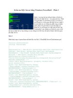
A good example of this kind of problem with motion can be found in one of the sample assemblies
that installed with SolidWorks 2007. I have included this example on the CD-ROM for your con-
venience, and it is shown in Figure 13.8. The filename for the assembly is Plunger.sldasm.
FIGURE 13.8
An assembly displaying best bet for motion
If you drag the assembly parts from the locations shown in Figure 13.8, the performance varies.
This is because when you drag the handle parts, for every position of the handle, there is only one
solution for the rest of the parts. However, when dragging the plunger bar, for every position of the
plunger bar there are two possible positions for both the links and the handle. This kind of ambi-
guity causes problems in SolidWorks assemblies such as assemblies that have open degrees of free-
dom but will not move or move in a jerky fashion.
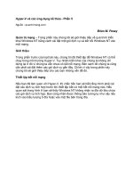
Another example of difficulties related to open degrees of freedom and motion is shown in Figure
13.9. The grippers at the end of the arm move when the rest of the arm moves, but the grippers
cannot be independently controlled. To fix this problem, you may want to either use the Fix/Float
option (available through the RMB menu), or use configurations with mates suppressed or unsup-
pressed. You can open this assembly from the CD-ROM, in the filename called Chapter 13 Robot
Assembly.sldasm.
Drag here and the motion is poor
Drag here and the motion is smooth
422
Working with Assemblies
Part III
20_080139 ch13.qxp 3/26/07 3:54 PM Page 422
FIGURE 13.9
A robot arm assembly with degree-of-freedom conflicts
Working with Advanced Mate Types
Advanced mate types greatly expand the number of ways that you can put parts together into
assemblies. Advanced mate types include the following:
n
Symmetric
n
Cam
n
Width
n
Gear
n
Rack and Pinion
n
Limit
n
Belts and Chains
423
Getting More from Mates
13
20_080139 ch13.qxp 3/26/07 3:54 PM Page 423
Symmetric mate
The Symmetric mate works a lot like the Symmetry relation in sketches, except that a plane is used
as the plane of symmetry instead of a construction line. Figure 13.10 shows a Symmetric mate
being applied to the gripper jaws. The Symmetric mate is listed in the Advanced Mates pane of the
Mate PropertyManager.
FIGURE 13.10
Applying a Symmetric mate
Cam mate
The Cam mate creates a special instance of either the Coincident or Tangent mate. Four conditions
exist with the Cam mate:
n
Coincident: Vertex on the follower mated to a cam that is created from a single closed-
loop face (spline, circle, ellipse).
n
Tangent: Cylindrical or planar face mated to a cam that is created from a single closed-
loop face.
n
CamMateCoincident: Vertex on the follower mated to a cam that is created from multi-
ple faces. This condition enables the follower to go all the way around the cam, not stop-
ping at the broken faces or following the extension of a single face.
n
CamMateTangent: Cylindrical or planar face mated to a cam that is created from multi-
ple faces. This condition enables the follower to go all the way around the cam, not stop-
ping at the broken faces or following the extension of a single face.
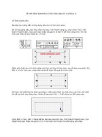
Figure 13.11 shows both single-face and multi-face cams, along with the Cam Mate interface. The
two assemblies are available from the CD-ROM in the file named Chapter 13 Cam.sldasm.
If you open the assemblies and spin the cam plate, you will notice that in both cases, the flat fol-
lower does not work very well. In fact, in the single face cam assembly, it does not work at all.
Barrel (cylindrical) cams cannot use the Cam mate to create cam motion.
NOTE
NOTE
424
Working with Assemblies
Part III
20_080139 ch13.qxp 3/26/07 3:54 PM Page 424
FIGURE 13.11
Using Cam mates
Width mate
The Width mate is often used as a replacement for the Symmetric mate in situations where parts
are modeled with some tolerance, and have a gap rather than touching face to face. The Width
mate requires two pairs of faces to be selected, and works particularly well when a part has to be
spaced evenly between two faces and there is no mid-plane, for instance when a square key is
placed in a square keyway which is somewhat larger than the key. If a mid-plane is available, the
Symmetric mate may be a better option, or at least a faster one to mate since the Symmetric mate
only requires two faces and a plane. Figure 13.12 shows a good application for a Width mate as
well as the PropertyManager interface for the mate.
FIGURE 13.12
Applying a Width mate
425
Getting More from Mates
13
20_080139 ch13.qxp 3/26/07 3:54 PM Page 425
Gear mate
The Gear mate enables you to establish gear type relations between parts without making the parts
physically mesh. You can also apply gear ratios and directions without physical connections, so
that you can have a shaft in and a shaft out of a black-box transmission. You can open the assem-
bly shown in Figure 13.13 from the CD-ROM. It is named Chapter 13 Gear Mate.sldasm. To see
the effect of the mate, open the assembly and rotate the parts. Then edit the mate and change the
ratio and direction. The selection for the Gear mate is just two cylindrical faces.
FIGURE 13.13
Applying a Gear mate
Rack and Pinion mate
The Rack and Pinion mate takes rotational motion of one part and turns it into translational
motion for a second part. Again, the parts do not need to be physically connected and can be sim-
ple representations of the actual geometry that is needed to drive the motion in the real world.
Figure 13.14 shows an assembly that uses the Rack and Pinion mate. You can find this assembly on
the CD-ROM with the filename Chapter 13 RackPinionMate.sldasm.
Limit mates
You can apply limits to distance and angle mates in order to allow the parts to move within a cer-
tain range of values. Figure 13.15 shows the PropertyManager interface for the Limit Angle mate.
Limit mates accept zero and negative values that are not normally accepted for dimensions in
SolidWorks. When used properly, Limit mates can be an extremely powerful tool for creating more
realistic motion in assemblies.
426
Working with Assemblies
Part III
20_080139 ch13.qxp 3/26/07 3:54 PM Page 426
FIGURE 13.14
Applying a Rack and Pinion mate
FIGURE 13.15
The Limit Angle PropertyManager
427
Getting More from Mates
13
20_080139 ch13.qxp 3/26/07 3:54 PM Page 427
Belt/Chain
The Belt/Chain assembly feature is not technically a standalone mate type, but it uses mates to
accomplish its task. The Belt/Chain feature can be used in two ways, to create relationships
between sketch blocks or to create relations between parts. This feature also creates a sketch and a
solid part representing the belt or chain.
Chapter 4 has a tutorial that discusses the Belt/Chain functionality as it relates to sketch blocks.
The functionality using solid parts as pulleys and sprockets is very similar.
Editing and Troubleshooting
You should become proficient with editing and troubleshooting assembly mates. If you are not com-
fortable with repairing and modifying mates, then you may find assemblies frustrating to work with; as
a result, you may avoid making changes to your assemblies. However, once you master the techniques,
you will be less afraid of errors, and more confident and willing to experiment with assembly changes.
Editing existing mates
If you are editing just one mate, then you can simply RMB click it and select Edit Feature.
Remember that you can find mates in places other than the Mates folder at the bottom of the
assembly FeatureManager; most notably, you can find them in folders under the parts that they are
mating together.
You can make several types of changes to mates, including changing the selections involved, the mate
types being used, and the mate alignment. These types of changes are all shown in Figure 13.16,
which displays a mate being edited. The selected faces are highlighted in the graphics window.
To edit multiple mates consecutively without exiting the Mate PropertyManager, it is best if you
pre-select the mates. Pre-selected mates are shown in the Mates panel as shown in Figure 13.16.
You can switch from editing one mate to another by simply selecting the new mate in the Mates
panel. If you select only one mate before clicking Edit Feature, but realize later that you want to
edit multiple mates, more mates can be selected through the Flyout FeatureManager.
After the Mates pane has been opened, you can add mates to it by selecting the mates from the
Flyout FeatureManager. This technique is somewhat problematic because after selecting a single
mate from the flyout menu, it collapses and you have to expand it again.
Here is another good place to promote the use of the Enhancement Request forms on the
SolidWorks Web site. Editing mates is a function that you will perform frequently, and so it
requires a smooth and easy-to-use interface. However, the FeatureManager and the PropertyManager
create an awkward workflow when you need to select features from the FeatureManager. An example is
when you edit the sketch plane for a sketch; as soon as you select this option, the FeatureManager dis-
appears. This can be frustrating when you just want to select a plane from the FeatureManager that was
right next to the sketch, but now you have to manually expand the flyout menu and scroll to find the
plane again. I encourage you to suggest improvements to this system directly to SolidWorks through the
Enhancement Request forms on the Support Web site.
NOTE
NOTE
428
Working with Assemblies
Part III
20_080139 ch13.qxp 3/26/07 3:54 PM Page 428
FIGURE 13.16
Editing a mate
When mate entities are lost, the mate displays a yellow triangle containing an exclamation mark,
the text changes to a brown color, and a break appears in the mate icon, as shown in Figure 13.17.
You can repair this problem by selecting the Invalid reference in the Mate Selections window and
then selecting the correct item from the graphics window.
FIGURE 13.17
Repairing mates with missing references
429
Getting More from Mates
13
20_080139 ch13.qxp 3/26/07 3:54 PM Page 429
Troubleshooting
It is best to troubleshoot an assembly mate problem as soon as it appears, and not after it has time
to become complicated by other issues. Failed mates also cause performance problems because
SolidWorks keeps trying to solve the mates that are in conflict with one another.
Assembly problems often appear to be far larger than they actually are. For example, the entire tree
may light up with warnings and error symbols when one extra or mistaken mate is applied. You
can use several approaches to troubleshoot situations like this. In fact, I sometimes purposefully
over-define mates just to locate a left-over mate or a mate that is not supposed to be there.
Two types of symbols may help you to distinguish the kinds of errors that are present in different
mate features. The yellow triangle that contains an exclamation point is really not an
error; it is
actually more of a
warning. It tells you that this mate is in conflict with other mates (this symbol is
used for a variety of warnings), but that the mate is still satisfied. One of the other mates with
which it conflicts is probably not valid, and so this type of warning is usually accompanied by an
actual error symbol where the mate is not satisfied.
The red circle containing the X is a failed mate. This is a mate that is in conflict
and is invalid. If it
is also a Coincident mate, then the two Coincident entities are not coincident.
Distinguishing between the Warnings and the
Errors
You can use the following troubleshooting techniques:
n
Last in first out: When a mate is added that causes warning and error signs to appear
throughout the design tree, you can usually correct the problem by removing this last
mate.
n
Single elimination: If you are sure that the last mate added is correct, then you may
want to go backwards up the tree starting at the bottom, suppressing individual mates
until you find one that causes the warning and error signs to disappear from the tree.
n
Single addition: It may be easier to take the opposite approach, by suppressing all but
the mates that you are sure of, and then gradually unsuppressing mates until the conflict
reappears.
n
Suppress a part: With all of the mates active, try suppressing an individual part to see if
this makes a difference. If it does, then unsuppress the part and look at the mates for that
part in the Mates folder under the part.
n
Mate Xpert: The Mate Xpert is an automated routine that creates subsets of groups of
conflicting mates. Each subset of mates has one mate that is not satisfied because of the
conflict. This may help you to find the cause of the conflict. Figure 13.18 shows the Mate
Xpert interface. You can access the Mate Xpert from the RMB menu.
430
Working with Assemblies
Part III
20_080139 ch13.qxp 3/26/07 3:54 PM Page 430
FIGURE 13.18
The Mate Xpert interface
In the past several releases, SolidWorks has become increasingly “error-phobic.” There
are more and more ways to create mate errors that are simply not reported to the user.
For example, if geometry goes missing from a part, the mate icon displays with a break on it, but the
mate folder is not flagged. This means that you do not know that you have a broken mate until you go
looking for it.
Another example is that when a mated part is fixed (using the Fix option), the conflicting mates are
automatically suppressed without notifying the user. In addition, when a part is suppressed, the mate
is shown as suppressed, but it is also shown as broken. As a result, you are unsure whether the mate is
completely invalid or the parent parts are only suppressed.
CAUTION
CAUTION
431
Getting More from Mates
13
20_080139 ch13.qxp 3/26/07 3:54 PM Page 431
Examining Mate Options
The Options pane of the Mate PropertyManager is shown in Figure 13.19. Most of the options are
self-explanatory, except for the Use For Positioning Only option. This option positions a part but does
not apply a parametric mate. Some users make extensive use of this option for various applications
where you need the part located precisely, but do not need or want a mate. Positioning parts for
Animator animations where the part does not move according to a mate is one example of a use for
this option.
FIGURE 13.19
The Options pane of the Mate PropertyManager
Summarizing Mate Best Practices
Sometimes best practice recommendations can contradict one another, and for each best practice
recommendation that you find, there are likely several specific situations where the recommenda-
tion is invalid. As a result, you should apply the following recommendations carefully.
n
Each assembly should have at least one part that is either fixed or fully mated to the stan-
dard planes of the assembly so that it cannot move relative to the assembly.
n
You should use fixed parts sparingly. One part that serves as a “ground” for the assembly
should be fixed. Other than that, the parts of imported assemblies are sometimes fixed to
keep them from being moved accidentally.
n
Do not mate to time-dependent features in the assembly tree, or to in-context features in
parts. You may want to refer to Chapter 12 for a refresher on time-dependent features in
the assembly tree. This can create circular references where the assembly must be rebuilt
multiple times to fully resolve the positions of all parts and sketches.
n
When possible, it is best to mate all parts to the “ground” part. Creating daisy-chain mates
(where A mates to B which mates to C, and so on) forces the mates to be solved in a partic-
ular order, which may take more time to solve than otherwise. If all of the mates relate to
established assembly references, the mates may be more stable. Chapter 11 describes using
a skeleton in a part to make sketch and feature relations to. The concepts are similar.
432
Working with Assemblies
Part III
20_080139 ch13.qxp 3/26/07 3:54 PM Page 432
n
When possible, leave part positions fully defined, especially when other geometry is
dependent upon the position of parts. Some examples include in-context features, assem-
bly features, or assembly-level reference geometry, which are dependent on part geometry.
n
Constraining the rotational degree of freedom for components such as screws, washers,
and nuts is usually considered excessive. At times, open degrees of freedom may cause
problems with complex motion, such as a gripper on the end of a robotic arm.
SolidWorks functions well when there is a single, well-defined path between two points,
but when there are multiple options, the software may become confused.
n
Do not leave errors unresolved in the tree.
n
Remember to use subassemblies to break up the number of mates that are solved in the
top-level assembly.
n
Limit the use of flexible subassemblies.
n
Do not mate to entities that may be removed later by suppressing or unsuppressing fea-
tures, especially edges or faces that are created by features such as fillets. For this reason,
it is usually best to wait until parts are complete before you use them to create an assem-
bly, although this is rarely practical.
n
Use a degree-of-freedom analysis to prevent mates from becoming over-defined.
Tutorial: Mating for Success
In this tutorial, you will put together a model of a robotic arm to better understand some of the
mate issues discussed in this chapter. Follow these steps to mate for success:
1. Open the part named Chapter 13 Robot Base.sldprt from the CD-ROM.
2. In the part document window, click the Make Assembly From Part icon, and click the
cursor on the Origin of the assembly to place the part Origin at the assembly Origin. The
part is automatically fixed in place.
3. Click Insert ➪ Component ➪ Existing Part/Assembly. Click the Browse button in the
PropertyManager, and find the part called Chapter 13 Robot Tower.sldprt. This part con-
tains a Mate reference to help you mount it to the base. If you bring the cursor near the
big circular hole in the base, you can see the transparent preview of the tower snap into
place. Click to accept this placement. Figure 13.20 shows this placement in progress.
Notice that the cursor appears as a SmartMate cursor for the peg-in-hole mate. When the
part is dropped, check the mate list to confirm that a Concentric and a Coincident mate
have been applied by the Mate reference.
433
Getting More from Mates
13
20_080139 ch13.qxp 3/26/07 3:54 PM Page 433
FIGURE 13.20
A Mate reference being used to SmartMate a component
4. Open the part with the filename Chapter 13 Arm.sldprt in its own window, and click
Window
➪ Tile Vertically. The part and the assembly should be open in adjacent windows.
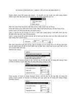
5. Click the face inside the hole without the chamfer around it in the Arm part, as shown in
Figure 13.21. Then drag it into the assembly to the cylindrical face inside the hole at the
top of the Robot Tower part. The concentric SmartMate symbol should appear on the
cursor.
6. Click the green check mark icon to accept the Concentric mate. Move the part to test that
the mates are correct.
7. Click the Mate tool on the Assemblies toolbar. Expand the Advanced Mates panel and
click the Width mate.
8. In the Width Selections box, select the two inner faces of the Robot Tower part, and in
the Tab selections box, select the outer faces of the Arm part. The selection should look as
shown in Figure 13.22.
434
Working with Assemblies
Part III
20_080139 ch13.qxp 3/26/07 3:54 PM Page 434
FIGURE 13.21
Displaying a SmartMate when dragging between windows
9. Open a Windows Explorer window, and select the following parts: Chapter 13 Robot
Arm2 and Chapter 13 Robot Gripper. Drag these parts into the SolidWorks assembly
window, and drop them in a blank space.
10. Select the chamfered faces of the Arm and Arm2 parts and create a Coincident mate
between them. You can make Coincident mates between conical faces as long as the
cones are the same angle. This special case acts like a combination of Concentric and
Coincident mates. Figure 13.23 shows the selections and the results.
Drag the inner face of the hole
435
Getting More from Mates
13
20_080139 ch13.qxp 3/26/07 3:54 PM Page 435
FIGURE 13.22
Creating a Width mate
FIGURE 13.23
Making conical faces coincident
Select these faces
436
Working with Assemblies
Part III
20_080139 ch13.qxp 3/26/07 3:54 PM Page 436
11. Create a copy of the gripper part so that there are two instances of it in the assembly. You
can do this by Ctrl-dragging the part within the assembly window.
12. Mate both of the grippers to the Arm2 end using the same mating technique that you
used for the previous conical face Coincident part.
13. Once you have applied these parts, try moving the various joints of the assembly. Notice
that it is difficult, if not impossible, to isolate the motion of just a single part. This is
because there are too many open degrees of freedom, and a lot of ambiguity.
14. Fix Arm2 to allow you to move the gripper parts as you want. Create a Symmetric mate
between the indicated faces of the grippers and the Front plane of the Arm2 part, as
shown in Figure 13.24.
FIGURE 13.24
Creating a Symmetric mate
15. Practice making angle mates, suppressing mates, and fixing parts to limit motion.
16. Save the assembly and exit the file.
Faces for symmetric mate
437
Getting More from Mates
13
20_080139 ch13.qxp 3/26/07 3:54 PM Page 437
Summary
A thorough understanding of mates, and editing and troubleshooting techniques in particular,
makes the difference between a real assembly artist and a user who struggles through or avoids cer-
tain tasks. There is a lot about mates that is not simply straightforward, but with practice, you can
understand and master them. You can put assemblies together quickly, with a focus on rebuild per-
formance and Dynamic Assembly Motion.
Although best practice concepts should not dominate your designs, they are great guidelines to
start from. Watch out for the pitfalls outlined in the Summary of Mate Best Practices section in this
chapter to avoid making big mistakes.
438
Working with Assemblies
Part III
20_080139 ch13.qxp 3/26/07 3:54 PM Page 438
A
ssembly configurations enable you to control many things, including
part configurations, suppression, visibility, color, and assembly fea-
ture sizes. They also allow you to control assembly layout sketch
dimensions, mate values, suppression states, and several other items. What
you will learn in this chapter about assembly configurations builds on the
information in Chapter 10, which discussed part configurations. In this
chapter, design tables will also be expanded upon to show how they are used
in conjunction with SolidWorks assemblies.
The Display States function was new in SolidWorks 2006. Display States are a
better performance alternative to using configurations to control visibility of
parts in assemblies. Display State options are discussed at length in this chapter.
Using Display States
If you are using an older version of SolidWorks, then you may not have
access to Display States, which were not introduced until SolidWorks 2006.
They are a very useful addition to the software as they allow you to visualize
the assembly in various ways. One of the best things about Display States is
their ability to show parts in different display modes (Shaded, Wireframe,
HLR, Shaded with Edges) simultaneously.
Users have always been able to show parts transparent and shaded at the
same time, and a common workaround for combining Shaded and
Wireframe modes was to display the parts as Shaded with Edges, but to
make some parts completely transparent. This would give the effect of some
parts being shown in Wireframe mode. Because of Display States, this
workaround is no longer necessary.
439
IN THIS CHAPTER
Display States
Assembly configurations
Exploded views
Tutorial: Working with assembly
configurations
Assembly Configurations
and Display States
21_080139 ch14.qxp 3/26/07 3:56 PM Page 439