SolidWorks 2007 bible phần 7 pdf
Bạn đang xem bản rút gọn của tài liệu. Xem và tải ngay bản đầy đủ của tài liệu tại đây (5.31 MB, 111 trang )
Ironically, this mode does not work for the Relative view, which would be a perfect application for
it. It is intended for views such as the Broken-out Section view where a depth must be selected for
the cut.
In Figure 21.22, notice the small toolbar above the drawing view. This toolbar is available while
the 3D Drawing View Mode is turned on. Clicking OK on the small toolbar turns off the mode and
returns the view to its previous state.
FIGURE 21.22
3D Drawing View Mode
View orientation and alignment
Although you may have selected the Top view, and it displays the correct geometry, you may want
to spin the view in the plane of the paper, or orient it in a particular way. You can do this using two
methods. The easiest way to reorient the view is to use the Rotate View tool on the View toolbar.
This rotates the view in the plane of the paper much like it rotates the model in 3D.
Another option is to select an edge in the view and assign the edge to be either a horizontal or ver-
tical edge. Figure 21.23 shows how a view can be re-oriented using this tool, which is located at
Tools
➪ Align Drawing View ➪ Horizontal or Vertical Edge.
Another option for view alignment is to align it relative to another view; this involves stacking one
view on top of another or placing them side-by-side. You can do this by selecting the second pair
of options in the menu shown in Figure 21.23, Horizontal to Another View and Vertical to Another
View.
Situations may arise where a view is locked into a particular relationship to another view, and you
need to disassociate the views. The Break Alignment option, which is grayed out in the menu in
Figure 21.23, serves that purpose.
Default Alignment resets a view to its original orientation and alignment if it has been altered.
637
Working with Drawing Views
21
30_080139 ch21.qxp 3/26/07 4:13 PM Page 637
FIGURE 21.23
Rotating a drawing view to align an edge
Using Display Options in Views
Some important display options and settings are not listed in Tools, Options, but are only available
through the menus. You can find more information about the display options and settings that are
available through Tools, Options in Appendix B.
Display States
Display States can be used in drawing views, but they only have an effect when a drawing view is
set to Shaded Display mode. You can control Display States for drawing views in the View
Properties tab of the Drawing View Properties dialog box. RMB click inside the view but away from
any geometry, and select Properties. The Drawing View Properties dialog box appears, as shown in
Figure 21.24.
One of the limitations of the Display States functionality in drawing views is that when wireframe
display is used, the drawing edges appear black rather than using the color settings to show wire-
frame in the same color as shaded.
Selected edge
638
Creating Drawings
Part V
30_080139 ch21.qxp 3/26/07 4:13 PM Page 638
FIGURE 21.24
The Drawing View Properties dialog box
Display modes
With even the 2D drawing world becoming less and less black-and-white, SolidWorks drawings
have the ability to apply shaded views to drawings. This is probably most useful in isometric, per-
spective, or pictorial views on the drawings. The shading and color may be distracting for dimen-
sioned and detailed views, but it can also be indispensable when you need to show what a part
actually looks like in 3D. Not everyone can read engineering prints, and even for those who can,
nothing communicates quite like a couple of shaded isometric views.
The more standard 2D drawing display modes are Wireframe, HLR (hidden lines removed), and
HLV (hidden lines visible), which work in the same way as they do in the model environment.
Unless you override it, the Display mode is set for all of the components in the view.
Component Line Font
Individual components within an assembly can be shown in different fonts, similar to the display
in the Alternate Position view. You can access this function through the component RMB menu, by
selecting Component Line Font. Figure 21.25 shows the Component Line Font dialog box, along
with a drawing view in which a couple of part line fonts have been changed. The part can only be
changed in the view where it was selected, or it can be changed across the board in all views in the
active drawing where it appears. This is useful if you want to emphasize or de-emphasize certain
parts in the assembly view.
639
Working with Drawing Views
21
30_080139 ch21.qxp 3/26/07 4:13 PM Page 639
FIGURE 21.25
The Component Line Font dialog box
Layers
Yes, SolidWorks drawings can use layers. No one likes to admit this, but it is nonetheless true. You
can place individual parts onto layers, and the layers can have different colors and fonts. Most enti-
ties can be put into layers, including edges, annotations, and sketch items. Hidden layers are often
used for reference information or construction entities on a drawing.
Edge display options
SolidWorks drawings and models offer some options for displaying tangent edges. Many users find it
distracting when tangent edges (which in a physical part are not edges at all) are given as much visi-
ble weight as the sharp edges of, say, a chamfer. These settings are found at View
➪ Display, as shown
in Figure 21.26. The Tangent Edges Removed option may be appropriate for parts with few fillets,
but it causes a part to look over-simplified and makes details of the shape difficult to distinguish.
FIGURE 21.26
Edge display options
Tangent edges visible
Tangent edges with font
Tangent edges removed
640
Creating Drawings
Part V
30_080139 ch21.qxp 3/26/07 4:13 PM Page 640
View quality settings
View quality is one of those issues that keep users confused because it has changed so many times
in recent releases. If you look for view quality settings, then you may be looking for some time. Are
the settings with the view, the sheet, system options, document properties? Where are they?
You have the choice between two options for drawing view quality: high quality and draft quality.
The quality that you choose influences the performance of the software. Draft quality views are
noticeably rough when viewed closely, but from a distance, they are at least recognizable. However,
Draft quality is becoming less accessible, and so I would not recommend relying on this option.
Although new Draft Quality views can be created, once they are set to High Quality, they cannot be
set back to Draft Quality.
In SolidWorks 2007, all views are created as High Quality unless the view quality setting is over-
ridden. This setting is found at Tools
➪ Options ➪ System Options ➪ Drawings ➪ Display
Style
➪ Display Quality For New Views. The only other way that you can create Draft Quality
views in this version is if you open a drawing from an older version of SolidWorks that used
draft quality views.
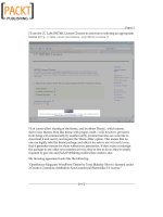
In Figure 21.2 earlier in the chapter, the image to the right shows the Display Style pane. This
PropertyManager has been taken from a High Quality view. A Draft Quality view enables you to
toggle between Draft and High quality, as shown in Figure 21.27. This means that you can switch a
view from Draft to High, but not from High to Draft. Also notice in Figure 21.27 that the cursor
over a Draft Quality view displays a lightning bolt symbol, indicating draft quality.
FIGURE 21.27
The Draft Quality options and cursor
You can access the Cosmetic Thread Display setting in both the Step 1 PropertyManager and the Step
2 PropertyManager. However, you need to be careful not to misread the interface, by thinking that
either of these interfaces controls the View Quality. The best advice for using the view quality settings
is to forget about them. It looks like this function is being phased out or at least discouraged.
641
Working with Drawing Views
21
30_080139 ch21.qxp 3/26/07 4:13 PM Page 641
Distinguishing Views from Sheets
It is sometimes difficult for new users to understand the difference between being in a sketch and
being
out of a sketch, or the difference between editing the sheet as opposed to the sheet format. In
the same way, confusion frequently surrounds the difference between sketching in a view and
sketching on a sheet. The easiest way to determine if a sketch will be associated with a view or with
the drawing sheet is to look at the prompt in the lower-right corner of the SolidWorks window, on
the status bar, which displays the message, Editing Sheet, Editing Sheet Format, or Editing View.
This issue becomes especially important when you want to do something with a sketch entity, but
it is grayed out and unavailable. This means that whatever entity is active is
not the one that the
sketch entity is on. Drawing views expand to contain all of the sketch entities that are associated
with the view, and so if you see a view that is extended on one side, larger than it should be, then it
could be extended to contain the grayed-out sketch entity. Activate the sheet and the suspected
views; when the sketch entity turns from gray to black, you have found the place where it resides.
Tutorial: Working with View Types,
Settings, and Options
This tutorial is intended to familiarize you with many of the view types, settings, and options that
are involved in creating views. To begin, follow these steps:
1. From the CD-ROM, open the part called Chapter 21 – Tutorial Part.sldprt.
2. Move the drawing template named Inch B Bible Template.drwdot, also found on the
CD-ROM, to your templates folder. If you do not know where your templates are located,
go to Tools
➪ Options ➪ System Options ➪ File Locations ➪ Document Templates.
3. From the window with the open part, click the Make Drawing from Part button from the
toolbar. The drawing becomes populated with three standard views and an isometric
view, as shown in Figure 21.28.
4. In the drawing document, turn on the display of the Origins. This will help you to align a
section view. Origins can be displayed through the menus at View
➪ Origin.
5. Click the Section View tool on the Drawings toolbar. This activates the Line sketch tool.
642
Creating Drawings
Part V
30_080139 ch21.qxp 3/26/07 4:13 PM Page 642
FIGURE 21.28
Using a template with Predefined views
6. In the Top view (in the upper-left section of the drawing), draw a line that picks up the
inference from the Origin. You may have to run the cursor over the Origin to activate the
inference lines. Make sure that the line goes all the way through the model geometry in
the view, as shown in Figure 21.29. When you finish the line, the section view is ready to
be placed. Place it to the right of the parent view.
FIGURE 21.29
Creating a section view
643
Working with Drawing Views
21
30_080139 ch21.qxp 3/26/07 4:13 PM Page 643
When sketching, remember to make sure that you are sketching in the view rather than
on the sheet. A section view cannot be created from a sketch entity if it is not in a view. A
glance at the status bar in the lower-right corner of the window lets you know if you are
in Editing View or Editing Sheet.
To change the letter label on the drawing, click the section line and change the label in
the top panel of the Section View PropertyManager.
7. Bring the cursor over the sharp bend in the section line until the cursor looks like the
image to the left. Double-click the cursor; the section arrows flip to the other direction,
and the drawing view becomes cross-hatched. The cross-hatching indicates that the view
needs to be updated.
8. Press Ctrl+Q; the view updates, removing the cross-hatching.
9. Click the section line and press Delete. Answer Yes to the prompt. If you are familiar with
older versions of SolidWorks, then you may notice that the original sketch is also deleted
with the section line and the view, so that you do not have to delete separate elements
individually.
10. Create a new section view using a jogged section line, as shown in Figure 21.30. In order
to do this, you must pre-draw the jogged section line, and press the Section View button
with the part of the line that you want to use to project the new view.
FIGURE 21.30
Creating a jogged section view
11. Next, click the Detail View button on the Drawings toolbar. This activates the Circle
sketch tool.
12. Sketch a circle in the Front view, located in the lower-left section of the drawing. Try not
to pick up any automatic relations to the center of the circle. One way to prevent this is
to hold down the Ctrl key when creating the sketch.
13. Place the view when the circle is complete. Note that the view was created at a scale of
1:2. The sheet scale is 1:4, and so the detail is two times the sheet scale. The Detail view
is shown in Figure 21.31.
644
Creating Drawings
Part V
30_080139 ch21.qxp 3/26/07 4:13 PM Page 644
FIGURE 21.31
Creating a Detail view
14. Drag the circumference of the circle and watch the view dynamically resize.
15. Leave the Detail circle selected so that the center of the circle is highlighted. Drag the cen-
ter of the circle around the view. The effect is like moving a magnifying glass over the
part. If you drag the center with the Ctrl key pressed, then you will not pick up any auto-
matic sketch relations when you drop it somewhere.
16. Click the Broken-out Section View tool on the Drawings toolbar. Draw a spline similar to
the one shown in the image to the left in Figure 21.32. Splines take a little practice.
FIGURE 21.32
Creating a Broken-out Section view
17. Click inside the view border but outside of the part in the Top view (in the upper-left sec-
tion of the drawing). Press Ctrl+C.
18. RMB click the tab in the lower-left corner of the drawing that says Sheet1, and select Add
New Sheet. If you used the template that I provided, a message may appear, saying that
SolidWorks cannot find the format. This is because I only supplied you with the template
file, not the format as a separate file. In any case, switch to the B size format and accept.
645
Working with Drawing Views
21
30_080139 ch21.qxp 3/26/07 4:13 PM Page 645
19. Click any spot inside the sheet and press Ctrl+V. SolidWorks pastes the copied view from
the other sheet. Delete the section line.
20. Click the Projected View tool from the Drawings toolbar, and then click the pasted view.
Practice making a couple of projected views, including dragging one off at a 45-degree
angle to make an isometric. Make sure that one of the views is a side view showing the
angled edge, as shown in Figure 21.33. Once you create the views, click model edges in
the views and drag them around to a better location.
FIGURE 21.33
Projecting views
21. Select the angled edge from one of the side views and click the Auxiliary View toolbar
button. While placing the view, press and hold the Ctrl key to break the alignment. You
can resize the view arrow by selecting the corners and dragging. If you drag the line itself,
then you can move it between the views. Alternatively, with the view arrow selected and
the PropertyManager displayed, you can deselect the green check mark icon in the Arrow
panel at the top of the window to turn off the arrow.
22. Create a new drawing from the New dialog box. If the automatic Model View interface
appears in the PropertyManager, click the red X icon to cancel out of it.
23. Expand the Task pane and activate the View palette (the tab that looks like a drawing
icon). Click the ellipse button (. . .) and browse for the assembly named Chapter 21. SF
casting assembly.sldasm. This is shown in Figure 21.34.
Create at least one of these views
646
Creating Drawings
Part V
30_080139 ch21.qxp 3/26/07 4:14 PM Page 646
FIGURE 21.34
The View palette
24. Drag the Back view onto the drawing. Notice that when you use this technique, the views
do not resize automatically, regardless of the setting at Tools
➪ Options ➪ Drawings ➪
Automatically Scale New Drawing Views.
25. Delete any view that you have created using this method. Open Windows Explorer,
browse to the assembly, and drag it into the drawing. The views that you create using this
method are equivalent to the Standard 3 View tool. This time, the views auto-size.
26. Select the Front view and change it to the Back view. Notice that the rest of the views
change to reflect the new parent view.
27. Zoom in on the Back view. Change the view to show Tangent Edges With Font through
View
➪ Display.
28. Click the Alternate Position view toolbar button. Type a name in the PropertyManager for
a new configuration and click the green check mark icon. SolidWorks opens the assembly
model window.
29. Rotate the handle 90 degrees and click the green check mark icon. SolidWorks returns to
the drawing and shows the new position in a dashed font, as shown in Figure 21.35.
30. Place an isometric view on the drawing. Change the Display Mode to make it a shaded
view.
647
Working with Drawing Views
21
30_080139 ch21.qxp 3/26/07 4:14 PM Page 647
FIGURE 21.35
Creating an Alternate Position view
31. RMB click inside the view but away from the parts, and select Properties. The dialog box
appears, as shown in Figure 21.36. Make sure that the view is set to use the Default con-
figuration, and also select the Show in Exploded State option.
FIGURE 21.36
The Drawing View Properties dialog box
648
Creating Drawings
Part V
30_080139 ch21.qxp 3/26/07 4:14 PM Page 648
Summary
SolidWorks has the capacity to make many different types of views of parts and assemblies. In
addition to the tools for projecting views, custom views saved in the model document can be saved
and used on the drawing. The associative nature of the drawing to the model helps ensure that
drawing views, regardless of how unusual the section angle or view orientation, are displayed in
the correct size, location, and geometry.
It is sometimes better to create some of the views that require sketches by pre-sketching. Make use
of workflow enhancements when possible; for example, the Broken-out Section automated work-
flow works well, but forcing it to be a manual process makes it awkward to use.
649
Working with Drawing Views
21
30_080139 ch21.qxp 3/26/07 4:14 PM Page 649
30_080139 ch21.qxp 3/26/07 4:14 PM Page 650
A
nnotations and symbols are a major component of communicating a
design through a drawing. SolidWorks has several options available
to help you manage these entities to make engineering drawings look
good and communicate effectively.
Using Notes
Notes are the workhorse of SolidWorks annotations. You can use notes in
many different configurations, and mix them with links to custom proper-
ties, hyperlinks, and text wrapping boxes. You can also use them with
favorites, leaders, balloons, and symbols.
The workflow for placing notes
Sometimes users have difficulty working through some of the interfaces in
SolidWorks. This is not necessarily the fault of the software, but is often
because users may not fully understand how the workflow of a particular
feature is supposed to function. The Model View interface from the last
chapter is one that can be confusing until you have been through it a few
times and gain a more intuitive feel for how it works.
Understanding the workflow is paramount to being able to use the software
efficiently. I sometimes find myself using the Annotations clumsily, and
sometimes wind up with blank notes, double notes, or extra lines at the ends
of notes. After using the tool a few times, I get back in the groove.
For these reasons, I have added some step-by-step suggestions here to help
you establish expectations that will enable you to use a fast workflow with
annotations.
651
IN THIS CHAPTER
Using notes
Using blocks
Using symbols
Using center marks and
centerlines
Tutorial: Using annotations
Using Annotations
and Symbols
31_080139 ch22.qxp 3/26/07 4:14 PM Page 651
Follow these steps to create a note:
1. Click the Note toolbar button on the Annotations toolbar.
2. Click in the graphics window where you want to create the note or click an entity that
you want the note leader to point to, and
then click where you want the note.
3. Type the note. Press Enter at the end of a line, or, if you intend to force the note to wrap,
just allow the line of text to be as long as it wants to be. While you create the note, the
text box expands to the right until you press Enter, and it expands down every time a line
is added.
At the end of the last line of the note,
do not press Enter again (this creates extra lines)
and
do not press Esc (this causes the entire note to disappear).
4. To finish the note, click the mouse outside of the text box. After that, if you are done,
press Esc. If you want to continue with another note, click again to place it, and start typ-
ing. If you want to place the same note as the first one again, the text is already there, so
click a second time.
Fonts
SolidWorks uses any TrueType fonts that Windows will accept. This includes symbol, non-English,
and Wingding fonts. SolidWorks does not use true monofonts like AutoCAD, because they do not
have width information. Some look-alike fonts are installed with SolidWorks that do have a very
narrow width, and are shaped like some of the monofonts.
If you are a long-time SolidWorks user, you will be pleased to know that in recent versions of the
software, different pieces of text within a single note can be formatted with multiple fonts, multiple
sizes, bold, italics, underline, and so on.
The Fonts toolbar displays with two different names. If you use it in the CommandManager, it displays
with the Fonts name, with the icon shown at the beginning of this Fonts section. In Tools, Customize,
the Fonts toolbar displays as the Formatting toolbar. The Formatting toolbar also appears in the graph-
ics area immediately over your text every time you either insert a new note or edit an existing note,
unless the toolbar is already docked somewhere. The Formatting toolbar is shown in Figure 22.1.
FIGURE 22.1
The Formatting toolbar
Text boxes and wrapping
Text boxes are a more recent addition that enables the user to limit the size, particularly the width,
that a note can occupy. This enables notes to wrap in tight spaces on title or revision blocks, as well
as other places.
652
Creating Drawings
Part V
31_080139 ch22.qxp 3/26/07 4:14 PM Page 652
You can size text boxes immediately after placement, even while they are blank; the text then
wraps as you type it. The text box expands downward automatically. Blank text boxes can be left
on the drawing to provide a placeholder for future text. The blank text box has a rectangular bor-
der that contains an X, both of which are removed when you add text. If spaces are added to a text
box, the text box becomes invisible, although you can select it if you know where it is. When you
move the cursor over the text box, the cursor displays the note symbol. Text boxes do not high-
light when window selected.
While typing a note, it is not possible to resize the note using the middle handle on the right end
of the box; you should use the lower-right corner handle, as shown in Figure 22.2.
FIGURE 22.2
Resizing a text box using the lower-right corner handle
If a custom property is used to populate a note, and the value of the property is long, you may
have difficulty getting the text of the property to wrap. One way to accomplish this is to make the
font of the note very small, then size the box to the appropriate size, then set the note font back to
the original size. The text now wraps to fit the box.
Notes and leaders
When you start to place a note, a preview shows the text box with or without a leader depending on
the position of the cursor. If the cursor is over a blank section of the drawing, the note is placed with-
out any leader. If the cursor is over a face, edge, or vertex, then a leader is added using the arrow con-
trolled by the settings at Tools
➪ Options ➪ Document Properties ➪ Arrows ➪ Attachments. By
default, a leader attached to a face uses a dot as an arrow, and a leader attached to an edge, sketch
entity, or nothing at all uses a regular arrow. You can change these defaults at the options location
mentioned above, and you can change individual note leaders in the PropertyManager that becomes
available when you select a note.
Figure 22.3 shows the preview that is displayed by the cursor when you place a note over a face,
over an edge, and over blank space on the drawing.
You can also change settings for bent leaders in the Tools
➪ Options ➪ Document Properties area.
It is recommended that you use the same bent leader lengths for all annotations, and save them in
the templates that you use.
Use corner handle to resize
Do not resize box with middle handle
653
Using Annotations and Symbols
22
31_080139 ch22.qxp 3/26/07 4:14 PM Page 653
FIGURE 22.3
Placing a note with a leader
Some minor but basic functionality appears to be missing from notes in SolidWorks. Single-clicking
inside an active text box places the cursor between letters, as expected. Double-clicking inside an
active text box selects the entire word that you click, again as expected. Triple-clicking in Microsoft
applications such as Word and PowerPoint generally selects the whole paragraph or the contents of the
text box. However, the triple-click option is not available in SolidWorks notes. Ctrl+A does work to
select all of the text inside a text box. To format the entire note, do not activate the text box; instead,
only select the note, and apply the setting to the entire note rather than to selected text within the note.
You also cannot drag-and-drop selected text to move it within a text box. However, you can
Ctrl+C, Ctrl+X, and Ctrl+V the text.
Adding a leader to a note
To add a leader to a note that was created without a leader, click the note and select the leader
options in the Leader panel of the PropertyManager, as shown in Figure 22.4. After you add the
leader, you can reposition the handle at the end of the leader to attach it to an entity on the drawing.
FIGURE 22.4
Adding a leader to a note
654
Creating Drawings
Part V
31_080139 ch22.qxp 3/26/07 4:14 PM Page 654
Multiple leaders
You can also attach multiple leaders to notes. To create a new note with multiple leaders, preselect
the entities that the leaders are to be attached to, and then click the Note toolbar button.
To add a leader to an existing note, first click the note, and then Ctrl-drag the handle on the end of
the leader to the second location. A note with multiple leaders is shown in Figure 22.5. To remove
one of multiple leaders from a note, click the handle at the end of the arrow and press Delete.
FIGURE 22.5
A note with multiple leaders
Jogged leaders
Jogged leaders have come a long way since their introduction many releases ago. You can switch a
regular leader to a jogged leader by selecting an option in the PropertyManager. In Figure 22.4, the
middle icon in the top row is the Jogged Leader icon. The icon to the left simply turns on the
default leader, and the icon to the right turns off leaders altogether.
Once you activate the jogged leader option, you can add a jog from the leader RMB menu. Notice
in Figure 22.6 that two options give you control over the jogged leader.
FIGURE 22.6
Jogging a leader
655
Using Annotations and Symbols
22
31_080139 ch22.qxp 3/26/07 4:14 PM Page 655
Add Jog Point
Selecting the Add Jog Point command adds a new handle to the leader that you can move around.
You can add multiple jog points to the leader.
Insert New Branch
The Insert New Branch command enables you to create a new jogged leader that ends in another
arrow from the selected point. This arrangement with multiple branches in a jogged leader is
shown in Figure 22.7.
FIGURE 22.7
The results of adding a new branch to a jogged leader
Favorites
For notes, a favorite can apply a font, an underline or bold formatting, or any other setting from
the Formatting (Fonts) toolbar.
To create a note that uses the favorite setting from another existing note, pre-select the existing
note before starting the Note command; SolidWorks applies the favorite to the new note.
Sometimes adding a favorite to a note can make other changes that you may not expect,
such as turning off the leaders if a note has multiple leaders. In particular, if the favorite
is made from a note with a jogged leader, then it turns off leaders for regular multiple leaders.
Favorites that are created from regular leader notes do not turn off jogged leaders.
Making a change to the leader of a note after you apply the favorite removes the favorite from the
note, although the formatting remains. This does not apply to adding multiple leaders, only to chang-
ing the type of leader.
Applying a favorite may also remove the ability of the text to wrap, as well as any changes to the text
box shape. You cannot move the corner of a text box of a note to which you have applied a favorite.
Favorites exist only in the document in which they were created, but they can be shared to other
documents by saving the favorite out as a separate file. Note favorites use the extension, *.sldnote-
fvt. Once you save the favorite, you can load it into other documents. The Favorites panel of the
Note PropertyManager interface is shown in Figure 22.8.
CAUTION
CAUTION
656
Creating Drawings
Part V
31_080139 ch22.qxp 3/26/07 4:14 PM Page 656
FIGURE 22.8
The Favorites panel of the Note PropertyManager interface
The Favorites panel contains the following buttons:
Apply Defaults/No Favorites: Removes favorite settings from the current interface,
setting all values back to the defaults.
Add or Update Favorites: This can be used to either add a new favorite to the data-
base or to change the name or other settings for an existing favorite.
Delete Favorite: Removes a favorite from the database.
Save Favorite: Saves a favorite to an external file (*.sldhwfvt), which can be loaded by
other users and added to their databases.
Load Favorite: Loads a saved favorite file.
Favorites can be loaded into document templates so that for every document created from the tem-
plate, those Favorites will be available.
Linking notes to custom properties
You can link notes to custom properties. The custom properties can be from the drawing, or from
the model that is referenced by the drawing. This kind of link is also mentioned briefly in Chapter
20, but I discuss it more thoroughly here.
Figure 22.9 shows a note on a drawing with custom property links pulling data from the model
shown on the drawing. To add these links, driven by the syntax
$PRPSHEET:”material”, click
the icon indicated in the image to the right in Figure 22.9.
In this case, text has been combined with custom properties, but custom properties can also
appear alone. The Custom Properties interface is found at Tools, Properties.
Hyperlinking text
Hyperlinking text is sometimes useful on drawings to provide a link to reference documentation,
specification, test results, and so on. The first button in the Text Format panel enables you to add a
hyperlink to text in the note. Either copy the URL to the hyperlink dialog box that appears, or
browse to it from the dialog box.
657
Using Annotations and Symbols
22
31_080139 ch22.qxp 3/26/07 4:14 PM Page 657
FIGURE 22.9
Linking notes to custom properties
Notes and symbols
Notes and symbols are regularly combined in SolidWorks. Symbols are discussed more fully later
in this chapter, but are mentioned here because of the frequency with which they are used with
notes. The image to the right in Figure 22.9 shows the Text Format panel, which contains a button
to the interface where you can add symbols.
Using Blocks
Blocks in SolidWorks can contain sketch elements and notes. When used in drawings, blocks have
several common uses, including the following:
n
Standard note blocks for tolerances, disclaimers, or default requirements
n
You can put together a mechanism in 2D where each block represents a part
n
Flow direction for fluid systems
n
Drawing stamps such as “Not For Release,” “Preliminary,” “Obsolete,” and so on
n
Symbols for schematics which can be snapped together
n
You can save drawing templates as blocks to make them easier to place as a single entity
Like favorites, blocks reside in the document in which they are created, but you can save them out
to a *.sldblk file, load them into other documents, and save them as a part of a document template.
Link to
Custom Properties
Hyperlink text Add symbol
658
Creating Drawings
Part V
31_080139 ch22.qxp 3/26/07 4:14 PM Page 658
Inserting blocks
You can apply blocks in several ways, including by dragging from Windows Explorer and by using
the menus at Insert
➪ Annotations ➪ Block. However, the most efficient way is to access them from
the Design Library. Library folders can be established specifically for blocks. Check the settings at
Tools
➪ Options ➪ File Locations ➪ Blocks, and redirect this setting to a library area outside of the
SolidWorks installation directory. Figure 22.10 shows the Design Library with a folder containing
blocks that are selected. The blocks do not show previews in the window, but the tooltip displays
large previews. You can drag blocks from the Design Library onto the drawing sheet.
FIGURE 22.10
Blocks in the Design Library
Each block has an insertion point, which snaps to any sketch entity endpoint, even if it is in
another block. This makes schematics easy to snap together. If the default insertion point is not the
point that you need to snap to the other geometry, then you can place the block anywhere on the
drawing and drag the point that needs to snap.
Once blocks are snapped together, to detach them from one another, you can click the point at
which they touch; a Coincident sketch relation displays in the PropertyManager. Deleting the
sketch relation enables you to drag the block away from the other geometry.
When blocks are inserted, you can control several options in the PropertyManager. This function
may be somewhat hidden because it does not appear automatically when you place the block.
After you place the block, SolidWorks wants you to place another copy of the block. If you press
Esc to cancel out of placing additional blocks, then the first placed block is not selected, and so the
PropertyManager does not display. Figure 22.11 shows the Block PropertyManager.
659
Using Annotations and Symbols
22
31_080139 ch22.qxp 3/26/07 4:14 PM Page 659
FIGURE 22.11
The Block PropertyManager
Existing Relations
This panel lists the sketch relations that are linked to the block. These may cause the block to not
move properly when you drag it. This feature is most helpful when the block is being used as a
representation of a part in a simulated 2D mechanism.
Definition
Blocks can be linked to an external file, which enables all linked instances of a block to be updated
at once, even if they are being used in other drawing documents. The path box for the Link to File
option only displays if you select the check box.
660
Creating Drawings
Part V
31_080139 ch22.qxp 3/26/07 4:14 PM Page 660
The Edit button refers to editing the block. A toolbar button also exists for editing blocks. The
Leader & Insertion Points button enables you to edit both of the controls. You can use the For
Construction option to change any sketch entities in the block to construction entities.
Parameters
The top field with the two circles to the left controls the scale of the block. This number affects the
entire block, including the text. You also have the option to scale dimensions.
The Lock Angle option refers to the rotation of the block. If the Lock Angle option is not selected,
then you can rotate the block if one point on it is coincident to a stationary object, such as a vertex
in a drawing view.
Leader
You will recognize these options from the Notes leaders. The leader is attached to the block where
the angled black handle was placed when you created the block.
Text/Dimension Display
The Display Dimensions option controls whether or not any notes and dimensions in the block are
displayed or hidden.
Layer
You can assign most entities on drawings to layers, which in turn have controls for items, such as
line type, color, and visibility.
Creating blocks
You can create blocks by selecting the sketch and annotation elements and clicking the Make Block
toolbar button from the Blocks toolbar, or by accessing the command through the menus at Insert
➪
Annotations ➪ Block.
Sketch Blocks have been covered in some detail in Chapter 4. The current chapter is
limited to a discussion of blocks that may be found on drawings rather than those used
in model sketches.
By default, when you create a block, the Insertion Point panel of the PropertyManager does not
expand. If you expand this panel, the blue Origin symbol represents the insertion point that is
attached to the cursor during block insertion, as shown in Figure 22.12. The angled line hanging
off of the left side of the block is the leader attachment point for the block. You can also drag this
line around the block and snap it to sketch geometry. By default, this block does not use a leader,
but if one is required, then you can turn it on when you place the block.
CROSS-REF
CROSS-REF
661
Using Annotations and Symbols
22
31_080139 ch22.qxp 3/26/07 4:14 PM Page 661