SolidWorks 2007 bible phần 9 pdf
Bạn đang xem bản rút gọn của tài liệu. Xem và tải ngay bản đầy đủ của tài liệu tại đây (4.13 MB, 111 trang )
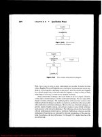
FIGURE 30.6
Selecting a straight edge for a conical part
Select one of these edges in the
Fixed Face/edge selection box
859
Using the Insert Bends Method for Sheet Metal Parts
30
41_080139 ch30.qxp 3/26/07 5:38 PM Page 859
Mixing Methods
Once you have used the Insert Bend tool on a part, it is not automatically excluded from using
some of the more advanced tools that are available through the Base Flange method, unless it is a
cylindrical or conical part. A Flat Pattern feature is added to the bottom of most feature trees, and
the presence of this feature is what signifies that the current part has now become a sheet metal
part to the Base Flange features.
However, it is recommended that you avoid mixing the different techniques to flatten parts, for
example, suppressing bends under Flatten and Process Bends, as well as using the Flat Pattern.
Tutorial: Working with the Insert Bends
method for sheet metal parts
The Insert Bends method has been relegated mainly to duty for specialty functions. Gain an under-
standing of how this method works by following these steps:
1. Create a new blank part.
2. On the Top plane, open a sketch and sketch a rectangle centered on the Origin 12 inches
in the Horizontal direction and 8 inches in the Vertical direction.
3. Extrude the rectangle 1 inch with 45 degrees of draft, Draft Outward, in Direction 1, and
in Direction 2 extrude 2 inches with no draft. The two directions should be opposite
from one another.
4. Shell out the part to .050 inches, selecting the large face on the side where the draft has
been applied. The part should now look like Figure 30.7.
FIGURE 30.7
The part as of step 4
860
Working with Specialized Functionality
Part VII
41_080139 ch30.qxp 3/26/07 5:38 PM Page 860
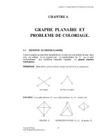
5. Use the Rip feature to rip out the four corners. Allow the Rip to rip all corners in both
directions. The part should now look like Figure 30.8.
FIGURE 30.8
Ripping the corners
6. Draw a rectangle on one of the vertical faces of the part, as shown in Figure 30.9.
FIGURE 30.9
Adding a sketch for the cut
Completed rip
861
Using the Insert Bends Method for Sheet Metal Parts
30
41_080139 ch30.qxp 3/26/07 5:38 PM Page 861
7. Use the sketch to create a Through All cut in one direction. Notice that the Normal Cut
option is on by default. Examine the finished cut closely; notice that it is different from the
default type of cut because it is not made in a direction normal to the sketch, but rather in
a direction normal to the face of the part. Details of this are shown in Figure 30.10.
FIGURE 30.10
Using the Normal Cut option
862
Working with Specialized Functionality
Part VII
41_080139 ch30.qxp 3/26/07 5:38 PM Page 862
8. Click the Flatten button on the Sheet Metal toolbar. Notice that the Flat Pattern feature
becomes unsuppressed and that the Bend Lines sketch under it is shown. This works just
like it did in the Base Flange method. The finished part is shown in Figure 30.11.
FIGURE 30.11
The finished part with the Flat Pattern feature unsupressed
Summary
The Insert Bends method was convoluted, requiring a lot of jumping around between rollback
states, and reordering to place features in the proper order so that everything appears on the flat
pattern where it belongs. The new tools are far easier to use, but do not replace all of the function-
ality of the old technique.
863
Using the Insert Bends Method for Sheet Metal Parts
30
41_080139 ch30.qxp 3/26/07 5:38 PM Page 863
41_080139 ch30.qxp 3/26/07 5:38 PM Page 864
W
eldments in SolidWorks are built on driving structural profiles
along sketch entities in a multibody part environment.
Weldment members can be curved, you can make them using
standard or custom profiles, and you can build them from both 2D and 3D
sketches. A Cut list within the part keeps track of how much of each profile
is needed to fabricate the weldment. Weldments are specialized parts that are
similar in some ways to sheet metal parts.
You can use weldments for round or rectangular tubular structures, struc-
tures made from channels, flanged sections, standard or custom shapes, gus-
sets, and end caps, and they can also represent weld beads in the part. You
can also use weldments to create structures that are bolted together, struc-
tural aluminum extrusion frames, and vinyl window frames, and you can put
them into assemblies with other parts such as castings, sheet metal, and fab-
ricated plate.
Sketching in 3D
Three-dimensional sketching is important for creating weldments in
SolidWorks. Structural frames are a large part of the work that is typically
done using weldment functionality in SolidWorks, and frames are best repre-
sented as 3D wireframes. You can do this with a combination of 2D sketches
on different planes, with a single 3D sketch, or with a combination of 2D
and 3D sketches. If you have confidence in your ability to use 3D sketches,
then that is the best way to go. Three-dimensional sketches can be challeng-
ing, but they are certainly manageable if you know what to expect from
them.
865
IN THIS CHAPTER
Sketching in 3D
Using Weldment tools
Using non-structural
components
Using sub-weldments
Using Cut lists
Creating Weldment drawings
Tutorial: Working with
weldments
Using Weldments
42_080139 ch31.qxp 3/26/07 5:39 PM Page 865
Earlier chapters discuss the tools that are available for 3D sketches; this chapter covers techniques
for 3D sketching.
Navigating in space
When working in a 3D sketch, the cursor and Origin initially look as shown in Figure 31.1. The
large red Origin is called the space handle, with the red legs indicating the active sketching plane.
Any sketch entities that you draw lie on this plane. The cursor also indicates the plane to which the
active sketching plane is parallel. The XY graphic shown in Figure 31.1 does not mean that the
sketch is going to be on the XY plane, just parallel to it.
FIGURE 31.1
The space handle and the 3D sketch cursor
Pressing the Tab key causes the active sketching plane to toggle between XY, YZ, and ZX. The
active sketching plane indication does not create any sketch relations; it just lets you know the ori-
entation of the sketch entities that are being placed. If you want to create a skew line that is not
parallel to any standard plane, you can do this by sketching to available endpoints, vertices,
Origins, and so on. If there are not any entities to snap to, then you need to accept the planar
placement, turn off the sketch tool, rotate the view, and move one end of the sketch entity.
An excellent tool to help you visualize what is happening in a 3D sketch is the Four Viewport view.
This divides the screen into four quadrants, displaying the Front, Top, and Right views in addition
to the trimetric or isometric view. You can sketch in any of the viewports, and the sketch updates
live in all of the viewports simultaneously. This arrangement is shown in Figure 31.2. You can eas-
ily access the divided viewport screen by using buttons on the Standard Views toolbar or the view
selector in the lower-left corner of the graphics window. You can also manually split the screen by
using the splitter bars at the lower-left and upper-right ends of the scroll bar areas around the
graphics window. These window elements are also described in Chapter 2.
When unconstrained entities in a 3D sketch are moved, they move in the plane of the screen. This
can lead to unexpected results when viewing something at an angle, moving it, and then rotating
the view, which shows that it has shot off into deep interplanetary space. This is another reason for
using the Four Viewport view, which enables you to see what is going on from all points of view at
once.
866
Working with Specialized Functionality
Part VII
42_080139 ch31.qxp 3/26/07 5:39 PM Page 866
FIGURE 31.2
The Four Viewport view
Sketch relations in 3D sketches
Sketch relations in 3D sketches are not the same as in 2D sketches. Although vast improvements
have been made by the addition of relations such as Midpoint and Equal, other relations are miss-
ing, such as Symmetric and Pierce. Pierce is replaced by Coincident, because in 3D sketches, there
is no difference between Pierce and Coincident; this is because relations are not projected into a
plane the way they are in 2D. The Symmetric relation, however, is sorely missed.
On the other hand, several other relations are available in 3D sketches that are not found in 2D
sketches, such as AlongX, AlongY, AlongZ, and OnSurface.
As mentioned earlier, relations in 3D sketches are not projected like they are in 2D sketches. For
example, an entity in a 2D sketch can be made coincident to an entity that is out of plane. This is
because to make the relation, the out-of-plane entity is projected into the sketch plane, and the rela-
tion is made to the projection. In a 3D sketch, Coincident means Coincident, with no projection.
867
Using Weldments
31
42_080139 ch31.qxp 3/26/07 5:39 PM Page 867
As a general caution, keep in mind that solving sketches in 3D is more difficult than it is in 2D.
You will see more situations where sketch relations fail, or flip in the wrong direction. Angle
dimensions in particular are notorious in 3D sketches for flipping direction if they change and go
across the 180-degree mark. When possible, it is advisable to work with fully defined sketches,
and also to be careful (and conservative) with sketch relations.
For example, the sketch shown in Figure 31.3 cannot be fully defined without also overdefining
the sketch. The main difficulty is that the combination of the tangent arc and the symmetric legs of
the end brace cannot be located rotationally, even using the questionable reliability of 3D planes
that are discussed next. The only workable answer to this is to create a separate 2D sketch on a real
2D sketch plane, where the plane is defined by the elements of the 3D sketch. If you are interested
in examining this part in detail, then you can find it on the CD-ROM. The filename is Chapter 31 –
Cant Define.SLDPRT.
FIGURE 31.3
Three-dimensional sketches may be difficult to fully define.
Planes in space
Starting with SolidWorks 2006, it has been possible to create planes directly in 3D sketches. These
planes function in some respects like sketch entities, by following sketch relations. Sketches can be
created on these planes, and move with the planes. Having planes in the sketch also enables planar
sketch entities such as arcs and circles in 3D sketches.
This set of sketch entities
cannot be located rotationally
within the 3D sketch
868
Working with Specialized Functionality
Part VII
42_080139 ch31.qxp 3/26/07 5:39 PM Page 868
Unfortunately, there is a lot to watch out for with 3D planes, as they are called. The first thing to
watch out for is that they do not follow their original definition like normal Reference Geometry
type planes. Figure 31.4 shows the PropertyManager interface for creating 3D planes; however,
keep in mind that the plane does not maintain the original relation to these initial references. The
parent-and-child relations that SolidWorks users are used to are suspended for this one function,
or work in the reverse from what you normally expect.
FIGURE 31.4
The three-dimensional planes PropertyManager
Three-dimensional planes cannot be fully defined unless there is some sketch geometry on the
plane that is in turn related to something else. Relations cannot be applied directly to the plane
itself, only to other entities on the plane. Horizontal and Vertical relations of entities on the plane
are relative only to the plane and not to the rest of the part, and so making a line horizontal on the
plane does not mean anything when the plane rotates (which it is free to do until it is somehow
constrained to prevent this).
Beyond this, when a plane violates a sketch relation, the relation is not reported, which severely
limits the amount of confidence that you can place in planes that are created in this way.
869
Using Weldments
31
42_080139 ch31.qxp 3/26/07 5:39 PM Page 869
The basic recommendation on this tool is to either use it at your own risk, having been warned, or
simply to leave it alone. The preference is to use reference planes that are created in the familiar
and reliable way. Although this requires that the planes be made beforehand, it guarantees that the
planes will stay where you put them, or move in controllable ways.
If you choose to use these planes, to activate the plane for sketching, then you can double-click the
plane with the cursor, or select the plane and press the 3D Sketch On Plane button on the Sketch
toolbar. The plane is activated when it displays a grid. You can double-click an empty space to
return to regular 3D Sketch mode.
Planar path segments
Some path segments that are allowed in 3D sketches can only be used if they are sketched on a
plane. These entities include circles and arcs, and can include splines, although splines are not
required to be on a plane. It has already been mentioned that to sketch on a 3D Plane (a plane cre-
ated within the 3D sketch), you can simply double-click the plane.
To sketch on a standard plane or reference geometry plane, you can Ctrl-click the border of the
plane with the sketch entity icon active or double-click on the plane. The space handle moves,
indicating that newly created sketch entities will lie in the selected plane.
When sketching a rectangle, you are accustomed to getting horizontal and vertical rela-
tions on the lines of the rectangle, which orient it in space. When sketched on a selected
plane in a 3D sketch, the elements of a rectangle are given relations similar to those of a parallelogram,
where parallel and perpendicular relations are used instead of horizontal and vertical ones.
This is due in part to the nature of the 3D sketch, where horizontal and vertical relations are replaced
by AlongX, AlongY, and AlongZ.
Dimensions
Dimensions in 2D sketches can represent the distance between two points, or they can represent
the horizontal or vertical distance between objects. In 3D sketches, dimensions between points are
always the straight-line distance. If you want to get a dimension that is horizontal or vertical, you
should create the dimension between a plane and a point (the dimension is always measured nor-
mal to the plane) or between a line and a point (the dimension is always measured perpendicular
to the line). For this reason, reference sketch geometry is often used freely in 3D sketches, in part
to support dimensioning.
Using the Weldment Tools
Like the Sheet Metal tools, the Weldment tools in SolidWorks are specialized to enable you to cre-
ate weldment-specific features in a specialized environment. Everything starts from a sketch or set
of sketches representing the wireframe of the welded structural members.
CAUTION
CAUTION
870
Working with Specialized Functionality
Part VII
42_080139 ch31.qxp 3/26/07 5:39 PM Page 870
Weldment
The Weldment button on the Weldment toolbar simply places a Weldment placeholder in the
FeatureManager. This placeholder tells SolidWorks that this part is a special weldment part, much
in the way that the Sheet Metal feature in sheet metal parts is a placeholder, and denotes a special
part type. The Weldment feature moves to the top of the tree, regardless of when it is created in the
part history. If you do not create a Weldment feature manually, then one is automatically created
for you and placed at the top of the tree when the first Structural Member feature is created.
Structural Members are discussed next in this chapter.
This feature does not offer any special default settings, except for the ability to set custom proper-
ties that transfer to all Cut list items that are created in the current part, and the fact that the Merge
Result option is turned off by default in Weldment parts. The former is important when multiple
weldments go together to make an assembly. You can access the custom properties interface, shown
in Figure 31.5, through the Properties option on the Weldment feature RMB menu.
FIGURE 31.5
The Weldment Properties interface
Structural Member
A Structural Member is the basic building unit of weldments in SolidWorks. You can create a
Structural Member by extruding a profile along one or more path segments, and it may result in a
single body or multiple bodies. The path segments may be in the form of 2D or 3D sketches. A
Structural Member may use path segments from multiple sketches, and each selected sketch entity
must touch another selected sketch entity, although they do not need to touch end to end.
A single Structural Member feature may create multiple bodies, with each body corre-
sponding to a single cut length of stock. In other words, the feature name “Structural
Member” does not necessarily refer to a single piece of the weldment, although it may.
One limitation of the use of sketches in Structural Member features is that only two selected sketch
entities may intersect at any one location. For example, at each corner of a cube, three path seg-
ments intersect, and so you can only select two of those elements at one time to create a Structural
Member feature. Because each of the path segments requires a piece of metal, the leftover path seg-
ments may be used by a second Structural Member feature.
NOTE
NOTE
871
Using Weldments
31
42_080139 ch31.qxp 3/26/07 5:39 PM Page 871
When creating the sketch for the weldment, it is important to decide what the sketch represents.
For example, does it represent the centerline of the structural elements, or does it represent the
closest that the elements can be to one another or to something else? You can orient and position
structural shape profiles relative to the frame sketch in several ways, with positioning at the shape
centroid being probably the most intuitive for closed shapes, and a corner being most intuitive for
angle channels.
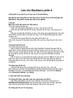
Figure 31.6 shows a single 3D sketch of a simple frame and a Structural Member feature in the
process of creation. You must select the standard first, then the type, and finally the size. A limited
number of profiles come with the software, and although it is very likely that you will need to cre-
ate some custom profiles; fortunately, they are very easy to create.
To access a large number of weldment profiles in various standards, open the Design Library and
select the SolidWorks Content icon. Under that, the Weldments folder has several zip files contain-
ing weldment profiles. Ctrl-click an icon to down load the file, and then extract the contents of the
zip file to the library location you have established for your weldment profiles.
FIGURE 31.6
A 3D sketch of a frame
Locating and orienting the profile
When you apply a profile to a path segment in a Structural Member feature, the profile must have
some relationship to the path segment. The default point where the path “pierces” the profile is at
the sketch Origin. To change the pierce point, you can click the Locate Profile button at the bottom
of the Structural Member PropertyManager, which zooms the view to present the profile sketch so
that you can select another sketch point to use as the pierce point. You can select any sketch point
872
Working with Specialized Functionality
Part VII
42_080139 ch31.qxp 3/26/07 5:39 PM Page 872
on the profile, including endpoints, sketch points, and virtual sharp points if they are present in
the sketch.
Profile sketches are generally surrounded by several sketch points, which may seem unnecessary
until you consider that you can use any of the points to position the profile. The Settings panel at
the bottom of the Structural Member PropertyManager is shown in Figure 31.7, and displays a
profile sketch with the interface.
FIGURE 31.7
Locating the profile
In addition to locating the profile sketch, you can also rotate the profile using the Angle field in
the Settings panel. This rotates all of the bodies that are created by the Structural Member feature
at the same time. In the example of the four-legged frame, if the legs are rectangular or circular,
they can all be created in the same Structural Member feature because they are all rotated in the
same way. However, if the legs were made from an asymmetrical shape such as an angle, then each
leg would need to be made using a separate Structural Member feature, with each leg rotated
differently.
Disjoint sketch segments
You can select disjoint sketch segments in a single Structural Member feature if they are parallel to
the first segment and use the same location and orientation. For example, in Figure 31.6, notice
the four angled supports in the corners attaching to the legs. Because they are parallel in pairs, all
four of these supports could not be made in a single Structural Member feature; however, they
could be made in two features or by one feature and a mirror. Later in this section, when those
path segments are actually used to place Structural Members, the additional requirement of using
an angle profile means that the profiles each need to be rotated differently from one another, and
thus cannot be used in a single Structural Member feature. Ultimately, the way to accomplish this is
by using one Structural Member feature and two Mirror features, thus mirroring the body that is
created.
873
Using Weldments
31
42_080139 ch31.qxp 3/26/07 5:39 PM Page 873
Custom profiles
Most of the custom profiles that you will need may be simply new sizes of existing profiles. You
can easily create a custom profile by opening an existing profile, editing it, and saving it under a
different name using the Save As command. It is important to note that when creating a weldment
profile, a sketch must be selected prior to initiating the Save As command. Weldment profiles are
Library Features, and use a *.sldlfp filename extension. Each size must be saved as a separate
library feature in order to appear in the selection list. While library features are configurable, the
configurations are not selectable for weldment profiles.
Other sources for custom profiles include 3D Content Central, which has a large number of erec-
tor-set aluminum extrusion profiles and the accessory hardware for those systems. Toolbox also has
a Structural Steel sketch generator, shown in Figure 31.8, which allows you to generate most stan-
dard shapes. If you have Toolbox installed on your system, then you can find this tool in the
Toolbox menu.
FIGURE 31.8
The Structural Steel sketch generator interface
As I have said throughout this book, weldment profiles are a great candidate for storing in your
special library folder, separate from the SolidWorks installation directory. To establish this library
location, you can go to Tools ➪ Options ➪ File Locations ➪ Weldment Profiles. Also keep in
mind that if you share design duties with other users, then the library location should either be
shared among users on a network, or the libraries should be copied to each user’s local library. You
can also share library data through a Product Data Management, or PDM, program.
If you are creating completely new custom profiles, then remember that when locating the profile
relative to the path segments, you can use any sketch point. As a result, you should provide ample
874
Working with Specialized Functionality
Part VII
42_080139 ch31.qxp 3/26/07 5:39 PM Page 874
selections for pierce points. Virtual sharps function well around filleted corners, as well as sketch
points at the centroid of a shape.
In addition to sketch geometry, the library part files should also contain custom property informa-
tion about the structural shape, such as part number, supplier, material, and so on. This informa-
tion propagates to the Cut list.
Corner treatments
Any intersection of sketch lines at mutual endpoints within a single Structural Member feature,
except as noted in this section, creates a situation that requires that the corners be cut to match.
Figure 31.9 shows an example of the three options that are available when lines meet at right
angles.
FIGURE 31.9
Corner treatment options
To access the toolbar with the Corner Treatment options, you can click the pink dot at the intersec-
tion of the path segments. Default corner treatment settings are made in the Structural Member
PropertyManager, but they may need to be adjusted individually.
Two situations do not require corner treatments. The first situation is when a line intersects another
line at some location other than an endpoint in the same Structural Member feature, for example, a
support meeting the main member in the middle. In this situation, the member that ends in the
middle of the other member is trimmed to a butt joint. The second situation is when an intersect-
ing member is created by a later Structural Member feature. This situation is dealt with by using
the Trim/Extend function, which is described later in this chapter.
You may encounter a situation where it seems like a good idea to create collinear sketch
segments. In a typical extrusion, the faces created from collinear lines are simply
merged together as one. However, in a weldment, this does not work when it is done in a single fea-
ture. In order to create Structural Members on collinear sketch lines, you must either extend one line
to encompass the length of both lines or do the work in two separate Structural Member features.
NOTE
NOTE
875
Using Weldments
31
42_080139 ch31.qxp 3/26/07 5:39 PM Page 875
Arc segments
When arc sketch segments are part of the selection for a Structural Member, a Merge Arc Segment
Bodies option displays after the selection box in the Selections panel. This means that any tangent
arc segment will be joined to the entities to which it is tangent, but any non-tangent entities will
create separate bodies.
A tangent arc is illustrated in the curved leg brace shown in Figure 31.10, along with the Merge
Arc Segment Bodies option in the PropertyManager.
FIGURE 31.10
A tangent arc segment used in a Structural Member feature
If the Merge Arc Segment Bodies option is not selected, then a separate body is created for arc seg-
ments. The Merge Arc Segment Bodies option applies to the whole feature, and cannot be set selec-
tively for individual arc segments within the selected sketch entities; it is either on for all or off for
all. If some arc segment bodies should be merged and others should not, then you should create
separate Structural Member features.
876
Working with Specialized Functionality
Part VII
42_080139 ch31.qxp 3/26/07 5:39 PM Page 876
It is also a curious limitation that only one arc may be selected if the selected path segments are
disjoint. For example, the two arcs for two J shapes that do not touch could not be selected in the
same Structural Member feature. The obvious workaround is to create two separate Structural
Member features.
Patterning and symmetry
Bodies created by the Structural Member feature can be patterned and mirrored. Remember that
there is a difference between patterning features and patterning bodies. The Move/Copy Bodies fea-
ture is also appropriate for creating bodies to be used in the weldment, although the Structural
Member feature does not create them directly.
I mention this to emphasize the point that sketching with symmetry is still important, although it
is far more difficult with 3D sketches than with conventional 2D sketches. This is due to the lack
of the Symmetry constraint and the ability to mirror sketch entities in 3D. I also mention this
because in larger weldments (or when using slower computers), performance may be an issue, and
mirroring or patterning bodies is certainly a performance enhancement over building parametric
features.
Configurations
When you start creating a weldment, SolidWorks automatically creates a derived configuration.
Both configurations are named Default, but they have different descriptions. The parent configura-
tion description is As Machined, and the derived, or indented, configuration description is As
Welded.
This arrangement holds true for any additional top-level configurations that you create in the part;
they will all get the description As Machined and inherit an identically named derived configura-
tion with the description As Welded. These configurations are meant to help you create drawings
where the raw weldment is distinguished from the weldment after it has been machined, ground,
and drilled.
Trim/Extend
In situations where you must create multiple Structural Member features, thus creating intersecting
bodies, the interferences must be dealt with using the Trim/Extend feature. An example of this is
shown in Figure 31.11. The legs and braces shown are all being trimmed by a single face on the
bottom side of the rectangular section of the frame, where the small arrow appears.
Bodies may be trimmed by planar faces or other bodies. Bodies may also be trimmed before they
are mirrored or patterned. Although trimming with faces gives better speed results, it may not give
the same geometrical results.
The Extend option enables either trimming or extending, as appropriate. If the Extend option is
not selected, then trimming is the only action available.
877
Using Weldments
31
42_080139 ch31.qxp 3/26/07 5:39 PM Page 877
FIGURE 31.11
Using the Trim/Extend feature
Trim with
planar face
Body to
be trimmed
878
Working with Specialized Functionality
Part VII
42_080139 ch31.qxp 3/26/07 5:39 PM Page 878
End Cap
The End Cap feature closes off an open-ended Structural Member. You can add multiple end caps
without re-initiating the feature by using the push-pin icon in the PropertyManager. The
PropertyManager and the end product are shown in Figure 31.12.
FIGURE 31.12
Using the End Cap feature
The end cap sits on the outside face of the member, and overlaps the thickness of the member by
the inverse of the Thickness Ratio that is applied in the Offset panel. If the Use Thickness Ratio
option is turned off, then it functions as an offset from the outer faces of the member from which it
is created. When this option is turned on, the thickness ratio can range from zero to one. For a
value of zero, it is flush with the outer faces of the member, and for a value of one it is flush with
the inner faces of the member.
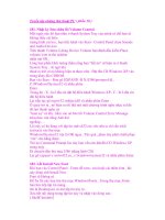
Gusset
The Gusset feature creates a three- or five-sided gusset in a corner between Structural Members, as
shown in Figure 31.13. You can place the gusset at specific locations along the edge in the corner,
or offset it by a specific dimension in a specific direction by using the settings in the Parameters
panel. You can control the size and thickness of the gusset in the Profile panel. There is no sketch
for this feature type; it is simply created from the parameters that you enter in the PropertyManager
interface. Again, if you need to make multiple Gusset features in succession, then you can use the
push-pin icon to keep the interface displayed until you close it by clicking the red X icon.
879
Using Weldments
31
42_080139 ch31.qxp 3/26/07 5:39 PM Page 879
FIGURE 31.13
Using the Gusset feature
Fillet Bead
The Fillet Bead feature is somewhat limited in its ability to make realistic weld beads on a weld-
ment part. To start with, it is limited to fillet welds, and does not weld around commonly found
situations such as that shown in Figure 31.14. It works best where flat faces butt up against one
another cleanly, with enough space all the way around them for the weld bead. It is often suggested
that for drawings, you are better to leave the Fillet Bead feature off of the model and simply to use
weld symbols or caterpillars to represent the weld bead.
880
Working with Specialized Functionality
Part VII
42_080139 ch31.qxp 3/26/07 5:39 PM Page 880
FIGURE 31.14
Using the Fillet Bead interface
Using Non-Structural Components
Non-structural components are frequently needed in weldments, and include items such as feet,
plates, brackets, mounting pads, castings, and other items. Simpler items that can be easily modeled
in place can be placed directly into the weldment part. You can also insert parts into the weldment
using the Insert Part feature, and move them into place by using dimensions or mates. In general, if
any item is actually welded into the weldment, then you are recommended to place it in the weld-
ment part; however, items that are bolted on should probably be placed into an assembly. Of course,
this probably depends more on your company’s documentation standards, part-numbering stan-
dards, and assembly processes than on software capabilities.
When adding a plate such as the footplate shown in Figure 31.15, the geometry is added using the
standard Extrude feature, except that the Merge option is turned off by default. This ensures that
non-structural components that are manually modeled, such as this part, are created as separate
bodies, and not merged together with the existing structural items.
881
Using Weldments
31
42_080139 ch31.qxp 3/26/07 5:39 PM Page 881
FIGURE 31.15
A foot plate added to the weldment
It is recommended that similar elements of the weldment be grouped together. For
example, you can create the tubular members in a group, and the angle members in
another group, as well as non-structural components, gussets, weld beads, and end caps in groups or
folders of their own. This can help to keep a busy part organized.
Using Sub-Weldments
From a modeling point of view, sub-weldments are generally used for either organizational or per-
formance reasons to group together elements of a weldment or to break a larger weldment into
more manageable pieces. This is in much the same way that subassemblies are created for the same
purposes within larger assemblies. From a fabrication point of view, sub-weldments are also used
to break a large weldment into pieces that can be transported or handled.
To create a sub-weldment, you can select several bodies from the Cut list, and then select Create
Sub-Weldment from the RMB menu. (You can also select the bodies from the graphics window if
you use the Select Bodies selection filter.) This creates a separate folder for the sub-weldment bod-
ies. You can then RMB click the sub-weldment folder and select Insert Into New Part.
Using Cut Lists
The Cut list that is maintained in the model FeatureManager is simply a replacement for the Solid
Bodies folder. It has most of the same functionality as the Solid Bodies folder, as well as a few addi-
tional items. The two symbols shown before the Cut Lists title show the folder symbol for the
folder when it requires an update (top) and after the update has been performed (bottom). Cut lists
are updated automatically when a drawing that uses the Cut list is accessed.
You can access the Update command from the RMB menu of the Cut List folder. Figure 31.16
shows the result of the update. The weldment solid bodies are broken down further into subfolders
NOTE
NOTE
882
Working with Specialized Functionality
Part VII
42_080139 ch31.qxp 3/26/07 5:39 PM Page 882
that reflect quantities of identical bodies. Notice that the weld beads at the bottom of the list are
not in a folder.
FIGURE 31.16
The Cut list in the model FeatureManager
Custom properties
Custom properties that come from profile library features, and the Weldment feature in a part, con-
tribute to the information that can appear in a Cut list on a drawing. You can access custom prop-
erties for individual Cut list items from the Cut List Item’s RMB menu, as shown in Figure 31.17.
FIGURE 31.17
The Cut List Custom Properties interface
883
Using Weldments
31
42_080139 ch31.qxp 3/26/07 5:39 PM Page 883