The Essential Guide to Flash CS4 friends of ED ADOBE LEARNING LIBRARY PHẦN 4 pdf
Bạn đang xem bản rút gọn của tài liệu. Xem và tải ngay bản đầy đủ của tài liệu tại đây (1.14 MB, 43 trang )
DRAW ME A PICTURE: USING THE DRAWING TOOLS
107
4
Figure 4-34. Using an oval to aid design
You may need to turn snapping off by toggling the snap icon to the off state. In the on
state, the snap icon looks like this:
; and in the off state, it looks like this: .
12. Double-click the gray oval to select it.
Double-clicking objects in Flash selects both the shape
and its outline.
13. Copy and paste another oval, and place it further along the curve of the G. You can
also hold down Alt as you drag the oval, as this will have the same effect as copy/
paste.
14. Continue to place more ovals at major junctions in the letter shape, as shown in
Figure 4-35. Try to use as few as possible while still keeping true to the letterform.
Use the
Transform tool to shrink or grow the oval to fit the shape if you have to.
Figure 4-35. Placing ovals at major
junctions on the G in the logo
THE ESSENTIAL GUIDE TO FLASH CS4
108
15. Lock the oval layer and name it oval using the process described earlier.
16. As a final step, save the Flash CS4 document as caja)hkck*bh].
With the ovals in place, we are now ready to construct the typography. The ovals are used
as construction lines to keep the letters formed in correct proportion. This assures consis-
tency and quality of the type.
Mastering the Pen tool
The Pen tool is one of the most important inventions for creating vector illustrations. It
allows for fast and accurate line work. When you master the
Pen tool, digital illustration
becomes a whole lot easier. The
Pen tool also has a counterpart, the Sub-selection tool.
The
Sub-selection tool allows you to move and manipulate pivot points created by the Pen
tool.
The
Pen tool can be used to draw two types of lines: straight lines and curves. Straight lines
are plotted using a two-click process. Click the starting point. As you move the mouse
outward, a line will follow the pointer. Click again to create an endpoint. To draw curves,
you keep the mouse button held down when you click the second point. As you drag the
mouse, the line will curve in response to the movement. Usually you will have to draw an
initial point before making a curve. Sometimes the curve will not seem to fit, no matter
which way you push or pull. If this happens, you can access the
Convert Anchor Point tool
from the
Pen tool menu in the Tools panel. This tool will toggle between giving the line a
sharp curve and a smooth curve.
Once you have drawn your outline most of the way around the first letter, you can close
the shape by clicking back on the first point you made. The
Pen tool icon changes to dis-
play a small o when you mouse over the initial point, indicating that you can close the
shape by clicking that point
. Figure 4-36 shows the Pen tool options.
Figure 4-36. The Pen tool options
You can use the Pen tool to create crisp, hard-edged vector art.
Let’s attempt to trace the letterform in the sketch, paying careful attention to following
the outer shape of the ovals. Create a new layer and lock all the layers underneath. Ensure
that snapping is on.
In Flash, snapping helps you to align elements on the stage.
DRAW ME A PICTURE: USING THE DRAWING TOOLS
109
4
You can continue the exercise from its last save point if you wish, but if you haven’t com-
pleted the exercise and you want to start from this point, load the file 0)/*bh], which is
available for download from the friends of ED website.
1. Zoom in to the letter G so that it occupies most of your screen, as you did in the
first exercise creating the logo.
2. Select the Pen tool. Starting from the uppermost oval, click a point on the top edge
of the letter G.
3. Working clockwise, click and drag a curve along the oval to where the oval meets
the sketch underneath. Try to use the fewest points possible while still keeping the
integrity of the shape.
4. Click and drag curves along the entire outline of the letter. There should be no
straight lines. Instead of using the scrollbars to move around the stage, try holding
the space bar down to temporarily activate the
Hand tool. The mouse will change
into a hand. This hand will let you grab the stage and move it around.
5. The curves don’t have to perfectly follow the sketch. Try to keep the curves fluid.
Tracing around an oval will take four clicks.
During the tracing, you may have to convert the anchor point. To do so, mouse over the
last point you made until you see the upside down V. When the icon changes, click again
to convert the anchor point.
Anchor points are points that are stationary when you manipulate an object by
stretching, skewing, scaling, or mirroring.
At any time, you can stop and edit the path by choosing the Sub-selection tool. Use this
tool to move the point around, and also to change the angles of curves. Observe that you
can also select multiple points on the curve by either dragging a selection or holding down
Shift and clicking.
To resume drawing the path you were working on, select the
Pen tool and continue to
draw.
6. Follow the outer edge all the way around until the Pen tool meets back up with the
first point you drew. When you mouse over the initial point, the icon will change
once again to display a small o
. This will ensure that you complete the shape. If
you don’t complete the shape properly, you may not be able to fill it with color at
a later stage.
Your completed G outline should look similar to Figure 4-37.
THE ESSENTIAL GUIDE TO FLASH CS4
110
Figure 4-37. Outline of the gooey letter G
7. Select the Paint Bucket tool from the Tools panel, as shown in Figure 4-38, and fill
the shape with color by clicking in the middle of the outline.
Figure 4-38. The fill tools
Your completed G should appear similar to Figure 4-39.
Figure 4-39. Your filled G
DRAW ME A PICTURE: USING THE DRAWING TOOLS
111
4
Now be brave and finish the rest of the words Gene and Envy using the same process.
Notice that you will only have to create an outline for the e, n, v, and y. You can copy/
paste and transform the E and the other N.
We’ll start by temporarily hiding the current layer by clicking the hide dot in the timeline.
Remember to turn snapping off.
1. Unlock the oval layer. Copy/paste more ovals in meaningful spots along the sketch,
as shown in Figure 4-40.
Figure 4-40. Ovals used to construct the letters
2. Once the ovals are in place, lock the layer, turn snapping back on, and then start
tracing.
3. Use the sketch as a round placement guide. Good-looking typography has an ele-
ment of consistency. Remember this when positioning your ovals. The tops of the
n, v, and y have the ovals placed the same distance apart.
If you copy/paste from one letter to another, you will end up
with some uniformity, which is nice.
When the letters are fully drawn, you will need to look at the proportion and placement.
Obviously it is hard to get these two things perfect on a sketch, as sketches are only meant
to be rough guides. Try to ensure that all the characters are the same height. To visually do
this, activate the rulers by choosing
Rulers from the View menu, as shown in Figure 4-41. A
horizontal ruler will appear at the top of the stage, and a vertical ruler will appear to the
left of the stage.
THE ESSENTIAL GUIDE TO FLASH CS4
112
Figure 4-41. Activating the rulers from the
View menu
You can also use guides to visually align objects on the stage. You place guides on the stage
by clicking a ruler and dragging a guide outward and into an appropriate position. In this
case, drag two horizontal guides out to the bottom and top of the lettering. The G and the
E are almost 20% bigger than the other letters. This helps to improve readability and form.
When creating this sketch initially, I had a happy accident. As I drew over the y,
the bottom of it reminded me of a tentacle. So, using the v shape I had just cre-
ated, I copied another one and I added a descender to the letterform. Once the
tail was drawn, I then added the little oval suckers.
The finished Gene and Envy letters should look like Figure 4-42.
Remember to save your work regularly!
DRAW ME A PICTURE: USING THE DRAWING TOOLS
113
4
Figure 4-42. Lettering with the Pen tool
In the Gene with Envy logo, you’ve reused the letters E and N. Also, the V has been
reused and slightly manipulated to form the basis of the Y. Be aware of shortcuts
such as this, as they are often time saving, which can be very important on jobs
where a client is paying you by the hour to complete something.
We will continue with the type by drawing the with letters using the Rectangle and Oval
tools. We will build the type up with modular pieces.
1. Start by locking the current shape layer and renaming it shape.
2. Click the New Layer button on the timeline and call it with.
3. While you are in the Merge Drawing mode, use the Rectangle tool, find some empty
space, and draw a skinny rectangle, as shown in Figure 4-43.
4. Using copy/paste (or holding down Alt as you drag), arrange a series of seven rect-
angles, as shown in Figure 4-44. These will form the vertical pieces of the type.
Figure 4-44. Seven skinny rectangles
Figure 4-43.
A skinny
rectangle
THE ESSENTIAL GUIDE TO FLASH CS4
114
5. Copy another rectangle and rotate it 90°. Copy two additional rectangles. Place
these rectangles along the bottom of the W, along the top of the T, and across the
middle of the H. Trim any excess bits as you go.
The word with in the logo should look something like Figure 4-45.
Figure 4-45. The completed with
6. Now select the Ink Bottle tool in the Tools panel and create an outline around the
rectangular type by clicking each of the shapes that make up the word. Move the
letters left and right so that the gaps between them (the kerning) are in proportion.
Try not to leave big holes between letters.
The final with should look like Figure 4-46.
Figure 4-46. The final with
7. Select the whole word and move it down into place between the Gene and the
Envy, as shown in Figure 4-47.
Figure 4-47. The final typography
DRAW ME A PICTURE: USING THE DRAWING TOOLS
115
4
A faster technique could have also been to use a text field and a font to generate
the with vector art. Although this would not have looked as unique, it could have
made the logo creation process faster.
To create vector graphics from text fields, first select the
Text tool. Type out the
text you would like to use and then format it. After you have finished with the
formatting, make sure it is selected, and then go to
Modify ¢ Break Apart or press
Ctrl+B (or Cmd+B on the Mac). This will pull the group of letters apart. These
individual letters are not in an editable form. Use the Break Apart command once
more to convert the font into an editable vector graphic.
Finally, we will move on to the graphical element and the freehand tools. As a final exer-
cise with the drawing tools, we will look at the
Brush and Pencil tools. First, we’ll paint the
outline of the snail using the
Brush tool.
1.Create a new layer and name it snail.
2.Select the Brush tool, as shown in Figure 4-48.
Figure 4-48. The Brush tool
3. Use the Zoom tool or the keyboard shortcuts (Ctrl/Cmd and
+/-) so that you can fit the whole sketch vertically on the
screen.
4. Choose a brush that is smaller than the line weight on the
sketch.
Brush sizes can be changed via a drop-down
menu in the
Tools panel, which looks like
Figure 4-49.
5. Use the Brush tool to paint a fluid line over the top of the
sketch, as shown in Figure 4-50. You use the
Brush tool to
draw the outlines of the snail, because the
Brush tool gives
you the option to paint what looks like a variable-width
stroke. Variable-width strokes offer charm and character,
while constant-width strokes can look flat and lifeless. It is
impossible to achieve this style with the
Pen or Pencil tools,
which can only create constant-width strokes.
Figure 4-49.
Choosing the
correct brush size
THE ESSENTIAL GUIDE TO FLASH CS4
116
Figure 4-50. Choose a smaller brush size
to paint the linework.
When you have finished the outline of the snail, hide the sketch layer, and you will be
presented with an image similar to Figure 4-51.
Figure 4-51. The final snail
The Eraser tool may come in handy along the way. You can rub out lines that don’t feel
right or line work that is spiky. When you have finished, double-click the snail to select it
all. Smooth any wonky lines by clicking the
Smooth button . The more you click the
DRAW ME A PICTURE: USING THE DRAWING TOOLS
117
4
button, the smoother and simpler the shape becomes. When you are finished, change the
color of the snail to the dark color of the text outline.
Another time saver is the Trace Bitmap command. If you can draw or find an
image you are after, Trace Bitmap will convert the image into a vector shape for
you. Once your image is highlighted, you can find the Trace Bitmap command in
Modify ¢ Bitmap ¢ Trace Bitmap.
Pulling it all together
Move the snail up from the type to give it some breathing space. It should now look similar
to Figure 4-52.
Figure 4-52. Final snail with final type
Notice that the darker color of the snail dominates the logo. Return some balance to the
type by using the
Brush tool to paint shadow under the letters. Use the Paint Bucket tool
to fill the snail’s shell with a light gray. Fill the snail and its eye with white. The logo has
been drawn on a white background. If the logo was moved over a colored background, the
color would show through the eye. This is why you apply a white fill to the eye.
Create a new layer and name it
shadows. We want the shadows to appear under the type, so
drag the shadow layer to sit under the shape layer. Use the
Brush tool with the darker color,
similar to how you painted the snail. This time just use one thicker brush and follow the
curve under the letters. The logo with shadows under the text should look like Figure 4-53.
THE ESSENTIAL GUIDE TO FLASH CS4
118
Figure 4-53. Almost-final logo
Finally, you will add a ground plane line as a finishing touch. The Pencil tool is used for
drawing lines, and in particular, outlines for shapes. The
Pencil tool properties are shown in
Figure 4-54. Note that the
Pencil tool could have been used to draw the snail, but doing so
would have resulted in a constant-width stoke. A constant width can make your illustration
look flat, computerized, and lifeless (not quite the feel we’re trying to portray in the logo).
This is why the
Brush tool was used to draw the snail outlines.
The
Brush tool is traditionally used to paint fills and splashes of color. However, using the
Brush tool makes it easier to draw variable-width strokes, thus enhancing the hand-drawn
style of illustration.
Figure 4-54. The Pencil tool options
DRAW ME A PICTURE: USING THE DRAWING TOOLS
119
4
We will now draw the ground line below the snail.
1. With the logo document opened, completed to the last exercise, create a new layer
and name it
ground. The ground line will be drawn using a very long, thin outline.
2. Starting from the left side, draw a line that roughly follows the tops of the lettering.
3. When you get to the right side, draw down and then head back to the start and
close the loop. Fill the outline using the same dark green color.
Color me bad
The shop logo should convey a sense of life, a sense of bacterial infection. This has been
done using fluid and organic forms. To continue with the “living” theme, you will need to
splash around the color green—three yucky, stinky, slimy greens. First, choose a dark
green for the outline of the snail—a good choice would be the hex RGB color #003300.
You may need to apply color to the outline of the letters using the
Ink Bottle tool. When
using the
Ink Bottle tool, you are also able to change stroke settings, but for this exercise
we want to keep the default. Ensure you use the original settings of a 1.00 point stroke and
a style of solid. I created a
highlights layer and painted a few quick horizontal strokes of
light green. This gave the type and shell a little added depth.
You will need to download the final 0)bej]h*bh] file to see the where to apply the three
green colors, and to see an example of color choice. The logo is now complete, as shown
in Figure 4-55.
Figure 4-55. The final logo
You have just witnessed how to make an idea come to life. The design process is a dynamic
creature. The initial sketch looked quite different from the final logo. Some wise advice is
to not spend too much time on the initial sketch, as the final outcome will most likely
change (remember the design process from Chapter 2).
THE ESSENTIAL GUIDE TO FLASH CS4
120
Not only have you just learned some practical uses of the Flash drawing tools, but you now
have a funky piece of vector art to use throughout the remainder of the book.
Summary
Flash CS4 provides all of the drawing capabilities Flash designers need to bring their ideas
to life. In this chapter, you have learned about the drawing tools and symbols, and have
used them to create a logo that will form the basis of the site’s design. Don’t be afraid to
experiment with the different tools until you find an effect that is right for you.
It’s important not only to understand the techniques for building logos and graphics, but
the commercial realities of why you build them. As the Internet becomes more and more
an example of everyday advertising, it’s important that you know how to achieve cut-
through in the plethora of competing advertisements and websites out there. Understanding
how to represent your company graphically via the creation of relevant and unique logos
and marketing collateral is the first step in achieving commercial success.
In Chapter 5, you will be expanding upon this knowledge and learning how using these
tools can really bring your Flash animations to life.
CHAPTER 5
FILTERS AND BLENDS
THE ESSENTIAL GUIDE TO FLASH CS4
124
In Chapter 4 we explored how to create graphics with the drawing tools. In this chapter you
will learn quick and effective ways to enhance your graphics using Flash’s built-in filters and
blends.
Filters and blends can be a blessing to Flash designers who are required to output high-
quality Flash designs and movies in relatively short times. Using preset filters and blends
enables you to produce quality designs without having to reinvent the wheel every time
you want to use a particular effect.
They are particularly useful tools when you have clients that you create Flash movies for
regularly. You can incorporate the blends and filters typically used for the client into their
corporate guidelines. This then becomes a resource for the design team, and ensures that
any creative assets produced are within specifications.
What are filters?
Filters are used to create special effects. In photography terms, filters are usually transpar-
ent attachments that screw into the top of a lens, varying the way light is captured by the
camera. In Flash CS4, filters are used to enhance images, movie clips, buttons, and text
objects by applying an effect to your artwork. The greatest feat of all is the ability to com-
pose and animate filter effects without ActionScript!
There are two types of filters in Flash CS4, Pixel Bender and preset/animated. Preset/ani-
mated filters come standard with Flash CS4, while Pixel Bender filters are downloaded or
coded.
Pixel Bender filters
Pixel Bender is the name Adobe gives to its bitmap shading language. The language and
supporting IDE (Integrated Development Environment) allow Flash users to write their own
customized filters to utilize and share with the world.
Pixel Bender allows you to write algorithms and processes to affect an image at the funda-
mental pixel level. Imagine you had a photography website and you wanted to make a
Flash component that would allow a user to upload a color photo and then convert it to a
black-and-white one. Pixel Bender allows you to dynamically assess images at a pixel level.
The filter you write could grab all the red and green pixels and turn those white. It could
then turn all the blue pixels black. The result would be a black-and-white variation of the
original image.
Pixel Bender is also a versatile shading-language library that can be used in other motion-
video software, such as Adobe After Effects. Its versatility also means that Flash users can
share custom-created filters. The beauty of this open system is not only in the customiza-
tion and personal reuse of filters, but also in the community. Many websites now host
custom filters that other creative people have written for you. Adobe Exchange is a place
where developers can share their custom-developed filters for Adobe products. Simply
FILTERS AND BLENDS
125
5
search Adobe Exchange Pixel Bender in your search engine, or visit sss*]`k^a*_ki+
_bqoekj+at_d]jca+ej`at*_bi;arajp9lnk`q_pDkia"at_9.2.
The filters are made accessible using ActionScript. You can write your own filters and func-
tions or utilize the predefined Pixel Bender functions using the
Library Import command.
Writing your own filters is relatively ActionScript 3.0–intensive. ActionScript 3.0 will be
covered in greater detail in Chapter 8.
To download the Pixel Bender IDE, source files, and more tutorials, head to
dppl6++h]^o*]`k^a*_ki+`ksjhk]`o+letah^aj`an*dpih.
Preset/animated filters
The animated filters inherit their nature from the seven predefined graphical properties in
Flash CS4: the
Drop Shadow, Blur, Glow, Bevel, Gradient Glow, Gradient Bevel, and Adjust
Color filters
. These can be accessed in the same way as most other properties: using the
Filter tab in the Properties Inspector.
Filters can be applied to movie clips, buttons and text objects, shapes, sprites, videos, and
any other visible object on the stage. The filter properties for each object can be applied
by using the Properties Inspector or using ActionScript. You can apply multiple filters on
one object, too. The values of each filter can also be animated to produce flowing effects
that draw users in. Note that filters should be used sparingly for the sake of performance
on older, slower systems and also for aesthetics. Remember that less is usually more.
The preset filters have been designed for quick and easy operation. Filters can be applied
on the fly or varied during animation or ActionScript. These properties are
Blur, Bevel, Glow,
Shadow, Color, and Gradient. For instance, you could apply Blur to a button. The farther
away from the button the mouse moves, the greater the blur effect could be. Take a look
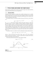
at Figure 5-1. It shows a white square that has been affected by each different filter.
Figure 5-1. A simple white square affected by various filters. Square a has no filters applied. Square
b has had a drop shadow applied to it, and square c has been blurred. Square d displays an outer
glow, and square e has had a colored bevel. Square f has had a bevel filter applied to it, square g
displays a gradient glow, and square h has been affected by applying multiple filters.
Figure 5-2 shows one of the characters developed for the exercises in this book, Tomtee. He
will be the guinea pig that we’ll apply filters to in this chapter. You can see in the figure the
huge difference applying filters to a graphic can make.
THE ESSENTIAL GUIDE TO FLASH CS4
126
Figure 5-2. Tomtee affected by each of the filters. Top row: drop shadow, blur, outer glow, and
colored bevel. Bottom row: beveled, gradient glow, adjusted color, and multiple filters.
Applying preset filters
Applying filters is easy. Select the movie clip, button, or
text. Then open the
Properties Inspector by either going to
Window ¢ Properties or using the shortcut Control+F3.
Click the
Filters drop-down to display the Filters section.
Notice the filter-settings icons at the bottom of the panel
(shown in Figure 5-3).
These icons control how you apply, remove, copy, and
paste all filter settings.
To apply a filter, click the
Add Filter button, and select the
filter you want to apply from the menu that appears. You are able to change all the values
of the filter in the
Properties tab. If you have more than one filter applied to an object, you
will need to click on that filter’s heading in the
Properties tab, as shown in Figure 5-4. Once
Figure 5-3. Filters settings
icons, from left to right:
Add Filter, Save Filter
Presets, Copy Filter, Enable
or Disable Filter, Reset Filter,
and Delete Filter.
FILTERS AND BLENDS
127
5
you’ve selected a filter, you can change all of its values. To remove the filter, click the
Delete Filter icon at the bottom of the panel.
Figure 5-4. Selecting a filter
You can also copy and paste filter settings so that you can apply the same settings to mul-
tiple objects. Do this by clicking the clipboard icon, as shown in Figure 5-5.
Figure 5-5. The clipboard icon allows
you to copy and paste filter settings.
The Enable or Disable Filter icon, denoted by an eye, will toggle the filter on/off. The Reset
Filter icon will return all the settings for the particular filter back to its original state.
We will now investigate each of the preset filters. To get the most out of the following
exercises, ensure that you have downloaded the source files from the download page for
this book at the friends of ED website, sss*bneaj`okba`*_ki.
The examples detailed in this chapter have been purposely exaggerated so
that we can demonstrate in black-and-white print the effects of blends and
filters. While the use of filters and blends is open to artistic interpretation, they
are used to quickly and easily lend depth to objects on the stage. Manipulate
the default filters and blends to produce custom ones to suit your client’s
needs. This enables you to streamline your production of Flash CS4 creative
assets to meet your client’s specifications in a timely and efficient manner.
THE ESSENTIAL GUIDE TO FLASH CS4
128
The Drop Shadow filter
Applying shadow to your designs can provide depth and a sense of added dimensionality.
Let’s investigate.
1. Open the exercises folder and open 5-01.fla in Flash CS4.
One of our loveable creatures, Tomtee, will load into the canvas. He is still line art at the
moment, so we must convert him into a movie clip before we can apply filters to him.
2. Click on the Selection tool in the tools panel to select the whole character and right-
click him to convert him to a movie clip symbol.
3. Give the movie clip the name of Tomtee, as shown in Figure 5-6.
Figure 5-6. Converting Tomtee to a symbol
4. Next, find the Properties Inspector and expand the Filters drop-down menu as shown
in Figure 5-7.
Figure 5-7. The Filter options live in the
movie clip’s Properties Inspector.
5. Select a drop shadow by clicking the Add Filter icon , then click on Drop Shadow
as shown in Figure 5-8.
FILTERS AND BLENDS
129
5
Figure 5-8. The Filter menu
Now that the Drop Shadow filter has been applied, you are able to alter the filter settings
as shown in Figure 5-9.
THE ESSENTIAL GUIDE TO FLASH CS4
130
Figure 5-9. Drop Shadow options
We’ll now take a moment to investigate the Drop Shadow options, as shown in Figure 5-9.
Blur X and Blur Y affect the edges of the shadow. Low settings yield a sharp outline, and
high settings yield softer diffused edges.
Strength defines how dark the shadow is. The
Quality setting governs the accuracy of the rendered shadow. High settings look much bet-
ter but add processing overhead, which adds to the resources required of the user’s com-
puter to display the published file.
Angle defines the angle from which the initial light source shines. Distance defines the dis-
tance of the shadow from the object that is casting it. Figure 5-10 shows two different
Distance settings. Knockout takes the initial shape and deletes it from the scene and
shadow, leaving an empty void where a body once lay. The
Inner Shadow setting creates a
negative shadow that can exist only in the object’s space.
Hide Object hides the movie clip
from the scene, leaving only the shadow behind.
Color is the basic color of the shadow. To
emulate real shadows, this should be set to a dark color, as shown in Figure 5-10. Play
around with the settings to get a good sense of what they all do.
Figure 5-10. Playing with the shadow settings
FILTERS AND BLENDS
131
5
The Blur filter
Anything that is out of focus is said to be blurred. Take a look outside the window and
notice how the distance blurs things far away. Like shadow, blur adds depth to designs.
Let’s explore this more.
1. Load the 5.02.fla file in Flash CS4.
You will notice that we have already made Tomtee into a movie clip symbol.
2. Select the movie clip character, then open the Properties Inspector, click the Add
Filter
button, and choose Blur from the filter drop-down, as shown in Figure 5-11.
Remember, the Add Filter button resides at the bottom of the Filter drop-
down in the Properties Inspector.
Figure 5-11. Choosing
the Blur filter
Once the Blur filter has been applied, we can play with the Blur X and Blur Y settings, shown
in Figure 5-12, to manipulate the extent of the blur.
Figure 5-12. The Blur settings panel
Blur X and Blur Y control the intensity of the blurring effect. Higher values create more of
a blurred look, while lower values retain a harder edge. Note the little chain links. These