SOIL ENGINEERING: TESTING, DESIGN, AND REMEDIATION phần 4 pps
Bạn đang xem bản rút gọn của tài liệu. Xem và tải ngay bản đầy đủ của tài liệu tại đây (3.23 MB, 27 trang )
©2000 CRC Press LLC
Upon completion of excavation, the stress condition in the soil mass will undergo
changes. There will be elastic rebound. Stress releases increase the void-ratio and
alter the density. Such physical changes will not take place instantaneously. If
construction proceeds without delay, the structural load will compensate for the
stress release. Thus, this will not be a significant amount.
6.4.4 P
ERMEABILITY
The permeability of the soil determines the rate of ingress of water into the soil,
either by gravitational flow or by diffusion, and these in turn determine the rate of
heave. The higher the rate of heave, the more quickly the soil will respond to any
changes in the environmental conditions, and thus the effect of any local influence
is emphasized. At the same time, the higher the permeability, the greater the depth
to which any localized moisture will penetrate, thus engendering greater movement
and greater differential movement. Therefore, the higher the permeability, the greater
the probability of differential movement.
6.4.5 E
XTRANEOUS
I
NFLUENCE
The above-mentioned basic factors, although difficult to predict, can be evaluated
theoretically. At the same time, extraneous influences are totally unpredictable. The
supply of additional moisture will accelerate heave, for instance, if there is an
interruption of the subdrain system to allow the sudden rise of a perched water table.
The development of the area, especially residential construction, can contribute to
a drastic rise of the perched water table.
Various methods have been proposed to predict the amount of total heave under
a given structural load. These include the double oedometer method, the Department
of Navy method, the South Africa method, and the Del Fredlund method. Recently,
with the advance of suction study, Johnson and Snethen claimed that the suction
method is simple, economical, expedient, and capable of simulating field conditions.
Some fundamental differences between the behavior of settling and heaving soil
are as follows:
1. Settlement of clay under load can take place without the aid of wetting,
while expansion of clay cannot be realized without moisture increase.
2. The total amount of heave depends on the environmental conditions, such
as the extent of wetting, the duration of wetting, and the pattern of
moisture migration. Such variables cannot be ascertained, and conse-
quently, any total heave prediction can only be speculation.
3. Differential settlement is usually described as a percentage of the ultimate
settlement. In the case of swelling soils, one corner of the structure may
be subject to maximum heave due to excessive wetting, while another
corner may have no movement. No correlation between differential and
total heave can be established.
©2000 CRC Press LLC
6.5 BUILDING ADDITIONS
Take great care when designing a new addition adjacent to or abutting an existing
building. This is especially important when the existing structure is owned by another
person. The new footings can exert an additional load on the existing footings and
cause settlement and cracking. Whenever possible, it is wise to consult with the
original engineer or the owner and study the initial design. If common walls are
used, eccentric loading will be expected. When the new and the old structures are
not on the same level, the lateral load from the existing structure should be consid-
ered. The bearing capacity as calculated for isolated footings should be drastically
reduced.
Similar precautions should be taken even when the new construction is isolated
from the existing structure. The owner of the neighboring structure can claim that
the weight of the new construction has caused the settlement of the neighboring
structure. It is therefore important to have a conference with the neighboring building
owners before starting the excavation. A prudent engineer takes pictures of the
neighboring structure to avoid possible future litigation. Documented photographs
can prove that the distress or cracking of the neighboring building existed before
the new construction.
Another important consideration in the design of footings is the property line.
The building owner wants to make use of every foot of his property. Without the
knowledge of the adjacent property owner, the footing construction may extend
beyond the property line. The error may not be detected until years later when the
excavation of the neighboring property is started. The court can order the demolition
of the building or order the payment of a substantial compensation.
It is very rare for a geotechnical consultant to be sued for overdesign, but
neglecting to pay attention to the site condition can haunt the engineer. Details such
as neighboring structures, property lines, drainage patterns, slope stability, or the
rise of water table may be more important than the accuracy of the bearing capacity
numbers.
REFERENCES
F.H. Chen,
Foundations on Expansive Soils,
Elsevier Science, New York, 1988.
B.M. Das,
Principles of Geotechnical Engineering,
PWS Publishing, Boston, 1994.
P. Rainger,
Movement Control in Fabric of Buildings,
Batsford Academic and Educational,
London, 1983.
D. R. Sneathen and L. D. Johnsion, Evaluation of Soil Suction from Filter Paper, U.S. Army
Engineers, Waterway Experimental Station, Vicksburg, Mississippi, 1980.
W.C. Teng,
Foundation Design,
Prentice-Hall, Englewood Cliffs, NJ, 1962.
K. Terzaghi, R. Peck, and G. Mesri,
Soil Mechanics in Engineering Practice,
John Wiley-
Interscience Publication, John Wiley & Sons, New York, 1996.
U.S. Department of the Interior, Bureau of Reclamation,
Soil Manual,
Washington, D.C., 1970.
R. Weingardt, All Building Moves — Design for it,
Consulting Engineers
, New York, 1984.
0-8493-????-?/97/$0.00+$.50
© 1997 by CRC Press LLC
7
©2000 CRC Press LLC
Footings on Clay
CONTENTS
7.1 Allowable Bearing Capacity
7.1.1 Shape of Footings
7.2 Stability of Foundation
7.2.1 Loaded Depth
7.2.2 Consolidation Characteristics
7.3 Footing on Soft or Expansive Clays
7.3.1 Raft Foundation
7.3.2 Footings on Expansive Soils
7.3.3 Continuous Footings
7.3.4 Pad Foundation
7.3.5 Mat Foundation
References
The design of footings on clay has been the concern of engineers since the beginning
of soil engineering. The classical theory of ultimate bearing capacity developed by
Terzaghi more than 60 years ago is still the basic theory used by engineers. In
referring to footings on clay, the correct description should be footings on fine-
grained soils. These include lean clay, fat clay, and plastic silt; the analysis can
sometimes be extended to clayey sands (SC) and sandy silt (ML). The basic require-
ments of designing footings on clay are that the design should be safe against shear
failure and the amount of settlement should be tolerable. The shear consideration is
theoretically important; it seldom takes place in actual construction. When such
failure does occur, it receives attention from the public. The silo tilting in Canada
certainly is a good example.
Consultants are generally conservative and the cost of a slightly bigger footing
seldom affects the total construction cost. As discussed in the previous chapter, what
constitutes a “tolerable settlement” is hard to define. Judgment and experience of
the consultant are probably more important than figures and equations.
7.1 ALLOWABLE BEARING CAPACITY
The ultimate bearing capacity is defined as the intensity of bearing pressure at which
the supporting ground is expected to fail in shear. The allowable bearing capacity
is defined as the bearing pressure that causes either drained or undrained settlement
or creep equal to a specified tolerable design limit. In plain consulting engineer’s
language, allowable bearing capacity refers to the ability of a soil to support or to
hold up a foundation and structure.
©2000 CRC Press LLC
In 1942, Terzaghi expressed the ultimate bearing capacity of footing on clay
with the following general equation:
q
ult
= cN
c
+
g
DN
q
+ 0.5
g
BN
g
where q
ult
= ultimate bearing capacity, psf
g
= unit weight of soil, pcf
c= cohesion, psf
D= depth of foundation below ground, ft.
B= width of footing, ft.
N
c
, N
q
, N
g
= bearing capacity factors.
The bearing capacity factors are shown in Figure 8.2. The third term of the
equation refers to the friction of the soil. For clay, where
f
= 0, the term is eliminated.
The second term of the equation is referred to as the depth factor. It depends on the
construction requirement. In probably 90% of the cases, footings are placed at a
shallow depth. Therefore, for footings on clay, the net-bearing capacity can generally
be defined as the pressure that can be supported at the base of the footings in excess
of that at the same level due to the surrounding surcharge.
q
d
= cN
c
where q
d
is the net ultimate bearing capacity. Prandtl determined the value of N
c
,
for a long continuous footing on the surface of the clay deposit where the friction
angle is assumed to be zero, as 5.14. A great deal of research has been conducted
in recent years on the bearing capacity factors. The ratio between footing width and
footing depth appears to be an important controlling factor.
In general geotechnical practice for low rise structures, the footing width is on
the order of 24 to 30 in. For frost protection, the building code generally specifies
a 30-in. soil cover. Consequently, the D/B ratio is generally less than one, and the
N
c
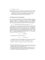
value should be on the order of 5.5 to 6.5, as shown in Figure 7.1.
Using a factor of safety of three, the allowable soil bearing pressure q
a
for
footings on clay would be
For
f
= 0 or very small, the unconfined compressive strength is twice the
cohesion value of clay. Thus,
q
cN
a
c
=
3
a
Nq
q
a
cu
u
=
=
6
©2000 CRC Press LLC
where
q
u
is the unconfined compressive strength. For most structures the consultants
are dealing with, it will be sufficient to assume that the allowable soil-bearing
pressure for footing on clay is equal to the unconfined compressive strength. In using
the unconfined compressive strength values for footing designs, the following should
be considered:
Average value
— It is a mistake to determine the value by averaging all the
data obtained from the laboratory. Experience should guide the consultant
in selecting the most reliable and applicable ones.
Water table
— The vicinity of the water table or the likelihood of the
development of a perched water condition should be of prime importance
in selecting the design value. Most foundation failures take place, not due
to underdesign, but due to the failure to recognize the possibility of the
saturation of the footing soils.
Drainage
— It is common practice to provide drains along the footings with
the intention of keeping the foundation dry. Such drains may not have an
adequate outlet, or sometimes the outlet has been blocked. As a result, the
soils beneath the footing can be completely saturated for years without
detection.
Soft layer
— The presence of a soft layer sandwiched between relatively
firm clays should not be ignored. During exploratory drilling, such a layer
can be overlooked by the field engineer. If such condition is suspected,
the bearing capacity should be reduced.
FIGURE 7.1
Bearing capacity factors for foundation on clay (after Skempton).
©2000 CRC Press LLC
7.1.1 S
HAPE
OF
F
OOTINGS
The above analysis is based on Terzaghi’s theory of continuous footings, a condition
that rarely exists in practice. A great deal of research has been conducted on the
effects of footing shape and bearing capacity. The ratio between breadth and length
affects the bearing capacity factor N
c
as shown in Figure 7.1.
In general, for a square or a circular footing, the calculated bearing capacity for
continuous footings can be increased by 20%, that is, multiplying by a factor
(1+0.2 B/L). In practice, the consultants will find that assigning a conservative
bearing capacity to the design does not substantially increase the construction cost.
For small or medium-sized structures, it is often not worthwhile to argue about
bearing capacity plus or minus on the order of 500 psf
Bear in mind that the controlling factor for the design of footings on clay is the
unconfined compressive strength value. In case of a questionable site, the field
engineer should be instructed to take continuous penetration tests and samplings, so
that any soft layer or any erroneous condition will not be overlooked.
7.2 STABILITY OF FOUNDATION
The stability of a structure founded on clay is controlled by the safety against shear
failure and with tolerable settlement. Since only in rare cases does foundation shear
failure take place, the design criteria is generally governed by settlement consider-
ations. To estimate the amount of settlement, it is necessary to study the loaded
depth of the footings and the consolidation characteristics of the clay.
7.2.1 L
OADED
D
EPTH
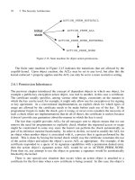
The classical pressure bulb theory based on Boussinesq’s equation can be used. The
shapes of the pressure bulb for continuous, circular, and square footings are shown
in Figure 7.2.
Examination of the stress distribution within the pressure bulb indicates the
following:
The most commonly used pressure bulb is the one for 0.2 q since in practical
cases any stress less than 0.2 q is often of little consequence. Therefore, for all
TABLE 7.1
Stress Distribution Within the Pressure Bulb
Depth Below
Footing Width B
Percentage of Uniform
Pressure for Square Footing
Percentage of Uniform Pressure
for Continuous Footing
0.5 B 70% 80%
1.0 B 35% 55%
1.5 B 18% 40%
2.0 B 12% 28%
©2000 CRC Press LLC
practical purposes, the pressure bulb for a square footing can be considered as 1.5 B
wide and 1.5 B deep, B being the width of the footing.
7.2.2 C
ONSOLIDATION
C
HARACTERISTICS
Typical consolidation characteristics of clay are given in Chapter 6 under
Consolidation Test
. Referring again to the consolidation test result as indicated in
Figure 6.2, the amount of settlement can be estimated as follows:
1. For a footing width of 30 in., the depth of the pressure bulb according to
the theoretical approach is 2.5 times the footing width. Since the effective
pressure is only about 80% of the actual pressure, and the effective depth
of the pressure bulb is less than the theoretical amount, it is assumed that
actual effective depth is only on the order of 1.5 times the footing width.
2. Based on the above assumption, the amount of settlement for a 30-in
wide footing under a pressure of 3000 pounds per square foot in a saturated
condition is (30)(1.5)(7.5%) = 3.4 in.
FIGURE 7.2
Vertical stresses under footings: (a) under a continuous footing; (b) under a
circular footing; (c) under a square footing.
©2000 CRC Press LLC
3. With the in situ condition, the soil settles 2.5% under a pressure of
1000 psf. It is estimated that under a pressure of 3000 psf the sample will
settle only 7.5 to 2.5%. The footing settlement will be (30)(1.5)(5.0%) =
2.3 inches.
4. On the above basis, it is estimated that the actual amount of settlement
of the structure as reflected by the consolidation test should be 25 to 50%
of the calculated figure, that is, 0.8 to 1.7 in. in a saturated state and 0.6 to
1.2 in. in the in situ state.
The above estimate is of course very rough. No consideration has been given
to such factors as the sample thickness, the uniformity of the soil, duration of the
test, and many other factors.
For years, the academicians were interested in the study of settlement prediction.
It is well recognized that if the subsoil consists of normally loaded clay, the subsoil
is homogeneous, and the water table is stable, then the total settlement can be
predicted with a reasonable degree of reliability. Unfortunately, such conditions
seldom exist in the real world.
Geotechnical consultants are more interested in differential settlement, and if the
predicted settlement comes within 100% of the actual value, they are considered to
have done an excellent job. Consultants do not spend time studying a single sample;
instead, they would rather perform tests on as many samples as they can afford. In this
manner, they will have a better grasp of the amount of differential settlement to be
expected. An experienced geotechnical consultant hesitates to put any predicted settle-
ment value in the report unless required to do so and only with many qualifications.
For geotechnical consultants dealing with recommendations for most structures
founded on clay, the following steps are suggested:
1. Assign soil bearing pressure based on penetration resistance and uncon-
fined compressive strength tests for the ultimate value. Select the logical
values instead of using the maximum or the minimum values.
2. Check the amount of maximum settlement by consolidation test.
3. Review the assigned value by checking with existing data.
7.3 FOOTINGS ON SOFT OR EXPANSIVE CLAYS
This chapter deals essentially with shallow foundations founded on clay. The struc-
tures most geotechnical consultants encounter are small- or medium-sized buildings
such as schools, medium-height apartments, warehouses, etc., where elaborate stud-
ies are not required or cannot be afforded. Oddly, these are projects that give the
consultants the most problems. Lawsuits generated by these owners can often ruin
one’s business.
At the same time, where sufficient funding is reserved for detailed study, larger
projects are highly competitive and seldom acquired. Interestingly, most of the
hundreds of papers published in technical journals discuss problems seldom encoun-
tered. Soil engineering deeply involved with geology, hydrology, or structures will
not be included in this book.
©2000 CRC Press LLC
7.3.1 R
AFT
F
OUNDATION
A raft foundation is a combined footing that covers the entire area beneath a structure
and supports all the walls and columns. A raft foundation is used when the allowable
soil pressure is so small that the use of an individual footing will not be economical.
A typical example of such a case is the San Francisco area, where the bay mud is
soft and the firm bearing stratum deep.
Since the area occupied by the raft is limited by the area occupied by the building,
it is difficult to change the soil pressure by adjusting the size of the raft. The design
of a raft foundation should be a joint effort between the structural engineer and the
geotechnical engineer. Since the loaded depth of a raft does not control settlement,
the depth at which the raft is located is sometimes made so great that the weight of
the structure is compensated for the weight of the excavated soil.
If very soft clay is encountered and it is necessary to place the footings on such
clay, careful analysis of the shear strength of the clay is necessary. The use of a
vane shear test correctly interpreted presents the most reliable results. The triaxial
shear test is time-consuming and its results depend a great deal on the selected
procedure. An experienced operator is necessary to render accurate results. The direct
shear test is simple, requiring less operation skill. Unit cohesion obtained from the
direct shear test is sometimes more reliable than the unconfined compression test.
7.3.2 F
OOTINGS
ON
E
XPANSIVE
S
OILS
The design of footings on expansive soils did not receive attention until recent years.
This is probably because much of the expansive soil is located in arid, underdevel-
oped areas.
Contrary to settlement, expansive soils heave upon wetting. The design criteria
for footings on expansive clay is not focused on the allowable bearing pressure but
on the swelling pressure. The swelling pressure of expansive soils can exceed 15 tons
per square foot. For footing design, the following basic factors should enter into
consideration:
1. Sufficient dead load pressure should be exerted on the footings to balance
the swelling pressure.
2. The structure should be rigid enough so that differential heaving can be
tolerated.
3. The swelling potential of the foundation soils can be eliminated or
reduced.
7.3.3 C
ONTINUOUS
F
OOTINGS
Instead of using wide footings to distribute the foundation load, footings on expansive
clays should be as narrow as possible. The use of such construction should be limited
to clays with a swelling potential of less than 1% and a swelling pressure of less than
3000 pounds per square foot. The limiting footing width is the width of the foundation
wall. Continuous footings are widely used in China, Israel, Africa, and other parts of
the world where the subsoil consists of illite instead of montmorillonite.
©2000 CRC Press LLC
7.3.4 P
AD
F
OUNDATION
The pad foundation system consists essentially of a series of individual footing pads
placed on the upper soils and spanned by grade beams. The system allows the
concentration of the dead load. Thus, the swelling pressure can be balanced. The
use of a pad foundation system can be advantageous where the bedrock or bearing
stratum is deep and cannot be reached economically with a deep foundation system.
It is theoretically possible to exert any desirable dead load pressure on the soil
to prevent swelling. Actually, the capacity of the pad is limited by the allowable
bearing capacity of the upper soils. If the pads are placed on stiff swelling clays,
the maximum bearing capacity of the pad is limited by the unconfined compressive
strength of the clay.
If q
u
= 5000 psf, the practical dead load pressure that can be applied to the pad is
about 3000 psf (assuming the ratio of dead and live loads to be about one to three).
With this limitation, the individual pad foundation system can only be used in those
areas where the soils possess a medium degree of expansion with a volume change
on the order of 1 to 5% and a swelling pressure in the range of 3000 to 5000 psf.
7.3.5 M
AT
F
OUNDATION
Mat foundation is actually a type of raft foundation. Instead of distributing the
structural load, it distributes the swelling pressure. The mat should be designed to
receive both the positive and the negative moments. Positive moment includes those
induced by both the dead and the live load pressures exerted on the mat. Negative
moment consists mainly of that pressure caused by the swelling of the under-mat
soils. There would be tilting of the mat, but the performance of the building would
not be structurally affected. The limitations of such a system are:
1. The system thus far is limited to moderately swelling soils.
2. The configuration of the structure must be relatively simple.
3. The load exerted on the foundation must be light.
4. Single-level construction is required. It would be difficult to apply such
construction to buildings with basements.
Mat foundation systems have been widely used in southern Texas, where mod-
erate swelling soils are encountered. The design of a mat foundation should be in
the hands of both structural and geotechnical engineers.
REFERENCES
F.H. Chen,
Foundations on Expansive Soils,
Elsevier Science, New York, 1988.
R. Peck, W. Hanson, and T.H. Thornburn,
Foundation Engineering,
John Wiley & Sons, 1953.
A. W. Skempton, The Bearing Capacity of Clays, Proc, British Bldg. Research Congress, 1,
1951.
K. Terzaghi and R. Peck,
Soil Mechanics in Engineering Practice,
John Wiley & Sons, 1945.
K. Terzaghi, R. Peck, and G. Mesri,
Soil Mechanics in Engineering Practice,
John Wiley-
Interscience Publication, John Wiley & Sons, 1996.
0-8493-????-?/97/$0.00+$.50
© 1997 by CRC Press LLC
8
©2000 CRC Press LLC
Footings on Sand
CONTENTS
8.1 Allowable Bearing Capacity
8.1.1 Shear Failure
8.1.2 Relative Density
8.1.3 Penetration Resistance
8.1.4 Gradation
8.1.5 Meyerhof’s Analysis
8.2 Settlement of Footings
8.2.1 Footing Size and Settlement
8.2.2 Footing Depth and Settlement
8.2.3 Penetration Resistance and Settlement
8.2.4 Water Table and Settlement
8.3 Rational Design of Footing Foundation on Sand
8.3.1 Typical Design Example
References
The principle of the design of footings on sands is essentially the same as the design
of footing on clays. In soil mechanics, the definition of sand refers to cohesionless
soils with little or no fines. This includes gravely sands, silty sands, clean sands,
fairly clean sands, and gravel.
Engineers as well as the public generally have the conception that sandy soils
are good bearing soils and will not pose much of a foundation problem. In fact, in
Riyadh, Saudi Arabia, during the oil boom period, most structures were erected on
sandy soils without the benefit of soil investigations.
In fact, distress experienced on structures founded on sand is not uncommon,
especially for subsoils containing large amounts of cobbles. Excessive settlement or
sometimes even shear failure can take place when there is a sudden change of the
water table elevation.
8.1 ALLOWABLE BEARING CAPACITY
The criteria for designing a safe foundation on sand are the same as those for footings
on clay. That is, the possibility of footings breaking in the ground generally refers
to “shear failure” or “punching shear,” and settlement produced by the load should
be within a tolerable limit.
For structures founded on sandy soils, the settlement can take place almost imme-
diately. The settlement criteria generally determine the allowable bearing capacity. Still,
the possibility of shear failure cannot be ignored. Geotechnical engineers often found
that punching shear took place at narrow footings and was ignored in the design.
©2000 CRC Press LLC
Sometimes it is difficult to determine whether the structure failed due to excessive
settlement or due to shear. For a consulting engineer dealing with medium or loose
sand, an ample factor of safety should be used. The design criteria should depend on
the results obtained from in situ testing rather than from theoretical analysis.
8.1.1 S
HEAR
F
AILURE
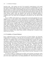
The concept of shear failure of footing on sands (Figure 8.1) was established first
by Prandtl and later extended by Terzaghi, Meyernof, Buisman, Casqot, De Beer,
and many others.
The general approaches of all studies are similar. They usually follow the basic
assumption that the soil is homogenous, from the surface to a depth that is at least
twice the width of the footings.
As explained by Peck, the wedge a’o’d cannot penetrate the soil because of the
roughness of the base. It moves down as a unit. As it moves, it displaces the adjacent
material. Consequently, the sand is subjected to severe shearing distortion and slides
outward and upward along the boundary’s o’bd. The movement is resisted by the
shearing strength of the sand along o’bd and the weight of the sand in the sliding masses.
The mechanics involving the ultimate bearing capacity under such a condition
is very complex. It involves the passive pressure exerted by the adjacent soils, further
complicated by the drained and undrained conditions. The result in which the
consultants are interested is that the ultimate bearing capacity may be expressed as
and the net ultimate bearing capacity as
where
N
g
N
q
are bearing capacity factors, their values can be evaluated by Figure 8.2.
FIGURE 8.1
Cross-section through long footing on sand (left side, after Peck).
qd B N + D N
f
q
¢
-
1
2
ggg
qd qd D
BN D N
f
f
q
=
¢
-
=+ -
()
g
g
gg
1
2
1.
©2000 CRC Press LLC
8.1.2 R
ELATIVE
D
ENSITY
The relative density of sand is defined by the equation:
in which
e
o
= void ratio of sand in its loosest state
e
min
= void ratio of sand in its densest state, which can be obtained in the
laboratory
e
= void ratio of sand in the field
Relative density can be determined when the maximum, the minimum, and the
actual field density of the sand are known. The more uniform the sand (SP), the
nearer its e
o
and e
min
will approach the values of equal spheres. For well-graded
sands (SW), both e
o
and e
min
values are small and as a result a higher relative density
value is expected.
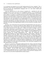
FIGURE 8.2
Relation between bearing capacity factors and angle of internal friction and
penetration resistance (after Peck).
Dr
ee
ee
o
o
=
-
()
-
()
min
©2000 CRC Press LLC
8.1.3 P
ENETRATION
R
ESISTANCE
The accuracy in the determination of the in situ
angle of internal friction for granular
soils depends on the quality of the undisturbed samples. The procedures involve an
experienced operator, costly equipment, and time-consuming activities. For soil
containing a large percentage of gravel and cobble, laboratory testing depends on
the use of a large-diameter triaxial cylinder. For small projects, such elaborate
sampling and testing are often not justified.
The simplest and least expensive procedure is to correlate internal friction value
with standard penetration test results, as shown in Figure 8.2. The standard penetra-
tion test result can often be deceiving, as discussed in Chapter 3. Data obtained from
the penetration resistance test, when carefully employed, still presents the most
convenient and inexpensive method for determining the bearing capacity of granular
soils.
Geotechnical consultants depend on the field penetration resistance value to
assign the bearing capacity of footings on sand. Figure 8.3 is based on depth of
surcharge D = 3 and a factor of safety of two. The choice of the factor of safety is
discussed under a separate heading.
For most projects, the width of the footing is less than 5 ft. The beginnings of
the curves actually control most construction.
8.1.4 G
RADATION
The gradation of granular soils directly affects their relative density, and hence their
bearing capacity. When gravely soils are encountered, their bearing value as well as
their amount of settlement can be different from sands with the same angle of internal
friction. Both the maximum and the minimum densities increase with the higher
percentage of gravel, up to probably as much as 60%. The presence of cobbles also
greatly affects the bearing capacity. The larger the size of the aggregate, the higher
the maximum and the minimum densities.
If the soil contains more than 50% of gravel with a maximum size exceeding
2 in., the values of the bearing capacity assigned for sands as indicated by the
previous curves are usually very conservative.
Gradation analysis should be performed for every granular soil. Care should be
taken that the sample represents the average site subsoil. With the information
furnished from the gradation analysis, it is possible to have a better correlation
between the penetration resistance and the bearing capacity.
8.1.5 M
EYERHOF
’
S
A
NALYSIS
Bearing capacity analysis made by G.G. Meyerhof assumed that the shear zone
extends above the foundation level. Consequently, he assigned a much higher bearing
value than that of Terzaghi. Meyerhof estimated the relationship between density,
penetration resistance, and angle of internal friction of cohesionless soil as in
Table 8.1.
©2000 CRC Press LLC
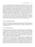
FIGURE 8.3
Width of footing versus bearing capacity for various penetration resistance
value.
©2000 CRC Press LLC
Using the above relationship, the ultimate bearing capacity can be expressed as
follows:
where
D
is the depth of the surcharge,
B
is the width of the footings, and
N
is the
penetration resistance in blows per foot.
From Figure 8.4, Meyerhof’s values are considerably higher, even with the use
of a factor of safety of three. It appears that his solution is nearer to the observed
actual load test results.
In Terzaghi’s analysis, footings with a width less than 10 ft and founded on
sands with a penetration resistance less than ten blows per foot, there is the risk of
shear failure. In Meyerhof’s solution, even with a very narrow footing founded on
low blow count sands, shear failure will not take place.
It is believed that Meyerhof’s solution is more realistic and should be used at
least for the upper limit in the bearing capacity determination. In sands containing
more than 50% gravel and cobble, Meyerhof’s solution can be applied with confi-
dence. However, for fine uniform sand, Meyerhof’s values should be used with care.
8.2 SETTLEMENT OF FOOTINGS
The stress and strain relationships of sand cannot be approximated by a straight line.
Hence, the term modulus of elasticity of the sand mass cannot be applied. An elastic
theorem cannot be used for estimating the amount of settlement for footings on sand
under a static load. The factors affecting the settlement of footings on sand are as
follows:
1.
Relative Density
— The rigidity of a sand mass increases sharply with
the increase of its relative density
2. The shape and size of the sand grain
TABLE 8.1
Relationship Between Density, Penetration Resistance,
and Angle of Internal Friction
State of
Packing
Relative
Density
Standard Penetration
Resistance (blow/foot)
Angle of Internal
Friction (degree)
Very loose 0.2 4 30
Loose 0.2–0.4 4–10 30–35
Compact 0.4–0.6 10–30 35–40
Dense 0.6–0.8 30–50 40–45
Very dense 0.8 50 45
qNB
D
B
d
=+
()
È
Î
Í
ù
û
ú
1 200
©2000 CRC Press LLC
3.
Unit Weight
— Unit dry weight directly reflects the degree of compact-
ness of the sand mass
4.
Water Table
— Since the submerged unit weight of sand is only about
half that of moist or dry sand, the water table plays an important role in
settlement.
FIGURE 8.4
Width of footing versus bearing capacity for various penetration resistance
values, as used by Meyerhof.
©2000 CRC Press LLC
8.2.1 F
OOTING
S
IZE
AND
S
ETTLEMENT
Terzaghi has shown that about 80% of the total settlement is due to the consolidation
of the soil mass within the pressure bulb, bounded by the line representing a vertical
pressure of one fifth of the applied load intensity. By similarity, it is apparent that the
settlement should be proportional to the width (Figure 8.5). However, as soils cannot
be considered as homogeneous material, especially for the cohesionless soil, the effect
of size on settlement cannot be determined from the theoretical considerations.
Peck stated in 1996 that at a given load per unit of area of a base of a footing,
the depth of the body of sand subject to intense compression and deformations
increases as the width of the footing increases. On the other hand, at very small
widths, the ultimate bearing capacity of a loaded area is very small; consequently
at very small widths, even at low soil pressures, the loaded area may sink into the
ground as shown in Figure 8.5. This is one basis for commonly requiring the test
plate in a load test be at least 4 ft
2
.
8.2.2 F
OOTING
D
EPTH
AND
S
ETTLEMENT
For footings of a given size, the greater the depth below the original grade, the
greater may be the allowable bearing pressure for a given settlement. It is not the
depth that directly affects the results; the important factor is the ratio of the depth
to the width (D/B), which is termed the depth factor. It was shown that for a depth
equal to one half the width of the footings, the amount of settlement is only half of
that in the surface loading condition.
Adjustment of the depth effect on the allowable bearing pressure on sand is
seldom attempted. However, it is a general practice for geotechnical engineers to
assign a higher bearing pressure for piers bottomed on sand than spread footings
founded on the same material.
It must be emphasized that the depth effect is based on undisturbed, homogenous
sands; disturbance to the soil during construction may affect the depth effect. Terzaghi
FIGURE 8.5
Relation between the width of square footing and settlement under same load
per unit area (after Peck).
©2000 CRC Press LLC
has called attention to the fact that the loosening of soil during the excavation of a
deep shaft in sand may lead to settlements that are as large as those which would
occur under the same loading at ground surface.
8.2.3 P
ENETRATION
R
ESISTANCE
AND
S
ETTLEMENT
The simplest and easiest method in evaluating the bearing capacity of footings
founded on granular soils is by correlating with the penetration resistance value
(Figure 8.6). The standard penetration test, when performed on medium-grain gravel
and sand, is reliable and easy to perform. As early as 1948, Terzaghi and Peck
proposed the correlation of bearing capacity and penetration resistance with the
following equation:
where
q
d
= The allowable bearing capacity in pounds per square foot
N
= Penetration resistance in blows per foot
FIGURE 8.6
Penetration resistance and allowable pressure.
q
N
d
=¥
8
2000
©2000 CRC Press LLC
The above equation is based on the following assumptions:
1. Allowable pressure is based on a footing settlement of 1 in.
2. The water table is at a depth of at least a distance equal to the width of
the footing.
3. The equation established on the basis that the width of the footing is less
than four feet, which is the size of footings most commonly used.
4. The footings are placed on the surface of the sand with no consideration
of the depth effect.
5. The soil consists of sands with little or no gravel.
Meyerhof in 1965 stated that by using Peck’s figure, the estimated settlements
vary from approximately 1.5 to 3 times the observed value.
In a recent publication, Peck changed the bearing capacity versus penetration
resistance equation by
N
/5 instead of
N
/8. Still, the consultants found that the
relationship is conservative. For sands with some gravel and for the usual footing
depth, about 3 ft below ground surface, the allowable soil pressure can be greatly
increased. At an upper limit, the equation can be modified as:
The above relationship is plotted as shown in Figure 8.6. In choosing the proper
allowable pressure, geotechnical consultants should rely on their judgment more
than charts and figures. The following should enter into consideration:
1. The percentage of gravel and cobbles in the deposit
2. The depth and width ratios of the footing
3. The amount of silt and clay in the deposit
4. The possibility of rise of the water table
5. The possibility of the development of a perched water condition
If all conditions are not favorable, use Peck’s value. These conditions include
the following: if the material does not contain a large amount of gravel; if the footings
are placed near ground surface; and if the water table is near the base of the footings.
On the other hand, if all conditions are favorable, and if neighboring structures have
not suffered damage, then there is no reason why the upper limit as shown in
Figure 8.6 cannot be economically used.
Using the above relationship, a convenient chart can be made for estimating the
allowable soil pressure for various sizes of footings based on the penetration resis-
tance data as shown in Figure 8.7. A similar chart can be prepared for the upper
limit used by Peck. It is assumed that the footing width between 1 and 3 ft has the
same allowable pressure. The chart is not applicable for a footing width of less than
1 ft.
q
N
d
=
Ê
Ë
ˆ
¯
¥
5
2000 psf
©2000 CRC Press LLC
8.2.4 W
ATER
T
ABLE
AND
S
ETTLEMENT
The position of the water table plays an important role in the determination of the
stability of foundations on sandy soils. The water table elevation affects both the
bearing capacity and the settlement of the foundation.
FIGURE 8.7
Relationship between
N
value and allowable pressure for maximum settlement
of 1 in.
©2000 CRC Press LLC
On the issue of correction for the water table, Peck commented in 1996 as
follows: If the water table lies above the loaded depth of the footing, the confining
pressure of the sand is reduced. Hence, the settlement correspondingly increases as
compared to the values if the water tables were below the loaded depth. However,
the reductions in confining pressure also cause the reduction in the standard pene-
tration resistance value. The two effects largely compensate for each other. Therefore,
the presence of a high water table can appropriately be ignored, and no water table
correction is needed.
On the other hand, if the water tables were to rise into or above the loaded depth
after the penetration tests were conducted, the actual settlement can be totally
different. The confining pressure of sand beneath the footings and beside the footings
is proportional to the unit weight of the sands. Hence if the sand mass has changed
from the dry or moist state to a submerged state, the settlement of the footings is
likely to be increased by as much as twice the amount.
It is important that the geotechnical engineer check the possibility of shear failure
on narrow footings founded on loose sand, with the water table located near the
footing level. Another aspect is the possibility that with the high water table condi-
tion, the ultimate bearing capacity of granular soils may be reduced by liquefaction
due to shock or vibration. (Earthquake consideration is not within the realm of this
book.)
The water table may not pose a problem at the time of investigation. But it is
possible that due to local condition changes, the water table will rise or drop to such
an amount that the stability of the structure will be endangered. A thorough inves-
tigation of the site is essential to determine such a possibility.
Throughout the site of a large structure, the depth of the water table may not be
uniform. This is especially true when irrigation ditches or other water-carrying
structures are located in the vicinity of the structures. Part of the footings in the
structure can be affected by the high water condition while others can be free from
the effects of water. Differential settlement of the footings is important and must be
carefully studied.
8.3 RATIONAL DESIGN OF FOOTING FOUNDATION
ON SAND
As discussed above, the stability of footing foundations on sand depends on many
factors. Both from the standpoint of shear and settlement, these factors cannot be
determined with certainty. Since almost all soils existing in nature are not homog-
enous, at a building site the soils vary in both vertical and horizontal directions.
Only in rare cases can the theoretical analysis apply. The following details should
be considered.
1. The basis of most theoretical analyses hinges on the value of the in situ
penetration test value. Extensive research has been done in the past years
to refine, correct, and correlate the field data. A field engineer admits that
©2000 CRC Press LLC
the blow count data obtained greatly depends on the skill of the operator,
the condition of the sampler, and the depth from which the tests are taken.
Penetration resistance data cannot be treated as a mathematical function
and applied to an equation as in treatment of steel or plastic. This is more
evident when the blow count is below 4 or above 50.
2. A field engineer realizes that the penetration resistance value obtained
can be totally different within a short distance of 10 ft at the same depth.
For a given project, the number of borings and the frequency of the
penetration tests taken are limited and the
N
value obtained at best can
only give a general idea of the average subsoil condition.
3. The most important factor to be considered by the geotechnical engineers
is the water table level. The groundwater level is important not only at
the time of investigation but also in the future. Fortunately, the perched
water conditions seldom exist in the granular soils.
4. Clean Sand (SW-SP) seldom exists. Most granular soils contain apprecia-
ble amounts of fines. A percentage of silt and clay, as much as 15%, is
commonly encountered. In such cases, the settlement of the subsoil should
be controlled by a consolidation test. Settlement estimates on silty sands
should be treated in the same manner as the consolidation of clays.
5. Homogenous sand strata extending to a great depth seldom exist in nature.
Pockets and layers of soft silt or clay can sometimes be present within
the loaded depth of the footings. Such layers can easily be missed by the
driller or noticed by the field engineer. Consolidation of such strata may
control the settlement of the structure, and calculations of the settlement
of sands become a minor item.
6. When a soft layer of clay is located below the sand strata, settlement of
such a layer can control the behavior of the structure. Compressible clay
layers may be located at a considerable distance below the footings.
8.3.1 T
YPICAL
D
ESIGN
E
XAMPLE
From the detailed analysis of the design criteria to be considered in the design of
foundation on sand, it is up to the geotechnical engineer to choose a rational and
economical recommendation for the project. This can best be illustrated by the
following typical case.
Project: A single-story warehouse structure with
a full live load.
Column load: Varies from 50 to 200 kips.
Footing Depth: 3 ft below ground (below frost depth).
Field data: Average penetration resistance
N
= 10
(within loaded depth).
Factor of safety: Between two and three.
Allowable Maximum Settlement: 1 in. (differential settlement .75 in.).
©2000 CRC Press LLC
From the previous discussions, namely:
Penetration resistance and allowable pressure (upper and lower limit).
(Figure 8.6)
Width of footing versus bearing capacity (Meyerhof). (Figure 8.4)
Width of footing versus penetration resistance. (Figure 8.3)
Penetration resistance and allowable pressure (lower limit). (Figure 8.7)
By using
N
= 10 value, the relationship between width of footing versus allow-
able pressure can be established by using Figures 8.8 and 8.9. Also, for settlement
consideration the relationship between width of footing and bearing capacity can be
established by using Figures 8.6 and 8.7. This is shown in Figures 8.8 and 8.9.
In the upper limit with a footing width less than 2.5 ft and in the lower limit
with a footing width less than 4.5 ft, the design is controlled by the shear consider-
ation. The choice of the use of the upper or the lower limit for the final recommen-
dation depends on the content of fines in the deposit, the water table condition, and
the uniformity of the deposit. These are discussed as follows:
1. If the subsoil contains more than 15% of gravel and cobble and if the
water table is located below the loaded depth of the footings with no
possibility of rising, then the upper limits can be used with confi-
dence.With a column load of 150 kips, the size of the footing should be
on the order of 7
¥
7 ft.
2. If the subsoil contains essentially sand with no appreciable amount of
gravel and cobbles, and there is the possibility that the water table may
rise to within the loaded depth of the footing, then the lower limit should
be used. That is, the size of the footing should be on the order of 9
¥
9 ft.
3. If other conditions are the same as above, but there is the possibility that
the water table may rise to near the ground surface, then the footing size
given above should be increased by as much as 50%. As an alternative,
a reliable permanent dewatering system or drainage system can be
installed to lower the water table. In such a case, the size of the footings
can be reduced.
Irrespective of all the research and study done on the stability of the footing
foundation on sand, the geotechnical engineer should use his or her past experience,
keen observations, and common sense to achieve a logical and safe foundation
system.
©2000 CRC Press LLC
FIGURE 8.8
Width of footing versus allowable pressure. Upper and lower design limit for
N
= 10.