Autonomous Robotic Systems - Anibal T. de Almeida and Oussama Khatib (Eds) Part 10 pot
Bạn đang xem bản rút gọn của tài liệu. Xem và tải ngay bản đầy đủ của tài liệu tại đây (1.35 MB, 20 trang )
17'5
Gdzzly
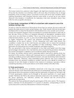
Figure 10. Results from field trip. The diagram in the top left hand corner
shows the experimental setup. Note that this setup caused range shadows
behind large rocks.
176
Figure 11. The view from above (top), and from the front (bottom) of the
grizzly covered in large rocks.
177
Figure 12. Results from the laser scanner looking at a charging face. Note the
enlargement of the front view clearly shows a ring of drilled holes and a butt.
t78
ideal location of the laser scanner would have been directly above the grizzly,
eliminating most shadows, but this was not possible given the limited amount
of time on site. Figure 11 shows in more detail the data collected when some
large rocks were dumped on the grizzly. The lower portion of the figure shows
the scene from the front.
Figure 12 shows some different views of the end of a mine tunnel, all
derived from one scan. The figure clearly shows details such as the drilled blast
holes and a blasting 'butt' (basically a hole in the rock face caused from the
previous blasting cycle). The floor appears extremely smooth because it was a
pool of water.
3.2. A seml-automated rock breaker
Dealing with oversize rocks is a common problem in surface and underground
mining. Large rocks may jam a crushing plant or chute, or be too large to
travel along a conveyor system. In underground mines grizzly screens are used
to filter out oversize rocks. A grizzly screen is typically a very solid steel
structure over an ore pass or crusher that provides a mesh size in the range
0.5 to lm. Material may reach the grizzly from an ore pass via a chain feeder
or be dumped directly by truck. The grizzly screens must be kept clear from
build up of loose material or oversize rocks. A rock-breaker, see Figure 6, is a
manually controlled hydraulic arm that carries a hydraulic impact hammer. In
structure it is akin to a back-hoe excavator, and kinematically it is similar to
a standard industrial robot.
In order to automate this process we would need
1. a computer controllable rock breaking boom,
2. a 3-D sensing system,
3. the automation system, and
4. a teleoperation system.
The proposed system would use 3-dimensional sensors to monitor the griz-
zly, and when necessary control the breaking boom so as to clear the griz-
zly. The imaging aspects of rock-breaker automation have been previously
studied[14, 15] and trialled in the laboratory using a small scale model [16].
Due to the difficulty, in what is a complex and only partially structured
environment, of foreseeing all eventualities 2 we do not believe that at this stage
it is feasible to fully automate the process. Complications involved in carrying
out this task include dealing with foreign objects such as timber props and
ground support bolts. In the event of the system being unable to autonomously
clear the grizzly, it would signal a remote operator who would use teleoperation
of the breaker to complete the task. Such limited human intervention would
be the most cost effective solution for dealing with these situations, and would
make it possible for a single operator to supervise several rock breakers located
at different sites around the mine.
2Rock shapes and type, and foreign objects.
179
.3-Dsensor
Computer controllable
rock break~
I ,, I
Grizzly
\
ii:: ration
Automation system
system
Figure 13. The proposed semi-automated rock breaker.
4. Conclusion
The ultimate aim of mine automation will be to remove miners from the haz-
ardous areas of the mining environment where the work will instead be per-
formed by autonomous and sensate mining machines. Such a vision is many
decades from reality and in the interim we can hope to make small steps to-
ward this goal. One step is to increase the productivity of existing mining
equipment by assisting the operator so that one operator can supervise several
machines. The dragline and the rock breaker automation projects described
here are example of this.
Considerable work within the robotics and computer vision is highly appli-
cable to real-world automation needs such as exist within the mining industry.
The research community has demonstrated the feasibility of using machine vi-
sion to 'close the loop' on the position of robot manipulators. Such technology
could be usefully applied to many applications in mining. Superficially these
may seem very different problems, but this is largely a matter of scale. Larger
machines in fact require reaction times that are considerably longer than those
being demonstrated now in robotics laboratories. The biggest, but not insur-
mountable, challenge is the complexity of scene analysis in a complex mining
environment.
Acknowledgements
The authors gratefully acknowledge the help of their colleagues Stuart Wolfe,
David Hainsworth, Stephen Nothdurft, Zheng-De Li, Jasmine Banks, Hal Gur-
genci, Don Flynn, Peter Nicolay, Allan Boughen and Daniel Sweatman. The
dragline project is funded by a consortium consisting of the Australian Coal
Association Research Programme (as project C5003), Pacific Coal Pty Ltd,
BHP Australia Coal Pty Ltd and the Cooperative Research Centre for Mining
Technology and Equipment (CMTE), a joint venture between AMIRA, CSIRO
180
and the University of Queensland. Bucyrus Erie Australia and Tritronics Pty.
Ltd. have provided valuable in-kind support, and Tarong Coal have gener-
ously allowed the automated swing system to be installed on their BE1370.
The underground mining robotics work has been supported by the CMTE and
AMIRA project P440 which was sponsored by Mount Isa Mines, Normandy
Poseidon and Western Mining.
References
[1] P. I. Corke, Visual Control of Robots: High-Performance visual servoing. Mecha-
tronics, Research Studies Press (John Wiley), 1996.
[2] S. Hutchinson, G. Hager, and P. Corke, "A tutorial on visual servo control,"
IEEE Transactions on Robotics and Automation, vol. 12, pp. 651-670, Oct.
1996.
[3] D. Hainsworth, G. Winstanley, Y. Li, P. Corke, and H. Gurgenci, "Automatic
control of dragline operation using machine vision control of bucket position,"
in Proc. First CMTE Annual Conference, (Brisbane), pp. 111-114, July 1994.
[4] P. I. Corke, G. Winstardey, and J. Roberts, "Dragfine modelling and control," in
Proe. IEEE Int. Conf. Robotics and Automation, (Albuquerque, NM), pp. 1657-
1662, 1997.
[5] G. Winstanley, P. Corke, and J. Roberts, "Dragfine swing automation," in Proc.
IEEE Int. Conf. Robotics and Automation, (Albuquerque, NM), pp. 1827-1832,
1997.
[6] Z. Li, P. Corke, and H. Gurgenci, "Modelling and simulation of an electro-
hydraulic mining manipulator," in Proc. IEEE Int. Conf. Robotics and Automa-
tion, (Albuquerque, NM), pp. 1663-1668, 1997.
[7] R. A. Jarvis, "A perspective on range finding techniques for computer vision,"
IEEE Transactions on Pattern Analysis and Machine Intelligence, vol. PAMI-5,
pp. 122-139, Mar. 1983.
[8] R. Chatila, S. Fleury, and M. Herrb, "Autonomous navigation in natural envi-
ronments," in Experimental Robotics III (T. Yoshikawa and F. Miyazaki, eds.),
pp. 425-443, Springer-Verlag, 1994.
[9] M. Thompson, ed., Manual of Photogrammetry. Falls Church, VA: American
Society of Photogrammetry, 3 ed., 1966.
[10] P. Fua~ "A parallel stereo algorithm that produces dense depth maps and pre-
serves image features," Machine Vision and Applications, vol. 6~ pp. 35-49~ 1993.
[11] R. Zabih and J. WoodfiU, "Non-parametric local transforms for computing visual
correspondence," in Proc. 3rd European Conf. Computer Vision, (Stockholm),
May 1994.
[12] P. Dunn and P. Corke, "Real-time stereopsis using FPGAs," in Proc. Intl. Work-
shop on Field Programmable Logic,, (Imperial College, London), Sept. 1997.
[13] J. Woodfill and B. V. Herzen, "Real-time stereo vision on the parts reconfig-
urable computer," in IEEE Workshop on FPGAs for Custom Computing Ma-
chines, pp. 242-250, Apr. 1997.
[14] S. Elgazzar, J. Domey, P. Boulanger, and G. Roth, "Three-dimensional imaging
for mining automation," in Proe. 5th Canadian Syrup. on Mining Automation,
pp. 334-340, 1992.
[15] J. Domey and M. Rioux, "3-d vision sensors and their potential applications
in mining automation," in 3rd Canadian Syrup. Mining Automation, (Montreal),
181
pp. 187-193, Sept. 1988.
[16] C. Cheung, W Ferrie, R. Dimitrakopoulos, and G. Carayanis, "Towards com-
puter vision driven rock modelling," in Proc. 2nd Canadian Conf. on Computer
Applications in the Mineral Industry, (Vancover~ B.C.), Sept. 1991.
HelpMate@, The Trackless Robotic Courier:
A Perspective on the Development of a
Commercial Autonomous Mobile Robot
John M. Evans
HelpMate Robotics, Inc.
Danbury, CT, USA
evans@helpmate, com
Bala Krishnamurthy
HelpMate Robotics, Inc.
Danbury, CT, USA
Abstract
HelpMate Robotics has developed an autonomous mobile robot courier for material
transport in hospitals. These machines are in operation around the world,
operating in uncontrolled and unsupervised environments up to 24 hours per day.
The history and technology of the HelpMate robot are presented in this paper with
the intention of providing a real world perspective on transitionmg technology from
the laboratory to the marketplace.
1 Introduction
HelpMate Robotics Inc. (HRI), of Danbury, Connecticut, USA, has developed a
hospital courier robot that is the benchmark of commercial success in the emerging
field of service robots. This paper will explore the decade of development of the
HelpMate robot, focusing on the evolution of the technology from laboratory
exploration to hardened commercial product.
In trying to define market opportunities for robots in service applications and to
match enabling technologies against those opportunities, several possibilities
originally stood out: floor cleaning, security, hazardous enviromnents and hospital
materials transport. All required autonomous mobile robots navigating in indoor
structured environments. It was this technology base and these markets on which
we focused early attention.
1.1 The Hospital as a Target Market
Health care is an obvious market for automation because of the high and rising
costs that must be tamed if any attempt at universally available care is to be offered
in our society. Cost containment is an overriding theme in health care
183
management, and robotics is one technology to reduce labor costs. Operation of
hospitals around the clock on a multi-shift basis makes capital justification easier,
so this was a natural target.
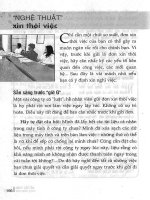
Development of the HelpMate concept has been described in earlier papers
[1,2,3,4,5]. The final machine, shown in Figure 1, is able to navigate in crowded
hallways, avoiding people and inanimate obstacles as it encounters them, and using
the walls of the hallways as the principal navigation reference. Figure 2 shows the
applications for HelpMate.
.~
~!i:~i+:i,i~iii i:i: .
!:~?NNiiiiii+~ii{i?iiii!iit ' iiiiiiiiiiiii~i~i~i~)~:
~i~iii~'iiliiii~'iiiii~}~'~i iiiiii~iiiii"!':iiiii"ii;i"'ii+iiii ~l
~.~.:':'.'¢~:::::~ ~::~':s:::-'; N:.:~ ::::::::::::::::::::::::
~i~.~:.+': ':-~:~::::~:.:~:: ::::::::-:.:: .:.~::::: •
+~l++i+++++++ '
x +~+::M :5-+~:- ++ +:+:+ +
I~~
++~+::.#++~+."+-'~.+'."."+:++!+ ~
[[~~+|+,+:+::+::::+++++i+ ~ :+++ :+!++:~+++++++++++++ii++++++++:.:i+.~+++
~~~i'~!+ i~i~ ,-~: :~:~!~iiii!~iii -::.::
========================== +l ".:~.::::::::::::::~i!! iiii "~i ".:-~!'ii:
~li' " ~+!":'+'~ ~i"+"!~!~i~i':~!~ii":+"i~ ::~ : :::::::::::::::::::::
~i + "========================================================================
:-: ~.+ :~ ~?:: :.:. ~::::::: <:~.~+-+~.:.:.~,. ~
"~:i ::+:+:+::.:.++ n, ~ , +,+ ?-1
Figure 1: HelpMate Robot Courier
184
Dietary: late and special request trays
Supply: equipment and material
Lab: speciman and sample transport
Pharmacy: medication and supplies
Med Records: patient files
Administration: mail and reports
Radiology: films
Mail: mail and packages
Figure 2: Applications of HelpMate
2 Navigation: a problem in Sensing
Over the years, we have come to believe that the key to autonomous mobile robot
navigation is sensory perception, ffyou can obtain a good, dynamic, high
resolution picture of the world around the robot, then you can successfully use any
of several algorithmic approaches to planning a collision free path through the
environment.
Much of the early work on navigation algorithms hypothesized known, static
worlds, what we would call "blocks worlds" after the highly structured and
artificial worlds used in early machine vision research [6]. The heritage is that of
trajectory planning for robot arms in free space, with force or compliance control
considered as a special case [7]. Work is still presented today on such ideas.
Potential field models, clothoids, path planning for non-holonomic vehicles: all
presume a totally known and static environment [8,9,10]
But the real world is not static. Hospital hallways, in particular, can be filled with
moving people: employees, patients and visitors. So the problem becomes one of
dynamic sensing, and control strategies must be dynamic and reactive.
Further, it turns out that there are many "stealth" objects in the real world for any
single sensory modality. Sound waves bounce off any hard, flat, angled surface and
are absorbed by soft material such as a blanket. Light bounces off mirrors and
chromed surfaces in a specular fashion and passes through glass, and light is
absorbed by flat black material such as black wool pants. Hence, a multiplicity of
different types of sensors maximizes the probability of sensing objects prior to
collision. Contact sensors to detect collision are always required.
The HelpMate robot uses sonar, vision, and contact sensors to interact safely with
people and obstacles in a hospital world. [3]
This combination of sensors is not unique and was in fact already known in the
research community before we started working on HelpMate. During the early and
185
mid-1980's there was a great deal of interest in autonomous mobile robots and
some very good work had been done before we started, going back to the 1960's.
[11,12,13,14]
In fact, after reviewing the literature and talking with some of the researchers at
leading universities, we felt when we started that developing commercial mobile
robots would be a straightforward matter of technology transfer of academic work
and then solving applications problems. Thirteen years later we are still trying to
tie up loose ends, but we finally have over one hundred machines nmning in the
real world, in uncontrolled environments, without supervision, 24 hours per day,
seven days per week, providing useful and cost effective transport services. It has
been anything but straightforward, as we will review in Section 4 below.
2.1 Sonar
Ultrasonic ranging is a basic modality for HelpMate. Some 28 different transducers
are located around the robot, looking for walls, for obstacles and for overhanging
objects. There are even transducers in the bumper looking straight down to see any
sudden drop off such as a stairway or the edge of a loading dock.
HelpMate uses the Polaroid electrostatic microphone transducers [ 15]. These
sensors were developed for focusing instant cameras. A foil microphone is used for
both transmitter and reciever. The microphone is driven by a 300 Volt train of
pulses, and a 150V bias is held to allow sensing of the return sound energy. We use
the Texas Instruments version of the asic drive chip to activate the transducers.
This provides a driving signal of 16 pulses at a single 49.4 KHz frequency. The
time of flight measurements begin with the start of the pulse train and end when
enough energy is returned to the microphone to exceed a trigger threshold. The
gain of the amplifier driving the trigger circuit is increased with time to
compensate for loss of signal strength for returns from more distant targets.
The main uncertainty in sonar measurement is direction of the return signal.
Researchers usually characterize the Polaroid field of view as 15 ° which is useful as
a general guideline. For example, the "Denning Ring" is the classic array for the
Polaroid sensors when used on robots with cylindrical geometry [16], with 24
sensors around the circumference of the robot, one every 15 °. However, the
microphones have a radiation pattern which is like a typical antenna pattern, the
15 ° being the 6dB width of the central lobe. Side lobes can be excited as far as 60 °
and more from normal. With the increasing gain in the detection circuit with time,
the chance of triggering on multi-path echos is significant.
Despite these measurement uncertainties, sonar and particularly the Polaroid
transducers have been a favorite choice of both researchers and entrepreneurs since
1980 for an obvious reason: price. Over two million dollars went into development
of the original sensor and drive circuitry and in volume it is now possible to procure
186
those sensors for less than $10 and less than $30 including the electronics. Nothing
else is competitive, so a large number of man years have gone into coping with the
problems of the Polaroid sensors [ 17,18,191. The same expenditure of effort might
have borne more fruit in developing alternatives I20,21,22]
After years of struggle we were able to effectively use the Polaroid sensors. The
HelpMate works, so we stay with those sensors.
2.2 Vision
Vision has been the main line of research for robotics and artificial intelligence
since the 1960's. Machine Vision has proven to be substantially more difficult than
anyone supposed it would be thirty years ago [23,24,25], but it is now both effective
and ubiquitous and, in the past several years, it is also become a low cost sensing
modality [26].
HelpMate must be very flexible in sensing its environment because obstacles will
cause it to deviate substantially from a planned route down the center of a hallway.
Vision seemed from the first to be an attractive modality because of the richness of
information and the structured geometry of the world in which the robot was to
operate.
Over the years, we have experimented with one and two dimensional images, with
views near the floor, normal and oblique views of the ceiling, optic flow of vertical
features, and structured light vision systems. Two concepts were deployed
originally with the first models of the HelpMate, one remains in the current design,
the structured light system [27].
Ceiling vision, which is no longer used, uses an image of the hallway ceiling lights
to extract information about tile relative orientation and position of the robot in its
environment [28]. The ceiling vision camera was pointed obliquely upward, giving
a long forward view of the ceiling, Ceiling lights and tiles were used to find the
center of the hallway and its alignment.
The structured light vision system is used for obstacle detection and avoidance [29].
A camera is pointed at a 45 degree angle toward the floor from near the top front of
the robot. Two light projectors send out planes of light parallel to the floor, one at
ankle height and one at knee height. The beams cut across the camera field of
view, giving a range for sensing obstacles of about two meters for the bottom strobe
and one meter for the top one.
The camera will see an empty field of view if there is nothing in front of the robot.
If there is an obstacle, tile planes of light will intersect with the obstacle, producing
a contour line of tile surface which the camera will see. Processing the camera
image, the distance from the bottom of the image to the first illuminated scan line
187
is a measure of distance to the obstacle, and the horizontal width of the contour line
indicates its size.
Optical filtering, electronic shuttering, and frame-to-flume differencing are used to
improve signal-to-noise and immunity to ambient lighting.
2.3 Contact Bumpers
For safely, the robot must be able to sense contact. There will always be some
obstacles in the environment that will defeat any finite array of non-contact
proximity sensors, so there must be a further line of defense.
HelpMate uses Tapeswitch
TM
sensors along the bumpers and vertically on corners.
These switches have an activation force of about six ounces, so they are very
sensitive to contact. The bumpers are mounted on elastomeric supports, so they
will move under a force of several pounds. Infrared proximity sensors detect
motion of the bumper and act as an additional and redundant collision detector.
2.4 Additional Sensory Modalities
The final sensory system that we added to the HelpMate was an absolute position
reference system. For long stretches of carpeted corridors there will be enough
wheel slippage that the robot can be off of its estimated position by tens of
centimeters. This is enough to cause problems in aligning with elevators or in
navigating through cluttered halls. To overcome this problem we have used
retroreflective tape affixed to the ceiling on the hanger bars for acoustic tiles, a
standard ceiling design. A pair of long range infrared proximity sensors are
mounted on the shoulders of the robot, pointed at the ceiling. These sensors see the
ceiling tape and provide information on both position and orientation at those
landmarkso
We have used this ceiling tape system for safety as well as for navigation
landmarks. At any point where there is an open stairwell or loading dock that
would create a hazardous environment for the robot, we place a wide section of
reflective tape on the ceiling, and this is used as by the robot as a warning. The
robot also has staircase detectors, so there is a "belt and suspenders" redundant
sensing approach for critical safety situations.
3 Navigation: A Problem in Control
With perfect odometry and in the absence of obstacles, navigation is reduced to
simple path following. In a real world environment, a combination of different
sensor modalities and control programs is needed to compensate for odometry
errors and to avoid obstacles.
188
3.10dometry
Odometry or dead reckoning (properly ded reckoning, from deduced reckoning, an
old Navy term describing the estimation of position of ships from velocity and time
and heading measurements) is the basis for almost all mobile robot systems.
Odometry or dead reckoning is used to refer to measurement of the robot's position
and heading from wheel encoder readings and other internal position and velocity
and acceleration sensors such as gyros or accelerometers or doppler velocity
sensors. A definitive survey is provided by Borenstein, Everett, and Feng. [30]
Odometry errors accumulate with time and depend upon the environmental
conditions. A rough or slippery or carpeted floor will produce greater errors than a
smooth tile floor, for example.
Navigation over a few meters, and potentially over tens of meters, is possible with
only odometry. At some point in any system, however, reference must be made to
outside landmarks to re-establish a position estimation that is correct with respect
to the external environment. This is the process of taking sensory data about the
external world and matching that to an internal map of the environment. We refer
to that process as localization. Position corrections are required both along the
direction of travel (Y direction) and perpendicular to the direction of travel (X
direction).
3.2 Localization
A prerequisite for acceptable robot navigation, in addition to adequate sensing, is
either detailed information about the environment or robust navigation algorithms
that compensate for the lack of
a priori
information. The HelpMate is provided
with some
a priori
information and endowed with enough intelligence to deal with
the inexact world model and to rationalize
the a priori
information with the
dynamic sensed model. The definition of 'some' and 'enough' has taken over 10
years to refine!
Once a world model is available, it is possible to use sensory data to match the
position of the robot to that model. This can be as simple as using single sensor
data for wall following [311, or as complex as matching a complete local map with
a global map [18,32]. Most work in the literature has matched features extracted
from the sensor data to corresponding elements of a global model [33, 34]. This is
the approach we use for HelpMate.
HelpMate navigates in what we would call a structured environment, with rigid and
unchanging geometric features of the building within the range of the sensors of the
robot. As such, the natural approach to localization is to use the sonar sensors to
measure the range to the walls of the hallways and to use the walls as the primary X
189
position reference. Exactly where the robot should travel with respect to those wall
is information in
the a priori
model, which we call the Topography.
Raw sonar sensor data, along with hallway wall information supplied via the
Topography, is used to estimate the X position and the heading. A line fitting
routine is used to extract a line segment from the list of sensor data representing the
wall. This is similar to the approach taken in the mid-80's by Crowley to match
line segments extracted from sonar data with those from a model [33]. The wall
registration module on the HelpMate runs every 150 ms and generates position and
heading corrections offwall segments.
Unless the hall is a particularly long one and is followed by' an area where the
positioning must immediately be exact or where the walls are often expected to be
obscured, the HelpMate needs no correction in the Y direction. This is because
once a turn is made into the next hall, any Y error in the previous hall is now
translated into an X error, and is usually corrected by the wall registration
algorithm within a few meters of travel.
Augmentation of natural landmarks is required in areas where the robot may be
required to travel long distances on carpeted areas, resulting in wheel slippage, and
then turn immediately into an elevator lobby area where precise positioning is
required. In cases such as these retroreflective tape is affixed on the ceiling just
before the end of the long hall. The tape is detected by the upward looking IR
sensors and the tape registration module, running every tick time, generates a
correction to both the Y position and the orientation of the robot.
3.3 Obstacle Avoidance
The primary responsibility of HelpMate is to operate safely, to avoid running into
anything, as it navigates down hallways. This requires a multiplicity of sensors, as
described in the previous section, and a way of combining and processing that
sensory data in a coherent way.
Combining data from multiple sensor modalifies is often called sensor fusion.
There are many teclmiques in use, including fuzzy logic [35], subsumption and
other state machine architectures [36] and various mapping schemes. HelpMate
uses a mapping approach that was derived from work at NIST by Albus and co-
workers[37], and work at CMU and Grenoble by Crowley [33] and Effes[17].
By the time HelpMate was started, the NIST work on hierarchical control had
evolved to the concept of interjecting an explicit world model hierarchy between a
sensor processing hierarchy and the control hierarchy. The idea was to use the
sensor data to servo the model and then to use the model data for control
calculations. We adopted this concept for HelpMate, using a Cartesian occupancy
grid representation similar to Elfes to combine data from sonar, from vision and
from contact bumpers, as shown in Figure 3.
190
Figure 3: Graphical Picture of Local Map as HelpMate Avoids an Obstacle
HelpMate's immediate environment is represented in Cartesian coordinates, unlike
Crowley's polar map[33] or that of Borenstein and Koren [38]. The local map is a
robo-centric occupancy grid representation with 35 X 35 cells, each representing a
128mm square, which works out to be approximately a 4.5 meter x 4.5 meter area
around the robot, but asymmetrically weighted with 2/3 of the cells ahead of the
robot and 1/3 behind
This local map is refreshed every 150 milliseconds with new weighted sonar,
vision, shield and contact bumper sensor information. The information pooled into
this local map is weighted dependent on the rate at which the data is gathered, the
reliability of the data and the importance of the data. Vision data, for example, is
given a higher weighting that sonar, because the data is less frequent and less prone
to error. The contact bumper data is mapped with an even higher certainty since it
is fleeting, was obviously something that escaped other sensor detection, and must
be retained in memory until the object is safely passed.
Dynamics are handled by overlaying a time based decay which slowly depletes the
memory of previously seen objects while retaining information long enough to get
around an obstacle that escapes detection by most of the sensors.
191
All obstacle detection is done using this composite local map. This map is scanned.
every 150 ms for available openings that lead to the final destination either directly
or by deviating around an obstacle. One opening is selected using path heuristics,
and position commands that direct the robot towards this opening are generated.
The commands to the drive module from the navigation module consist essentially
of forward and angular velocity every tick time. The 'set_velocity' and the 'jog'
command interface provided by the drive subsystem facilitates setting of the
velocity and the rate of turn in units of degrees per second, This interface is
basically that proposed by Crowley, although he adds position and acceleration in
each command and expects back an estimation of position uncertainty. We deal
with position uncertainty at a higher level as part of navigation.
HelpMate's path detection, selection and tracking calculation modules run every
150ms, and are based upon the configuration space approach where the robot is
represented as a point object and the obstacles are grown by the clearance required
to safely pass by [39]. A list of possible paths is generated by the path detection
module which restricts its search to file boundaries of the hallway, allowing for
position and orientation uncertainty. The openings detected are checked against
the size of the robot, including the clearance required for safe navigation. The right
and left edges of each opening are then represented as polygons large enough to
provide the specified obstacle avoidance distance. Paths are plotted to the closest
edges of these polygons, as graphically shown in Figure 3 above.
4 The Real World: Problems and Solutions
Betweeo the dream and the reality, as has been often noted, there can be quite a
gap. Real world applications are where substantial engineering problems can cause
budget and schedule overruns as theory and laboratory demonstration fail in
practice. The classic joke runs that the first 95% of the project is not so hard, it is
the second 95% that is difficult. In trying to develop a new product for a new
market, this is often the exact truth, since a product is not commercially viable until
it truly solves a customer need, reliably, at an affordable price, and the problems to
be overcome are unknown at the start of the project.
Between early 1988 and the end of 1990, some two and one-half years, we
struggled to move autonomous mobile robot technology, which performed well
enough in laboratory demonstrations, into the marketplace.
In January of 1991 we finally walked away from our first installation, in Danbury
Hospital in Danbury, Connecticut, and asked them to call us if they had problems.
In April we went to 24 hours per day and in June the robot was accepted and the
hospital began paying rent. Additional sites were operational by the end of 1991,
and in 1992 sites with multiple robots were operational. Since 1992 there have
192
been incremental improvements in reliability, in cost, and in functionality, but the
HelpMate was essentially operational at that point in time as a successful product.
This section will review some of the problems that were encountered and overcome
in the 1988-1990 time period, the transition from laboratory technology to product
technology.
4.1 Dynamics Problems
When we started on obstacle avoidance in 1986 and 1987, we worked in a
laboratory setting with static obstacles, primarily concerned with getting
autonomous floor cleaning machines to avoid pallets, displays, and shopping carts
in supermarkets in the middle of the night. The first HelpMate prototype was very
good at running mazes in our lab before we got to the field, and it would stop very
nicely when someone stepped in front of it and then find a way around the person if
they stood still.
The first field test, at the end of 1987, was from the Dietary department to the
elevator bank in the next building. We arrived at about 9 AM and had the system
programmed and set up to run about 11:30 AM. The service hallway had been
fairly empty through the morning, but suddenly, just as the robot started off, the
hallway was filled with people! The reason: the cafeteria opens at 11:30 AM for
lunch service. The poor HelpMate prototype never made it to the elevator that day.
By 1989 the robot could avoid dynamic, moving obstacles with some alacrity and
grace. In fact, the robot was sufficiently responsive to moving obstacles that two
problems appeared in the hospital field trials. First, if the robot was traveling down
the hall and a person cut across in front of it to go through a door, the robot would
be turning away (toward the wall) as the person moved in front of it. This created
an appearance that the robot was attacking the person, as both robot and person
would get to the door at about the same time. This caused a series of complaints as
to the robot's aggressive behavior.
A second problem was interactions with the staff, particularly the doctors, who still
show a continuing fascination in playing with the robot and demonstrating its
obstacle avoidance capability. We had made the robot so responsive that it was a
very entertaining demonstration to jump back and forth in front of the robot,
creating a very impressive and comical dance.
The solution to both of these problems was to slow down the robot's responses, to
make it slow and sluggish and dull in its behavior, plus a number of situation
specific rules in the navigation code to take care of many different cases. This was
the start of struggling with what we have called "geometric reasoning" in behavior
[adopted from Crowley, 40]. Hundreds of context specific rules were eventually
developed to make the behavior of the robot acceptable in a hospital environment.
193
4.2 Thermal Problems
The first prototype robot, serial number 1, had a foamcore shell and a laptop sitting
on top of it. It was never intended to operate without a TRC employee in
attendance and was a development platform for sensors and navigation software.
The second prototype, with a fiberglass shell, was completed during the late spring
of 1988 and taken to the Robots 12 exhibition in Cobo Hall in Detroit. Time ran
short, and the first time the shells were attached to the robot and buttoned up was
on the exhibition floor. This show was in June, and during set-up the outside doors
were open, the air conditioning was turned off, and the temperature approached
40°C on the exhibition floor.
When we finally started the robot, it was unable to complete the demonstration. It
would make it around the booth, which was about 20 m long, at most once before
dying. The problem turned out to be overheating of the electronics, resulting in
resetting of either the main cpu or loss of interprocessor communication. We
eventually ran demos successfully, but we had to remove the back shell of the robot
between demos for it to cool down. A redesign of the electronics layout allowed
adequate passive convective cooling.
4.3 Static Electricity Problems
The winter of 1988-1989 turned up two problems: static electricity and sonar
crosstalk. Many of the service areas in a typical hospital are heated but not
humidified. During the winter, the relative humidity can drop below 20%, leading
to static electricity problems.
The robot can, to some extent, be considered as an electrostatic generator moving
on a dielectric surface. There is no way to discharge a self generated charge until
part of the frame or metal bumper touches a grounded metal surface such as the
frame of the elevator door. Even worse are people touching some exposed part of
the robot with a relative potential of 30,000 volts or more.
Since there is no way to avoid these incidents, the solution is to shield all of the
internal electronics, insuring good frame ground paths for any externally induced
charge and avoiding any vulnerability of logic gates tied to sensors or
communications links.
A recent novel by Clive Cussler had the hero, Dirk Pitt, trapped in a secret
laboratory with an army of robots that were going to be released to conquer the
world [41]. Pitt succeeded in disabling the robots with a jolt of static electricity to
their bodies. The story had some technical substance, but we could not help but feel
that the robot army required further engineering before it was ready for the field.
194
4.4 Sonar Crosstalk Problems
The other winter problem we encountered was sonar crosstalk. The coefficient of
absorption of cool, dry air can be more than 1 dB per meter lower than that of warm
humid air 115]. The result: coherent ultrasonic energy produced by the sonar
transducers is dissipated quickly in the summer and can bounce around in an echoic
space that is not humidified for a long time during the winter.
The HelpMate robot has 28 different sonar transducers that are fired in
approximately 300 milliseconds. This produces a great deal of sound energy that
can bounce around for quite a while, and crosstalk becomes a serious problem. The
most visible effect is "ghosting" where the robot will avoid non-existant obstacles
encountered along the hall.
This problem occured every year, for several years, starting about Thanksgiving.
We would diagnose the problem, propose solutions, prototype and test them in the
lab, and deploy them by about February or March. Each year we thought we had
successfully solved the problem, but we had of course only gotten through the
coldest months of the year and the problem was disappearing on its own. The next
year it was back.
We eventually came up with techniques for verifying true echoes that make the
occasional remaining mid-winter ghosts a tolerable annoyance.
4.5 Electromagnetic Compatibility Problems
The FCC and the EC have standards on radio emissions which are very stringent
[42,43]. Essentially, the robot has to be as quiet (as a radio emitter) as a local radio
station at a distance of only two meters, over the entire electromagnetic spectrum.
And it has to be invulnerable to radiated power one million times more intense.
These are not trivial requirements to meet, since every cpu and every clock circuit
and every logic chip is a source of radio energy, and every wire linking a board to
another board or to a sensor is an antenna. Filtering and shielding were required
on every subsystem.
Like many other companies, we took over a year to meet these requirements, a
painful process, with substantial redesign of most of the components of the robot.
4.6 Reliability and Service Problems
This is something every entrepreneur has to deal with in introducing a new product.
Our mindset in starting the development process was one of rapid prototyping,
trying something, building a breadboard as fast as possible, testing it, discarding
what failed and trying something else as quickly as we could. The result was a
functioning but fragile technology base when we were finally in the field.