Autonomous Robotic Systems - Anibal T. de Almeida and Oussama Khatib (Eds) Part 11 pot
Bạn đang xem bản rút gọn của tài liệu. Xem và tải ngay bản đầy đủ của tài liệu tại đây (1.07 MB, 20 trang )
195
The other winter problem we encountered was sonar crosstalk. The coefficient of
absorption of cool, dry air can be more than 1 dB per meter lower than that of warm
humid air [15]. The result: coherent ultrasonic energy produced by the sonar
transducers is dissipated quickly in the summer and can bounce around in an echoic
space that is not humidified for a long time during the winter.
The HelpMate robot has 28 different sonar transducers that are fired in
approximately 300 milliseconds. This produces a great deal of sound energy that
can bounce around for quite a while, and crosstalk becomes a serious problem. The
most visible effect is "ghosting" where the robot will avoid non-existant obstacles
encountered along the hall.
This problem occured every year, for several years, starting about Thanksgiving.
We would diagnose the problem, propose solutions, prototype and test them in the
lab, and deploy them by about February or March. Each year we thought we had
successfully solved the problem, but we had of course only gotten through the
coldest months of the year and the problem was disappearing on its own. The next
year it was back.
We eventually came up with techniques for verifying true echoes that make the
occasional remaining mid-winter ghosts a tolerable annoyance.
4.5 Electromagnetic Compatibility Problems
The FCC and the EC have standards on radio emissions which are very stringent
[42,43]. Essentially, the robot has to be as quiet (as a radio emitter) as a local radio
station at a distance of only two meters, over the entire electromagnetic spectrum.
And it has to be invulnerable to radiated power one million times more intense.
These are not trivial requirements to meet, since every cpu and every clock circuit
and every logic chip is a source of radio energy, and every wire linking a board to
another board or to a sensor is an antenna. Filtering and shielding were required
on every subsystem.
Like many other companies, we took over a year to meet these requirements, a
painful process, with substantial redesign of most of the components of the robot.
4.6 Reliability and Service Problems
This is something every entrepreneur has to deal with in introducing a new product.
Our mindset in starting the development process was one of rapid prototyping,
trying something, building a breadboard as fast as possible, testing it, discarding
what failed and trying something else as quickly as we could. The result was a
functioning but fragile technology base when we were finally in the field.
196
We went from a mission success rate of about 70% in mid 1988 and trips of up to
30 minutes or more to a success rate of 98+% with trips of 15 minutes or less over
the same routes by the end of 1991. The mean time between failure in 1988 was
almost measured in minutes, in 1991 we were in the few hundred hours and now
we are somewhere around 2000 hours for MTBF in terms of hardware reliability.
Service, which was a major problem for us in the early years, has ceased to be a
concern and will soon be contracted to a third party with a nationally distributed
network of service technicians.
Hardening will be continued; current industrial robots are in the 20,000 hour
MTBF range, a failure rate of once every five years for two shift operation. We will
continue to work toward such a level of reliability.
4.7 Man-Machine Interface Problems
The original model for a man-machine interface was an automated teller machine
(ATM) with a screen showing menus of options and a numeric keypad for making
selections of options and for entering numeric data such as floor numbers. Since
some hospital workers do not read, consistency and simplicity are requirements.
We originally used a "beep-beep" acoustic signal to draw attention to the robot and
displayed messages on the screen such as "Please unload compartment one, then
press the green button". We found that the performance of the robot was variable,
and in many cases unacceptable, in terms of trip times. This was traced to the
nursing units, where we found the nursing staff was ignoring the robot, leaving it
sitting in the hall with a rapidly cooling meal in its backpack.
We asked the nurses why they were ignoring the robot and they said they didn't
know it was there. We asked if they hadn't heard the "beep" and they said, "Oh,
everything in the hospital beeps. We don't pay any attention to beeps."
This led to the addition of a voice output module to the robot, so now messages are
given as a recording. Both male and female messages are available, and
translations have been made into Japanese and several European languages.
The voice output system resulted in a dramatic improvement in the acceptability of
the robot, and even untrained users are able to successfully receive the correct
payload. The robot encounters visitors, patients and staff as it moves through the
hallways. Messages such as "I am about to move, please, stand clear" and "My way
is blocked. Please, move the obstacle" have been very important in gaining
acceptance and support for the robot.
Many pcople try to talk to the robot. In the future, voice recognition and improved
voice generation will provide a dramatic improvement in sociability.
197
5 Robotic Transport: System Requirements
A single HelpMate robot, on its own, despite the powerful navigation and obstacle
avoidance algorithms, is inadequately equipped to function in a real world hospital
environment. The HelpMate in itself is unable to call and ride on elevators and
open doors without the help of the companion system products and technologies
developed at HRI and integrated into our robot transport systems. A single robot
transport system requires elevator controllers, door openers and annunciators, and
communications between the robot and each one of these devices.
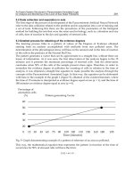
HelpMate is unique in its ability to call and ride elevators to travel between floors
and buildings. The first installation of HelpMate at Danbury hospital in 1988 used
infrared transmitter/receiver pairs mounted on the robot and in the elevator and in
the ceiling of every elevator lobby. Using this infrared link, the HelpMate
communicated with the central controller, called the elevator to its floor, entered
the elevator while holding the door open, then closed the door and made a floor call
to the desired floor. Once at the requested floor, HelpMate navigated out of the
elevator, closed the door, and signed off with the elevator controller.
Although the algorithin proved robust and is still in use with enhancements,
communications via the infrared sensor proved unreliable, and required too
accurate a positioning in the elevator lobbies. The usual crowd in the elevator
lobbies often made it impossible to be positioned within communication range of
the infrared sensor.
Experimentation with radio communications began in 1991, and that is our current
communication mode. Our elevator controller has transitioned from being an Allen
Bradley programmable logic control (PLC) system to a standard single board
personal computer running elevator control software written in C++ under MS
DOS.
Door openers and annunciators (a light and chime to signal someone on the far side
of a secure door that HelpMate is just outside), also originally employed infrared as
the communication mechanism, and they have proved to be quite adequate and
robust. A wide angle transmitter on the robot using multiple led sources broadcasts
a signal with a very simple encoding to distinguish the robot from other IR sources
in the hospital. This is very much like a remote control for a television set. The
demand for installation cost reduction has forced us to look at radio
communications for these devices, and radio annunciators will soon be offered as
an option.
HelpMate robots use the Arian series of radios, offered by Aironet, a subsidiary of
Telxon, providing RF spread -spectrum communications. The initial
implementation used the 100 series radios which provide point-to-point serial
commurdcations at 9600 baud. The newer radios offered by Aironet are the 600
198
series that facilitate ethernet communications with an effective throughput of
several hundred kiloband. Lucent, Symbol and Proxim are also now offering
spread spectrum wireless communications for hospitals, and we are working to be
compatible with any and all such systems.
Incorporation of the 600 series radios into the HelpMate+ required integrating a
third party TCP/IP stack with the Beta versions of the Arlan 600 series. This
proved to be far more complex than anticipated, and hardware and sottware
modifications were necessary to the HelpMate robot and the elevator controller
software to benefit from this new technology.
The adoption of radio communications in the year 1992, albeit serial at 9600 baud,
paved the way for the concept and development of other cooperating system devices
such as the Supervisory controller and a Robot Monitor. It was during 1992 that
the first multiple robot sites were operational at Danbury and at Stanford University
Medical Center,
Fleet control and systems issues, addressed in subsequent sections, have been the
focus of our efforts since 1992.
6 Evolution in System Software
Over the past decade the HelpMate internals and user interface have undergone
many changes and improvements. Understandably, our initial concern was to prove
that the robot could indeed navigate and avoid obstacles in real world
environments. Once that was accomplished the focus turned to improving the
installations and making the robot easier to use and to service in the field.
6.1 Initial Implementation: A Traditional Application Programming Language
The primitive behavior element for HelpMate is getting down a single hallway
without running into things. A language was developed for specifying the
navigation of a sequence of hallways to reach a destination. The language was
named HAL, for HelpMate Application Language, and consisted of about 5
keywords with arguments to carry out the functions of navigating and turning in
halls along with velocity and acceleration settings. The initial versions of the
HelpMate software included a simple kernel, a file manager and a program
executer to parse, interpret and execute program steps.
HAL was enhanced further to include statements that assisted in the operation of
elevators, automatic doors and annunciators. Our field trials consisted mostly of
keying it, the programs by hand, downloading them to the robot and having them
executed on the robot. A typical user installation could have hundreds of such
programs to enable the robot to travel between several departments and all of the
nursing stations as destinations.
1 £9
While experimenting with sensors, algorithms and parameters in the early days it
was essential that we not waste valuable time going through the cycle of
compilation, linking and downloading to try an idea out. We overcame this by
creating a menu driven user interface for the engineers via which we could change
the application parameters. Using this interface we could change parameters like
the composite map decay rate, the maximum drive deceleration, the sonar firing
sequence, or even add a new sonar sensor anywhere on the robot. This facilitated
quick parameter modifications while experimenting with new sensors or
algorithms.
The application parameter interface is hardly being used today, even by the
installation engineers, and any parameters still in use are being incorporated into
the topography rule file described below. This then guarantees that all application
specific information resides in a single repository. Having this interface available
in the early days was invaluable, however.
6.2 Development of the Topography Data Base: Data and Rule Driven
Behavior
Installation of HelpMates in hospitals required that we come up with an automated
way of generating these programs rather than requiring programs for each route.
We have accomplished tiffs by enhancing a commercial CAD program with a
custom shell specific to our needs and having our installation engineers use this
tool to input hospital topography information. In addition to the layout or
topography provided, the installation engineer is free to add station names and
impose speed or route specific rules on either the entire drawing or on a few halls.
Locations of doors that need to be opened or annunciators that need to be triggered
are also included. Stations are nodes, or locations, where the robot waits to be
serviced.
This rule file and the drawing files generated by the AUTOCAD program are
interpreted and converted to a file known as the Topography by an application
called TopGen. The Topography file is generated both as an ASCII file for human
review and as a binary file for downloading to the robot. Note that this is the only
site specific information used by the HelpMate to generate the menu driven user
interface tailored to the site, to generate the routes to travel between stations, and
to modify the behavior of the robot in a way specific to that particular site. Figure 4
shows the sequence of steps in building the Topography.
200
~_utoCAD
~
Floor
Plans
DXF Files
Topography ~
Generator Rules
(TOPGEN)
Topography ~
Jl ',~lg
f
Simulation:
HALGEN
Program m~j~ii{im
I
Ill
i
D
m i., h,L'~
Figure 4: Topography Development
201
6.3 User Interface
The man-machine interface uses a menu display, with the user making selections
using a numeric keypad. On dispatch using the menus the HelpMate is able to plan
a route to the station specified. This is done by examining all the possible paths
from the current station to the destination and picking the path with the smallest
weight. After optimization, path generation in a very large installation such as
Baylor University Medical Center with 55 stations in 5 buildings with up to 19
floors with 5 elevators and 2.8 km of halls takes 13 seconds on a 68332 processor.
This is an extreme case, because the floors are mostly linked between elevators and
hence the number of potential paths is very large. Modest facilities without
linkages between elevators take only a second or less to compute. The output of the
path generation module is a HAL program such as the one described above.
The path generation module can be run on a desktop PC for debugging and
exhaustive route checking prior to installation. This application is called
HALGEN. It takes as input a Topography file and a script file indicating the
programs to be generated, and creates an ASCII HAL program that can be viewed
or even downloaded to the HelpMate for execution.
Typical installation time for a 400 bed hospital takes of the order of 15 man-days,
of which about 5 man days are in creating the Topography and 5 man-days are
spent on site in testing and training. This is a manageable amount of time, thanks
to the installation tools provided to the engineer.
6.5 Debugging and
Management Tools:
Flight Recorders, Run Logs and
Diagnostics
It soon became apparent that we needed to concentrate on debugging aids for run
time errors and apparently inexplicable situations. We created a HelpMate 'flight
recorder' that saved all data, events and decisions made by the master processor.
This was essentially a large data store of sensor data received with time stamps, the
effect of this data on the composite local map, the pathways detected, the one
chosen, and the final drive commands sent out for each tick. Memory restrictions
only facilitated storage of this cyclic detailed log for about 5 minutes. So, as long
as we got to the robot immediately after the situation happened, we could upload
the log, look at the ASCII data, and decipher the problem.
Perusing the flight recorder in ASCII format proved too tedious. A tool we called
ROMON (Robot Monitor) was developed to depict the data in graphical format.
Figure 3 above shows the output of ROMON. This application runs on our
development PC's, takes as input the flight recorder data and displays a pictorial
image of the robot, its environment and the navigation decisions. ROMON helps
visualize the problem situation and pinpoint the area in the flight recorder that
needs more careful analysis.
202
Flight recorders are rarely taken by the installation engineers now, except under
rare occasions. Automatic methods of saving flight recorders have been developed.
Future enhancements call for the flight recorders to be collected and archived
automatically either on the hard drive or sent to a server on the network for
evaluation.
As robots moved into commercial use, run logs were added to track application
data. These logs are kept permanently in the robot's memory. The data collected
can be classified as either diagnostics or trip related data. The diagnostics data log
captures data every time the power up diagnostics fail, along with detailed failure
information and a time stamp. Other diagnostics logs indicate how often, for
example, the ceiling IR sensors have failed, the vision subsystem has failed, or an
encoder error has caused trip cancellation. The trip log dutifully records the
number of times the HelpMate was dispatched to each station and the number of
times it was successful This information along with the number of hours it has
been in use provides valuable round trip time information to provide data on
justifying cost savings for the customer.
Layers of diagnostics were developed to aid in the diagnosing of hardware and
sensor related problems. Initially raw sensor data was viewed using a primitive
menu interface. Tiffs was refined in a separate menu-driven diagnostics package
that allowed the sophisticated user to issue any command or sequences of
commands to any of the subsystems from the HelpMate master processor, the
68000. This layer was enhanced by adding a graphical view of the robot along with
the raw sensor data. During initial development of the HelpMate, these tools were
critical for engineers working in the field trying to understand the behavior of the
robot, they are now used occasionally by manufacturing and by field service.
Current HelpMates run power-up diagnostics that immediately diagnose and report
any problems that may adversely affect the performance of the robot. This power-
up diagnostics checksums the system software and the Topography, and runs tests
on every sensor in the system. Failures are reported to the user with information on
the failure mode. Drive and sensor failures are pinpointed and reported back to the
hospital staff who are able to relay the information to HRI field service engineers
and greatly assist in speedy problem resolution. These start-up diagnostics insure
safe operation of the robot.
7 Fleet Management
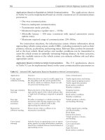
Effective fleet management requires three functions. First, traffic control
algoritluns to ensure efficient usage of systems resources; second, tools to monitor
the real time performance of the robots; and, last, data collection tools to record and
analyze the effective throughput of the system.
2133
7.1 Traffic Control
Traffic control is indispensable for smooth and robust operation of multiple robots
cooperating on delivery tasks with overlapping paths. Hospital hallways are
typically cluttered with meal carts, stretchers, IV posts, laundry carts and
wheelchairs in addition to being high traffic areas which can be crowded with staff
and visitors. These conditions make it virtually impossible for HelpMates to work
together in the same hallway without unduly delaying each other or appearing to
act quite stupidly by blocking each other's way, necessitating intervention by people
or computer controlled supervision.
Contention for elevators is a similar problem. Elevator resources, especially in
hospitals, represent the lifeline of the healthcare delivery system and must therefore
be managed carefully. Since elevators are scarce resources, situations that call for
awkward multiple robot maneuvers and confrontations must be avoided at all costs.
To add to the above, elevator lobbies in hospitals are notorious for being cluttered
with equipment, staff, patients and visitors. Two HelpMates maneuvering in the
elevator lobby vying for a common resource results in unnecessary frustrations and
delays for the impatient hospital staff and patients.
Peer to peer communications between robots to resolve such conflicts were
explored. Two robots could conceivably disentangle themselves from tricky
situations, using local robot to robot communication and deadlock dissolution
algorithms. We noted that the complexity of the algorithms increased rapidly in
order to prevent time consuming and inconsistent behavior when more than 2
robots were involved.
The railroad industry, with similar conflicts, adopted a simple rule: any single
section of track was a one way zone that could be used by only one train at a time.
This idea is called zone control. When two trains must pass or otherwise be in the
same zone, sidings or spurs are provided. A siding is simply a detour off the main
track which converges with the main tracks some distance away. It exists solely for
a train to pull over and wait until after another train has safely passed by. A spur is
a dead end section of track branching off the main line.
Industrial automatic guided vehicles (AGVs), materials transport carts that follow
fixed routes around a factory or warehouse, adopted the basic idea of zone control
from the railroads. They refined the possibilities of traffic control with bumper
blocking, in-floor zone blocking or computer zone blocking mechanisms [44,45].
Bumper blocking is used when the vehicles are travelling along the same direction,
following each other. In-floor zone blocking and computer zone blocking require
physically dividing the guidepath into logical zones and controlling access to them.
Physical site modifications are a part of the AGV system installation, and therefore
pose no problem. Asking HelpMate application engineers to install signals or
traffic lights at intersections is an additional time and cost burden to be avoided if
possible.
204
HelpMate transport systems deploying more than one robot require the functionality
of a central traffic control computer, called the Robot Supervisor, with radio
network communications to all other system component devices. An IBM PC
compatible computer running DOS, MS Windows, Win95 or Windows NT, located
in a secure area, functions as a traffic control by regulating resource allocations
and ensuring system integrity.
HELPMATE SUPERVISOR SYSTEM
MULTIPLE ROBOT MONITO~_~
T.c R II II t
~ .,i ELEVATOR ELEVATOR
I ~ MASTER ~f" INTERFACE CONTROL
U ~ ~ ~ ~. REMOTE MON,TOR
ONE ROBOT
MONITORING ~
~ Ir~ I~
Figure 5: Multiple Robot Supervisory Control System
A combination of spurs and a variation on the AGV idea of computer zone blocking
is used
iii
rnultiple robot traffic control. Coordination of multiple robots is based on
the premise that the site topography can be are divided into distinct areas and
access to those areas is only available on demand to individual robots. Additional
halls, akin to spurs and used solely for deadlock resolution, are added into the
layout of the hospital at the discretion of tile installation engineer.
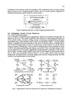
A deadlock situation occurs when two or more HelpMates prevent each other from
completing their missions. The supervisor algorithm detects deadlocks once the
robots are stopped at a junction zone and a robot is requesting resources that have
already been granted to another.
205
Deadlock resolution is dependent on there being a layaway node nearby to which to
re-route one of the robots. The resource granting algorithm ensures that at least
one layaway is available for such deadlock dissolution for each junction zone, thus
preventing, for example, three robots arriving at a three way intersection and
occupying all three layaways. The resolution takes place by sending a re-route
request via a nearby layaway to one of the robots. This causes the robot to re-route
itself to the layaway and await re-entry until the other robots clear the requested
zone. It will then be able to continue on to its final destination.
Z4
Z3
Zl
z2
Figure 6: Zone management and deadlock resolution
In the above figure, HelpMate HM1 wants to navigate from hallway H1 to hallway
I-I3 while HelpMate HM2 is going in exactly the opposite direction. Upon arriving
at layaways L 1 and L3, they both request control of zone Z5 and the layaways
across the zone, each of which has already been granted to the other robot. This
creates a deadlock. The supervisor will reroute the first robot to arrive to one of the
open layaways at the intersection, L2 and L4. This will free one of the robots to
proceed, and subsequently the other robot will return to its desired path.
7.2 Real Time Robot Monitor
The Robot Monitor application was developed to provide the end user with tools to
monitor the status of robots, with the eventual goal of providing central dispatching
and rerouting. In addition to providing status on all robots, the application is able
to alert the user to any emergency situations. This application is written in C++,
runs on an IBM PC under Windows or Windows NT and uses the Topography files
supplied by the installation engineer to display site specific information.
206
Robot status, location and mission information are of prime importance in fleet
management. The user interface is composed of dynamically updated windows
displaying selected robot and elevator information. The main window contains
controls that show the HelpMate's current mission, its current location and
destinations, the current battery voltage, the current time, and a log of the past 100
navigation events.
Event text and action may be customized by the installation engineer to suit
customer requirements. Action options available are entering the event into the
event log, speaking a message or dialing a beeper number.
The application is capable of tracking a specific robot as it moves around in the
hospital. The topography window shows the layout of an installation floor and the
location of all HelpMates within the area of that window. When robot tracking is
requested the topography window is panned as the robot moves out of context.
7.3 Data Collection and Analysis
The HelpMate Monitor generates an ASCII log file of important events. This
information is useful in determining, for example, how many deliveries were made
or for what percentage of time the elevators were being used. The format of the file
is set up so the data file can be imported into Lotus, Excel, Access, dBase, or
similar programs to generate detailed reports.
The largest current installation as of early 1997 is four robots in one hospital. This
will rise to 7 robots by the end of 1997 and eventually we expect to see large fleets
of robots in use.
8 The Future
After a decade of hard work, running close to a man-century of effort, we now have
well over 100 robots nmning around the world, many working 24 hours per day, 7
days per week, in uncontrolled and unsupervised environments.
HelpMate provides simple courier services, requiring a hospital worker to load the
robot and tell it where to go and another hospital worker to unload the robot at the
destination point. Loads to about 1 m 3 and 100 kg can be carried by the robot. At
some point automated loading and unloading will be provided with arms or special
purpose mechanisms on the robot.
Eventually we expect to be selling fleets of robots to hospitals. Those fleets will
include machines of different shapes and sizes to prmdde all manner of materials
207
transport duties, including movement of the large dietary, laundry, supply and trash
carts, movement of specimens within clinical laboratories, and movement of mail in
the offices.
Patient transport may be technically possible, but most hospitals believe that
transporters provide information and comfort that are uniquely human capabilities.
However, in certain circumstances patient transport will be accomplished in the
future with robot assistance.
The thrust of our future work is then toward larger robots, smaller robots, fleet
management and automated loading and unloading. Cost reduction, reliability
improvement, and the addition of features to solve specific customer problems will
continue to be the focus of our efforts on the current machine.
The basic HelpMate robot will not change very much. New generations of
machines will have improved sensors such as lidar sensors to image the ambient
environment and will have improved controls for faster and smoother behavior.
More significant will be the evolution of the system software. We have moved from
a traditional sequential programming language to data and rule driven behavior. In
the future we will have intelligent and serf optimizing systems that learn the
environment on their own, optimally tune their behavior, diagnose themselves and
provide remote diagnostic and service reports. Figure 7 shows this evolution.
By far the most interesting capability for the future will be voice recognition and
speech generation. People already name their robots and visitors and staff talk to
them. When they can talk back, even at the most primitive level, they will be
considered to be far more intelligent and capable to all who interact with them.
Generation 1
(Development)
Generation 2
(Current)
Generation 3
(Future)
Behavior Application
Specification Setup
Procedural Application Parmeters
Language: HAL via Engineering
Menu
Data and Rules: Application Parameters
Topography via Topography
Self-Optimizing
Auto Mapping
of Environment
Self-Tuned
Diagnostics
Engineering Menu
Maintenance Menu,
start-Up
Diagnostics
Remote and Self
Diagnostics
Figure 7: Evolution Of HelpMate System Software
208
References
[l]
Evans, J., Krishnamurthy, B, et.al. "Creating Smart Robots for Hospitals", Proc.,
Robots 13, Washington, DC, 1989
[21
Evans, J., Krishnamurthy, B., et.al. "HelpMate: A Robotic Materials Transport
System." Robotics and Autonomous Systems, 5, 251. 1989.
[31
Robertson, Gordon I., "HelpMate
TM
Delivery Robot Operates Safely Amongst the
General Public." Proceedings, 22 nd ISIR, SME, Detroit, Michigan, 1991.
[41
Engelberger, J.F., "Health-care robotics goes commercial: the HelpMate."
Robitica, 11, 517. 1993.
[51
[61
Evans, J., "HelpMate: An Autonomous Mobile Robot Courier for Hospitals."
Proceedings, IROS 94.
Marr, David, Vision. New York, W.H. Freeman, 1982.
[7] Brady, Michael, et.al., Robot Motion: Planning and Control. Cambridge, MIT
Press, 1983.
[gl
[91
[lO]
[111
[121
Tilove, R. B., 1990, "Local Obstacle Avoidance for Mobile Robots Based on the
Method of Artificial Potentials." 1990 IEEE International Conference on Robotics
and Automation (ICRA90), Cincinnati, Ohio, May 13-18, pp. 566-571.
Kanayama and Miyake, "Trajectory Generation for Mobile Robots",
3 rd
International Symposium on Robotics Research, ISRR-3, Paris, October, 1985.
Barraquand, J., and Latombe, Jean-Claude, '~onholonomic Multibody Mobile
Robots: Controllability and Motin Planning in the Presence of Obstacles." Proc.
1991 IEEE ICRA, Sacramento, CA, April, 199t, p2328.
Nilsson, N.J., "A Mobile Automaton: An Application of Artificial Intelligence
Techniques." Proceedings, IJCAI-1, 1969.
Briot, M. et. al.,
"The
Multi-Sensors Which Help A Mobile Robot Find Its Place"
Sensor Review: 15-19, Jan. 1981
[131
[14]
i15]
Giralt, G., Chatila, R., and Vaisset, M.,
"An
Integrated Navigation and Motion
Control System for Autonomous Multisensory Mobile Robots." Proc., First Int.
Symposium on Robotics Research, ISRR-1, Breton Woods, Nit, August 28, 1983.
Flynn, Anita M., "Redundant Sensors for Mobile Robot Navigation." MIT AI Lab
Technical Report AI-TR-859, 1985.
Biber, C., et. al., "The Polaroid Ultrasonic Ranging System." Audio Engineering
Society 67 ~ Convention, New York, 1980. Available from Polaroid.
[161
[17]
[18]
[19]
[20]
[2]]
[22]
[23]
[241
[251
[26]
[27]
[28]
[291
[30]
[31]
[32]
209
Kadanoff, M.B., "Navigation Techniques for the Denning Sentry." Proceedings
SME Robotics Research Conference, Seottsdale, AZ, Aug 18, 1986.
Moravec, Hans P. and Elfes, Alberto, "High Resolution Maps from Wide Angle
Sonar." Proceedings, 1985 IEEE ICRA, St. Louis, MO, March 1985.
Drum.belier, M., "Mobile Robot Localization Using Sonar." AI Memo 826, MIT
AI Lab, January 1985.
Leonard, J., "Directed Sonar Sensing for Mobile Robot Navigation." Ph.D. Thesis,
Oxford Department of Engineering Science, 1990.
Holland, John., "CA-2 Ultrasonic Collision Avoidance System., Preliminary
Specifications," Cybermotion, Inc., Roanoke, VA, Oct. 1989.
Kay, Leslie, "Transducers." U.S. Patent 4,704,556. Inventor of Sonic Glasses for
the blind ca. 1973.
Kue, Roman and Viard, V.B., "Guiding Vehicles with Sonar: The Edge Problem.'"
Proceedings, IEEE 1988 Ultrasonics Symposium, Chicago, ]L, 1988.
Coles, S.L., Raphael, B., Duda, R., et. al., "Application of Intelligent Automata to
Reconnaissance." Stanford Research Institute Technical Report, November, 1969.
Moravec, H.P., "The Stanford Cart and CMU Rover." Proc. IEEE, 71, 7, p872,
July, 1983. Also CMU Tech Report, same title, 1983.
Thorpe, C., et.al., "Vision and Nivigation for the Carnegie-Mellon Navlab."
PAMI, 10, 3. IEEE, May, 1988.
Low cost vision systems have been developed at USCand MIT, for example.
King, Steven L, "HelpMate: An Autonomous Mobile Robotic Transport System."
Proc. Electronic Imaging East 90. BISCAP, Boston, Oct. 29, 1990.
Evans, J.M., Weiman, C.F.R.W., and King, S.J., 'Wlobile Robot Navigation
Employing Ceiling Light Fixtures", U.S. Patent 4,933,864.
Evans, Weiman, and King, "Visual Navigation and Obstacle Avoidance Structured
Light System." U.S. Patents 4,954,962 and 5,040,116.
Borenstein, J., Everett, H.R., and Feng, L., "Where am I?" Sensors and Methods
for Mobile Robot Positioning. University of Michigan Technical Report UM-
MEAM-94-21.
Kanayama, Y., et.al., "A sonic range finding module for mobile robots."
Proceedings, 14 ~ ISIR, Gothenburg, Sweden, October, 1984.
Kak, A., et.al., "Hierarchical Evidence Accumulation in the PSEIKI System and
Experiments in Model Driven Mobile Robot Navigation." In Uncertainty in
Artificial Intelligence, 5, Elsevier Science Publishers B.V., North-Holland, p 353.
210
[33]
[341
Crowley, J.L., "Navigation for an Intelligent Mobile Robot." IEEE Journal of
Robots and Automation, 1,1, p3 I, 1985.
Cox, I.J., "'Blanche-An Experiment in Guidance and Navigation of an Autonomous
Mobile Robot?' IEEE Transactions Robotics and Automation, 7, 3, p193. 1991.
[351
[36]
[371
[38]
[391
[401
Holland, John, "Sensor Fusion"; and Blachman, S., et.al., "A Fuzzy Logic
Certainty Engine for Evaluating Environmental Threats with Mobile Robots."
Proceedings, Sensors Expo, Sensors Magazine, Chicago, 1992.
Brooks, R.A.,and Cormel, J.H., "Asynchronous distributed control system for a
mobile robot." Proceedings, SPIE, 727, Mobile Robots, October, 1986.
Albus, J.S., et.al, "Theory and Practice of Hierarchical Control." Proc. 23d IEEE
Computer Society International Conference, September, 1981.
Borenstein, J., and Koren, Y., "Real Time Obstacle Avoidance for Fast Mobile
Robots in Cluttered Enviromnents." IEEE 1990 ICRA CH2876-1. Cincinnati, OH,
p572., May 1990.
Lozano-Perez, T., and Wesley, M., "An algorithm for planning collision-free paths
among polyhedral obstalces." Communications of the ACM, 22, 10, 560. 1979.
Crowley, James L., Private Commmdcation, 199 i.
[41]
[421
Cusster, Clive, Dragon. New York, Simon & Schuster, 1990.
US Regulation- FCC Part 15 requirements for unintentional and intentional
radiators.
[431
EC Regulations- EN55011, EN50081-2, EN50082-2, IEC1000-4-1, and IEC 1000-
4-3
[441
Castleberry, Guy A. The AGV Handbook, 1991, Braun-Brum_field, Ann Arbor, MI,
USA.
[45]
Miller, Richard K. Automated Guided Vehicles and Automated Manufacturing,
1987, Society of Manufacturing Engineers, Dearborn,/VII, USA.
Intelligent Wheelchairs and Assistant Robots
Josep Amat
Institut de Robbtica industrial (IRI)- CSIC/UPC
Barcelona (SPAIN)
Abstract :
This work presents an overview over the main technological aids oriented
to the rehabilitation of the physically disabled so that they can get some
independence. These aids range from wheelchairs up to the assistant robots
developed in the
last
years
1. Introduction.
Technological developments in the last years have not only allowed an increase of
the automation level in industry, they have also enabled the manufacture of many
consumer goods. Such goods considered by society as basic elements to improve the
quality of life, are equipments such as automobiles, audio and video devices, electric:
appliances or even personal computers.
Many of these equipments, direct or adequately modified can also constitute
valuable aiding elements to people with physical disabilities produced by diseases,
accidents or also to persons with physical limitations due to old age.
The current availability of equipments that constitute today valuable aids for
disabled people, come from an increasing number of specialized companies that
respond to the needs of a demand more and more important. On the other side, these
companies have available an increasing range of components and devices originally
addressed to industrial automation, but that, conveniently adapted, also allow the
automation of lighting systems, ventilation, and access to or manipulation of the
most common home elements. These elements start to be used by persons that suffer
from important deficiencies in their motor capabilities [1].
The companies specialized in providing technological equipment to physically
disabled persons to increase their independence, offer everyday new technological
resources, ranging from new materials to robotics. These companies also rely on the
support of many research centers, making possible with this cooperation to
significantly increase the market supply of this kind of aids and to appreciably
reduce their cost. Thus, more potential users can reach these products, fig. 1.
2. Technological aids for mobility
One of the most usual disabilities of old people is their lack of mobility. This
disability make them unable not only to move outside, in public thoroughfare, but
even to carry out the necessary short runs at home.
The use of wheelchairs, that started to be developed at the beginning of this
century, has enabled to provide a very efficient solution to the need of mobility,
212
without any other external aid, provided the impaired person can use his or her
upper limbs.
Computers
Electronic
devices
Adaptation of \ ! Multimedia
electrical
appliances \
/
equipment
Adaptation of ~ \ / / New
industrial equipment \ \ / / materials
Eqo, pmo°,II RESE C,
II oupp,,
Acceptance of
technolog;~al ///" \\
Preference for
a,ds ~ ~ co%~ional
Fig. 1 Impact of technological advances in the supply of aids for disabled.
The use of wheelchairs has expanded enormously in the second half of this century,
but only recently, in the last years, they have started to be motorized. Consequently,
they also can be used by people with motor impairment in their upper limbs,
severely enough to impede their manual propulsion. It is specially the development
of technologies tied to automation and even those developed for mobile robots, what
have allowed to build wheelchairs endowed with a control unit to facilitate its
driving. With these more advanced wheelchairs, even people with very low
remaining motion in their hands can drive them without any external aid.
Nowadays, motorized wheelchairs can be driven by means of intelligent
controllers. These are microcomputer based controllers enabling the chair to carry
out straight line trajectories independently of terrain irregularities, to change
direction incrementally or to rotate in place, fig.2. Each user needs his own adapted
interfaces, according to his deficiency, to control the wheelchair [2]. For instance,
these interfaces could be adapted to detect the head movements when the user can
not use his hands.
With the aim to control the trajectories with the support of a microcomputer,
these wheelchairs are endowed with angular encoders in their steering wheels. The
encoders supply the data required to measure runs of the order of millimeters, and
consequently it is possible to calculate, at every moment, the wheelchair trajectory
and adjust it to the set points given by the user. This procedure allows to detect the
wheelchair deviations produced by the terrain unevenness or its irregularities, and to
compensate them. In the same way, it allows to memorize trajectories and to
perform automatically their inverse runs. This facility allows to go out from
constrained spaces, avoiding the great amount of maneuvers that would be necessary
driving the chair manually. This is the case, for instance, of leaving a narrow bath-
room or an elevator.
These intelligent wheelchairs are still little accepted by users, but not due to their
cost, since the additional cost of electronics with respect to the cost of the motorized
wheelchair is not very relevant. Acceptability is limited by a technological factor,
that still predispose negatively most of the potential users.
213
Such intelligent controllers can also benefit from other advances reached in the field
of autonomous navigation or mobile robots [3]. For instance, endowing the
wheelchair with absolute positioning systems, GPS type, or with obstacle detection
systems. Such systems enable to have available motorized wheelchairs with aids for
navigation in urban environments, even for the severely disabled.
The efforts carried out with the aim to endow wheelchairs with the possibility to
go up and down stairs has achieved, technically speaking, positive results, fig. 3.
But, their high cost and their bulkiness, together with the availability of other
existing aids to go up vertical unevenness, has had as a consequence that these kind
of wheelchairs are scarcely used.
COMPUTER CONTROL
sT T
ANOUI ~QR TP, Jk JIE CTOR Y
"
AUTOMATIC OBS
~ f
I"~°°"m°"l I 'NTE~ I /
Fig. 2 Control structure of an intelligent Fig. 3 Wheelchair with caterpillar
wheelchair to up and down stairs
On the other hand, some efforts have been done in the design of new chairs and the
study of the materials to use, to build wheelchairs adequate to practice some kind of
sports or physical activities. Nowadays, with very light wheelchairs having an
ergonomic design, it is possible to practice athletics, basketball, cycling or even to
fly with delta wings, fig. 4.
Fig. 4 Possibility for a disabled to practice sports
214
3. Prosthetic elements
Robotics advances are also applicable to the development of aids oriented to the
rehabilitation of people with muscular atrophy or amputees, which, due to this
impairment have missed the mobility of one or more of their limbs.
The development of arms and legs, either prosthesis or orthesis, started in the
seventies and has already attained remarkable performances. With current
technology it is possible to build arms or legs with a physical appearance, totally
mimetic to human's. This fact makes them, from this point of view, totally
acceptable. A technological difficulty, presently, comes from the power supply
requirements, specially for lower limbs which consumption is far higher. On the
other side, another difficulty is due to their control, according to the user's will,
every moment of his daily life.
When the physical deficiency comes from a recent amputation or even from a
muscular atrophy, it can be possible to control the joints of a prosthetic arm using
the user own myoelectric signals, those generated by the brain to activate the
muscles in healthy people [4]. In this case the myoelectric signals are acquired by
means of electrodes, are amplified and afterward processed to identify the kind of
movement desired by the user. Fig. 5.
,
Fig. 5 Schema of the control system of a prosthesis by means of myoelectric signals
Some of the problems not still solved are the capabilities to differentiate signals
from noise, and to interpret many orders given by the brain. Currently, only the most
significant orders are interpretable, orders such as up and down, approach and
retrieve the arm or open and close the hand. Imprecision in the interpretation of
these orders forces the user of such devices to initiate a process of learning his new
capabilities, which though they are very few with respect to a healthy arm, enable
the user to recover an important level of his autonomy.
When the physical impairment affects also the generation of the myoelectric
signal, being either due to an injury in the spinal cord or in the brain itself, it is
necessary to foresee an adapted interface. This interface activated by the user's
remaining movements (head, face or mouth movements) constitutes the means of
communication with the computer in order to control the movements of the arm
until the desired actuation is attained.
Apart of the situations in which the motorized prosthesis are indispensable, as in
the case of amputees of the two arms, their acceptability is still very low, even
considering the degree of perfection attained in their aesthetics. The Waseda hand,