Anatomy of a Robot Part 14 docx
Bạn đang xem bản rút gọn của tài liệu. Xem và tải ngay bản đầy đủ của tài liệu tại đây (332.19 KB, 20 trang )
Be aware that certain communication protocols cannot use retransmission as a tool
to decrease errors. Video and audio links, for example, cannot use retransmission. Video
and audio streams cannot pause while the data is retransmitted because the screen will
go blank. These data streams must be continuously available at the transmitter and rely
entirely on unidirectional data transmission (which we’ll discuss shortly).
CHANNEL TUNING
A bidirectional communications link can be optimized in real time by sending control
information in both directions. Channels can change over time and sometimes need tun-
ing to work properly. Some communication protocols have built-in control signals and
specified tuning algorithms that keep the communication link healthy and robust. The
following methods can be used to tune a system:
■ Power A data communication link will often work better if more power is used
to transmit each bit. The Eb/No ratio is directly affected. The receiver can meas-
ure the signal strength it is receiving from the transmitter. If it determines the sig-
nal is too weak, the receiver can send a request to the transmitter to boost its power
when transmitting. In the same manner, the transmitter can request the receiver to
boost its transmitting power. This technique can be used in all bidirectional com-
munication links as long as the power stays within limits.
What can be done with power control, however, is limited. Too much power can
pollute the spectrum and make it impossible for any communication link to func-
tion properly. A properly constructed power control protocol for a communication
link often includes a limit on the power that is received. If a receiver senses too
much signal strength coming in from a transmitter, it can request the transmitter
to decrease the signal strength to an acceptable level. After all, the signal for one
receiver may just be the noise for another receiver. Some cooperation is therefore
required.
The Code Division Multiple Access (CDMA) protocol uses just such a power con-
trol protocol to optimize the communication link. This technique is especially use-
ful in situations where a cellular phone is moving from one area to another in a
car. The cellular base stations used by the phone change as the phone moves. To
make sure the phone is well behaved and doesn’t disturb the neighboring phones,
power control is used. Here are some web sites and PDF files describing the tech-
nique further:
■ www.comsoc.org/livepubs/surveys/public/2000/dec/dukic.html
■ www.commsdesign.com/main/2000/09 /0009feat3.htm
■ />246 CHAPTER NINE
09_200256_CH09/Bergren 4/17/03 11:24 AM Page 246
■ Code changes If a communication link begins to deteriorate, another technique
that can be used is a coding change. By prior agreement, the receiver and trans-
mitter can pause and change coding methods. Stronger error correction codes
translate directly to a coding gain that can be added to the Eb/No. As we discussed
before, this generally means that an extra amount of redundant data will be sent
in one form or another. Since extra data will be sent over the channel, and since
the channel’s Eb/No value is already marginal, it makes sense to move to a lower
bandwidth for the data transmission. If less actual data is sent, more redundant
data can be appended, and the channel power per bit remains the same.
A specific example of this can be found in MPEG video transmissions. Most
MPEG transmissions are unidirectional, but some video links do have reverse con-
trol channels of a much lower bandwidth. Although video may be sent over uni-
directional satellite links, the reverse control channel can be established over the
phone.
At the transmitter site, an MPEG compressor takes a video signal and compresses
it using the MPEG algorithms. The compressor has a choice of several compres-
sion algorithms that can squeeze the video picture down to smaller and smaller
amounts of data (at the cost of picture quality). The compressor then encodes the
MPEG data for transmission through the channel using Viterbi and RS codes that
append redundant data. The receiver uses the Viterbi and RS codes to eliminate
errors and then decompresses the video picture.
If the receiver cannot correct all the errors, the picture will begin to break up. The
receiver can use the reverse control link to request a better channel coding method.
The compressor at the transmitter site then uses a stronger compression algorithm
to reduce the amount of data sent and chooses a stronger Viterbi and RS code com-
bination. The channel coding increases the data back to the original amount again.
The receiver will then be able to correct all the errors and present a clean picture.
The video image may not be as good as before (because of the extra compression),
but at least the images are going through.
UNIDIRECTIONAL COMMUNICATION CHANNELS
We’ve already discussed or mentioned many of the methods used to decrease errors in
communication channels. Except for retransmission requests, which are impossible in
a unidirectional communication channel, most of the same techniques can be used.
We’ll discuss a few more of the protocols used, but we won’t go into great depth.
However, to adequately specify a communications link for a robot, we must understand
the options.
COMMUNICATIONS 247
09_200256_CH09/Bergren 4/17/03 11:24 AM Page 247
We need to realize that a unidirectional communications link can only be used suc-
cessfully if the following two conditions are met:
■ The receiver’s target error rate must be set so it is acceptable given the specifica-
tions for operation. We can pretty well determine ahead of time what error rate
will be acceptable for operation of the robot.
■ The data received at the receiver must be of sufficient quantity and quality to keep
the data rate high enough and the receiver’s error rate below the acceptable target
value.
To accomplish the second goal, we should review the tools available. In the case of
bidirectional communications, we already talked about block encoding, channel tuning,
and retransmission. Since both channel tuning and retransmission are impossible with-
out a reverse communications channel, we should examine encoding further.
We’ve already discussed block encoding and checksums at some length. Parity bits
and RS encoding are tools that can be used in a unidirectional communications link.
Often, the name given to unidirectional error correction methods is forward error cor-
rection (FEC). It has this name because all error correction information moves forward;
no reverse communication link exists. Here are a few sites about FEC:
■ www.its.bldrdoc.gov/fs-1037/dir-016/_2298.htm
■ />■ www.eccpage.com
Two other tools have proven valuable, namely convolution codes and concatenated
codes.
CONCATENATED CODES
The general idea behind concatenated codes is to herd randomly spaced errors into one
spot where we can dispatch them efficiently and reliably. That may be a gross oversim-
plification, but it is the way I view the technique (see Figure 9-12).
Figure 9-12 shows the typical arrangement for a communications system using con-
catenated codes. MPEG video signal data is broadcast in DVB format over satellites
using this type of concatenated coding. We’ll discuss MPEG compression and the DVB
format later. The description of each block within the figure is as follows:
■ MPEG compressor Broadcast video signals, generated by a video camera, are
accepted by the input to the MPEG compressor. The compressor has several dig-
ital signal processing (DSP) computation engines that compress the signal. We
will discuss data compression later.
248 CHAPTER NINE
09_200256_CH09/Bergren 4/17/03 11:24 AM Page 248
COMMUNICATIONS 249
FIGURE 9-12 Satellite video broadcasting: concatenated coding showing
the introduction and correction of errors
09_200256_CH09/Bergren 4/17/03 11:24 AM Page 249
■ RS encoder The compressed signal is sent into an RS encoder that adds check-
sum data as discussed previously.
■ Interleaver An interleaver is a data shuffler that takes adjacent bytes and sepa-
rates them. It does not expand the data block it receives, but it rearranges the order
of the bytes in the data block. The goal of an interleaver is to arrange the data so
the deinterleaver can separate adjacent errors, making them stand alone. We’ll see
how that works later.
■ Convolutional codes The convolutional encoder effectively adds extra data to
each data symbol. A couple of different types of convolutional codes exist, the
most popular of which are Viterbi and Turbo codes. These codes tend to expand
the data more than the RS encoding does, except the data is added almost byte by
byte. We’ll discuss these codes shortly.
■ Modulator As discussed previously, the data modulator alters carrier wave-
forms according to the data transmitted. Even after the data is modulated once,
the resulting waveform may be modulated a second time to step it up in frequency
for specific communication frequency bands.
■ Channel The data communications channel is taken to be a standard commu-
nications link (such as a satellite link) with errors added as the result of interfer-
ence and noise.
■ Demodulator A demodulator basically has the reverse function of a modulator.
Often, the frequency will be stepped back down once with a first demodulator
stage. The data will then be separated from the carrier wave in the final demodu-
lation step. The demodulator data output should be identical to the modulator’s
data input, save for the errors introduced by the channel noise.
■ Convolutional decoder The convolutional decoder effectively strips off the
extra data the convolutional encoder added to each data symbol. The decoder must
match the convolutional encoder. The output of the decoder should be identical to
the input to the convolutional encoder, save for the errors introduced by the chan-
nel noise.
■ Deinterleaver The deinterleaver is a data shuffler that takes adjacent bytes and
separates them. It does not expand the data block it receives, but it rearranges the
order of the bytes in the data block. The goal of a deinterleaver is to separate adja-
cent errors (bursts of errors) coming out of the decoder. This makes each bit error
stand alone. We’ll see how that works later.
■ RS decoder The RS decoder, as discussed previously, strips off the checksum
data and corrects errors as discussed previously. The output of the RS decoder,
assuming all channel errors are corrected, is identical to the data output from the
MPEG compressor.
250 CHAPTER NINE
09_200256_CH09/Bergren 4/17/03 11:24 AM Page 250
■ MPEG decompressor The decompressor has a DSP compute engine that
decompresses the MPEG video data. The output of the decompressor is a broad-
cast video signal suitable for viewing.
Figure 9-12 shows the distribution of errors in an MPEG satellite transmission and
helps explain why concatenated codes work so well. The figure shows the errors pres-
ent in the DVB communications link. Errors are shown as tic marks on the time graphs
to approximate the distribution over time. This shows the relative action of the various
concatenated coding blocks. The following describes the action of each block in the fig-
ure with concentration on the handling of errors:
■ MPEG compressor
■ RS encoder
■ Interleaver
■ Convolutional codes
■ Modulator
With luck and proper design, none of these five preceding blocks adds errors to the
data. The modulator is the one block capable of introducing partial errors in the sense
that it provides D/A functions. No analog signal is ever perfect. A good modulator will
not add any significant errors.
Channel
The data communications channel is taken to be a standard communications link with
errors added as the result of interference and noise. Data errors might occur at random
intervals, or in concentrated bursts. Such errors are as follows:
■ Random errors Random errors are the easiest to fix. The existing concatenated
codes are well suited to fixing random errors.
■ Bursts of errors The existing concatenated codes are reasonably well suited to
fixing bursts of errors. The convolutional codes tend to concentrate errors into short
bursts anyway. Naturally, if too many errors occur, they cannot all be corrected.
■ Regularly space errors The existing concatenated codes have the most trouble
with errors that occur at regular intervals. The RS block codes, in particular, are
weakest at correcting such errors. This is not to say that these codes will not take
care of errors distributed in such a manner. Just be careful designing a communi-
cation link if the noise is organized in some way.
■ Demodulator By and large, a demodulator will not add much noise to the sig-
nals in the channel. It will add a small amount, but by the time a demodulator is
COMMUNICATIONS 251
09_200256_CH09/Bergren 4/17/03 11:24 AM Page 251
finished with its job, all the channel noise has been turned into digitized noise,
data with some errors in it. The random noise from the channel is shown
unchanged after demodulation.
■ Convolutional decoder The convolutional decoder tends to gather errors
together and correct them. When it fails, it lets through a burst of errors. By and
large, it tends to gather errors together in time. This is a most useful function
because it will make the output of the deinterleaver very predictable. The noise is
shown gathered into bursts after the convolutional decoder.
■ Deinterleaver The deinterleaver takes the bursts of errors that come out of the
convolutional decoder and spreads them out evenly in time. This sets them all up
individually to be picked off by the RS decoder and corrected. The noise is shown
spread out into a regular pattern after the deinterleaver.
■ RS decoder The RS decoder, as discussed previously, is capable of correcting
multiple byte errors in a block of data. Most concatenated codes are constructed
in such a way that the burst of errors coming out of the convolutional decoder does
not, in general, contain more bytes than the RS decoder is capable of correcting.
The noise is shown completely corrected after the RS decoder. This finished the
stated goal of showing how the concatenated codes work. In practice, of course,
some noise always gets through.
■ MPEG decompressor The MPEG decompressor does not add any errors to the
data stream.
DVB concatenated codes are covered further at www.csee.wvu.edu/ϳmvalenti/
documents/milcom00.ppt. Such codes are used in the transmission of video data over
satellite links.
CONVOLUTIONAL CODES
Convolutional codes increase the amount of data redundancy in a data stream. The
decoders have memory within them and delay the output of data for a short while.
Redundant data can be added in a couple of different ways.
Expanding the Bandwidth
Certainly, redundant data can simply be added to the existing data. If this is done, then
extra bandwidth is required to transmit the extra data. We can illustrate this describing
Viterbi codes.
Viterbi Encoder (in the Transmitter) When we can expand the bandwidth, Viterbi
codes specify a state machine that has the unexpanded data as an input. The state
252 CHAPTER NINE
09_200256_CH09/Bergren 4/17/03 11:24 AM Page 252
machine creates the output data. The state machine changes states depending on the
flow of input data bits. Each one and zero from the unexpanded data does two things:
■ Changes states The state machine changes state for each one and zero coming
in from the unexpanded data input.
■ Outputs data Each time the state machine receives an input bit and changes
state, it outputs some data. In general, more bits are output than are input, so the
Viterbi encoder expands the data.
Since more than just two states exist in the Viterbi state machine, each state change
excludes some states in favor of the two states that are the only possible results of the
change. If, for example, the state machine has four states, then a one or a zero can only
make the state machine change to one of two different states. The other two states are
prohibited changes. This is the key to how the Viterbi decoder corrects errors.
Viterbi Decoder It’s a great oversimplification, but here’s a brief explanation of how
the Viterbi decoder corrects errors. The Viterbi decoder knows a priori how the Viterbi
encoder functions. Since the decoder knows the behavior of the encoder, it can detect
suspicious data altered by the noise in the channel. The random changes caused by the
noise cannot fully mimic the activity of the encoder. Thus, the decoder can detect signs
of tampering.
The decoder accepts input bits coming directly out of the channel through the demod-
ulator. The decoder also has a state machine that changes states based on the received
data bits. As the expanded input data is received, the decoder state machine does two
things:
■ Changes state As expanded data bits are received from the demodulator, they
are decoded to determine the next state of the decoder state machine. The history
of the state changes is accumulated back a few cycles.
■ Outputs data As the decoder state machine changes states, it triggers an exam-
ination of the historical state change data. If the historical data all makes sense,
then the decoder outputs the unexpanded data that is stored in the historical data.
In general, the output has fewer bits than the input. This is how the Viterbi decoder
retrieves the original unexpanded data.
The decoder does not output any unexpanded data until it is satisfied it has combed
errors out of the input stream. It will save up data until this is the case. The decoder
looks back over the recent history of state changes to see if those changes make sense.
If the history looks suspicious, the Viterbi decoder considers the fact that one or more
of the received data bits may have been wrong. One by one, the decoder looks into
recent history, examines each recent input bit that was received, and considers what
COMMUNICATIONS 253
09_200256_CH09/Bergren 4/17/03 11:24 AM Page 253
would happen if that bit were in error. The decoder determines what the hypothetical
history would have looked like in this case. If the hypothetical history looks much bet-
ter, the decoder gives weight to the fact that the input bit may have been in error. Once
the decoder finds the most satisfactory hypothetical history, it outputs that hypotheti-
cal data as the real, corrected, unexpanded data.
As we mentioned before, if the Viterbi decoder cannot correct all the errors, it at least
collects them all in one place. Because it stores up the data history before deciding and
making an output, it will output all the recent errors in a burst as it fails in its task. Even
in failure, this is a key to success. The deinterleaver spreads out the burst of errors so
the RS codes can correct them. Picture the Viterbi decoder giving up, but sweeping its
mistakes into one corner and pointing them out to the RS decoder so they can be cleaned
up there instead.
As a reminder, this version of Viterbi coding pertains to the case where the trans-
mitting Viterbi encoder can expand the data before transmission. The encoder thus
organizes the unexpanded data into expanded data that has some recognizable patterns
in it. These recognizable data patterns are what the decoder looks at to determine if the
received, expanded data is suspicious. The metric the decoder uses to examine data is
the Hamming distance (the total number of bit differences) between the actual received
data and the hypothetical received data.
The Viterbi algorithm comes built in to many standard communication systems. The
single most important thing to keep in mind when using the Viterbi algorithm is that it
comes in varying degrees of strength based on certain parameters. If the parameters can
be varied, the stronger codes will tend to expand the data more.
The following web sites describe Viterbi coding further:
■ (follow the links)
■ />viterbi.htm
■ www.cim.mcgill.ca/ϳlatorres/Viterbi/va_main.html
Bandwidth Limited
Sometimes there is no extra bandwidth to work with, and we cannot use Viterbi coding
to expand the data at all. If we want to make some of the transmitted data redundant,
then we must throw away some bandwidth. A bit less of the original data is transmitted,
but the bandwidth is filled up with some redundant data. The overall bandwidth remains
unchanged.
The operator of the communication link must decide how much data bandwidth to
give up. Trellis coding and Viterbi decoding can be used. These codes expand the data
254 CHAPTER NINE
09_200256_CH09/Bergren 4/17/03 11:24 AM Page 254
by a definitive amount based on the coding strength. The operator of the communica-
tion link can select a code and decrease the input data by just the right amount so the
coding expansion fills up the channel bandwidth.
Remember, the goal of this type of encoding is to organize the input data with rec-
ognizable patterns so the decoder can determine if the channel noise has altered it. The
technique generally used to accomplish this is to sacrifice some of the symbol positions
in the symbol constellation.
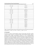
Suppose, for example, that the symbol constellation looks like Figure 9-10 showing
64 QAM, which we’ve seen before. In the case of QAM that is not encoded, all transi-
tions are possible. The signal can move from any X mark to any other X mark to signal
the transmission of 6 more bits (2
6
ϭ 64). But it is possible to restrict the possible tran-
sitions in a recognizable way. If, for instance, it was only possible to jump from one X
mark to just 32 other X marks, then only 5 bits would be transmitted by the transition
(2
5
ϭ 32). The data rate would be cut in half, but the signal would have to follow a dis-
tinct set of rules that would be known to the decoder. The decoder would then be in a
better position to detect errors by the means, outlined earlier.
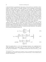
One other technique for restricting the transitions the symbols can make is to liter-
ally provide extra symbol positions. Consider, for the moment, a 16 QAM system with
the symbol constellation shown in Figure 9-13.
It’s possible to double the number of symbol positions to make a 32 QAM system
and to double them again to make a 64 QAM system. The symbols in the 32 QAM sys-
tem can be arranged in any geometric arrangement but are best packed into an approx-
imation of a circle (see Figure 9-14).
COMMUNICATIONS 255
FIGURE 9-13 16 QAM
09_200256_CH09/Bergren 4/17/03 11:24 AM Page 255
If the 16 QAM system is still going to transmit the equivalent of 4 bits per symbol,
the encoder can pack in redundant data by restricting the 32 or 64 different symbol loca-
tions that will be permitted transitions. This effectively puts an identifiable pattern into
the data without expanding the bandwidth. The Viterbi decoder can still be used, but it
uses the distance between symbols as a metric as it looks for suspicious data transitions.
Turbo Coding
Some advances have been made since Viterbi brought out his codes in the late ‘60s.
Viterbi decoder complexity tends to grow exponentially for stronger coding gains.
Classical turbo codes have been out for a while, with much better results, but the clas-
sical turbo codes have some limits, reaching a limit short of the Shannon capacity limit.
In addition, the classical turbo codes are complex to compute and use expensive hard-
ware. Turbo product coding (an improvement on classic turbo codes), is more promis-
ing. The technique allows a determined communications link designer to get arbitrarily
close to Shannon’s capacity limit, sending as much data through a channel as the S/N
ratio will allow. A good deal of computation is required, but the computations tend to
be iterative and lend themselves to an implementation in silicon. Performance is largely
bounded by memory limits.
Turbo product codes replace the entire RS, Viterbi concatenated chain. The per-
formance delivered can bring the BER curve within an arbitrarily small number of dB
256 CHAPTER NINE
FIGURE 9-14 32 QAM and 64 QAM
09_200256_CH09/Bergren 4/17/03 11:24 AM Page 256
of the Shannon limit. The coding is similar to the block coding of RS, with data and
checksum bytes, but it has several differences.
First and foremost, whereas RS has a row of data and checksum bytes, the turbo prod-
uct codes have a three-dimensional structure. Checksums are computed for all three
dimensions for the data: x, y, and z. In this way, the original data is given error-
correcting checksums in multiple directions. The decoder has a relatively simple com-
pute engine. The decoder works on one checksum at a time, doing x, y, and z vector
checksums in separate calculations. Every time the decoder compute engine makes cor-
rections on a vector, it changes the results in the other two dimensions. Once the decoder
has been used on all the vectors in all three dimensions, the entire process can start over.
The decoder can process the data as many times as needed to make the data as perfect
as possible. The more times the decoder is used, the better the results. If the data is
known to have many noise errors, the decoder can be used several times. If the data is
known to be fairly clean, the decoder can be used one or two times. Sufficient infor-
mation is built into the originally transmitted data so the decoder knows when to stop
iterating through the received data.
The following web site and PDF files have further descriptions of turbo codes:
■ www-ext.crc.ca/fec/Compare_Ref2.pdf
■ www.ee.vt.edu/ϳyufei/turbo.html
INTERLEAVER
Interleaving is a way of spreading out errors. Often, an error-correcting scheme will
break down if the errors occur in a regular pattern. Viterbi codes, for instance, will
gather errors into concentrated bursts. An interleaver takes adjacent data and moves
them apart, much like a deck of cards is shuffled. The data is not expanded, just
rearranged. The encoder can interleave the data before transmission, and the decoder
can deinterleave the data on reception. Interleaving can be done in many different ways,
each of which conveys specific advantages and disadvantages.
Here’s the bottom line on interleaving. In general, if interleaving is used within a stan-
dard communications link protocol, all the options are already specified. In this case,
no choices will affect the performance of the communications link. More information
can be found at these sources
■ www.es.lth.se/home/jht/interleaverdownload.html
■ www.comblock.com/download/com1016.pdf
■ www.cs.ucl.ac.uk/staff/jon/talks/rtpi/sld001.htm
Here interleaving is used with compression, not coding. See slides 3, 4, and 5.
COMMUNICATIONS 257
09_200256_CH09/Bergren 4/17/03 11:24 AM Page 257
Shared Access
Communication links are often used by multiple communications entities: sources and
destinations. Sometimes the entities are in separate computers; sometimes they are in
separate processes in the same computer. If a link has multiple sources and destinations,
they have to contend for the use of the communications link. Often, the physical layer
will not allow them all to use the communications link at the same time. The designer
of the communications link must devise a strategy that enables each communications
entity the maximum amount of access to the corresponding communications entity on
the other end of the link. Given that a limited amount of bandwidth exists in the com-
munications link, the designers have to watch out for many different requirements.
BANDWIDTH
Every communication session between entities has different bandwidth requirements.
The requirement for bandwidth may change over time. Some sessions will require a
very steady bandwidth, and some sessions will suddenly require a large percentage of
the available bandwidth. These sessions will present various types of demands on the
bandwidth.
Raw Bandwidth
The different communications sessions may all have different requirements for
bandwidth.
Changes in Bandwidth
Some communication sessions have bandwidth requirements that change unpredictably.
On a shared environment, it often takes time to negotiate for more (or less) bandwidth.
It takes time to conclude such negotiations, which time must be taken into account by
the designer.
Further, the different communication sessions may all have changing requirements
for bandwidth. This presents a classical problem of how to pack all the competing
requirements into the available bandwidth. Even if enough bandwidth exists to satisfy
the arithmetic total of all the required bandwidths, it still may not be possible to pack
them together inside the channel. This problem is reduced to a classic mathematical
packing problem. This problem is akin to trying to pack different-sized blocks inside a
box. There’s almost no way to do it without wasting space. Even if the blocks could all
258 CHAPTER NINE
09_200256_CH09/Bergren 4/17/03 11:24 AM Page 258
fit at once, there may not be enough time to determine the proper solution. The net result
is that full bandwidth is rarely achieved in these circumstances. For more info, access
the following sites:
■ />Section0102c.html
■ www.nist.gov/dads/HTML/binpacking.html
■ />It should also be noted that some receivers have receiving buffers that must not over-
flow or underflow. This is true of MPEG transmission, so be sure to read the following
section. It’s possible for the channel bandwidth to vary because of errors. This presents
much the same problem as the varying requirements. Sometimes errors must just be
accepted.
Guaranteed Bandwidth
Some communication links require a guaranteed bandwidth. MPEG video data streams
coming back from the robot would, in general, require constant bandwidth. Such band-
width would have to be reserved in advance, or at least not be subject to repeated rene-
gotiation.
Reverse Channel Bandwidth
Bandwidth is often thought of as a one-way parameter. The truth is, if the channel is
bidirectional, then the bandwidth must be sufficient in both directions. This can greatly
complicate systems where bandwidth is arranged at the spur of the moment.
DELAYS
Several types of delays can disrupt a communications link. All communications links
have delay. Even at the speed of light, data can take microseconds to cross a county.
Most electrical signals move far slower than that. Electronic boards for communication
have significant processing time, which will delay data. If real-time control loops
depend on a communication path, then these delays must be calculated into the design
of the system.
In some systems, bandwidth is relinquished when it is not needed. Further, when
bandwidth is needed, it must be requested and granted. The delay in regaining the rights
to the communication channel must be added to the communication delay to determine
the worst-case delay.
COMMUNICATIONS 259
09_200256_CH09/Bergren 4/17/03 11:24 AM Page 259
PRIVACY
We will discuss security and privacy shortly. The only reason to mention privacy here
is that shared communication channels carry an extra risk of eavesdropping. This is
especially true if all users have the option of seeing all the traffic. TCP/IP systems often
have this limitation.
SHARED ACCESS ENVIRONMENT
A system in which multiple entities share the communications link can be designed in
many ways. Sometimes the very nature of the communications environment dictates the
methods used. Here are a couple of considerations a robot designer should take into
account when picking a communications system that will support multiple entities that
share access to the channel.
Closed System
If access to the communications system is restricted, then the designer can generally
count on uniformity of response. The entire system should behave according to the
architecture and protocols envisioned. If the communication link must be shared with
unknown communication entities, then all sorts of problems can arise.
Load Limits
The total amount of communication traffic that a link will bear is often determined by
both the protocol and the users’ actions on the link. It is not unusual for a communica-
tion link to top out at a fraction of the raw bit speed of the link.
Cooperative Users
If the communication entities cooperate, then the usable bandwidth of the communica-
tion link can be increased. If the communication entities can be synchronized, then they
can time-share a communication link fairly efficiently.
TYPES OF SHARED ACCESS
As we mentioned before, cooperation between communication entities that share a com-
munication link is beneficial. Here are a couple of specific types of shared access
260 CHAPTER NINE
09_200256_CH09/Bergren 4/17/03 11:24 AM Page 260
arrangements that are quite general. These same types of shared access arrangements
are used in many different communication standards. If a communication system is
functionally identical to these systems, then the math pencils out the same way. The lim-
its on effective bandwidth are very real.
TIME DIVISION SYSTEMS
Shared access to communications link can be accomplished by dividing the like by time
division, frequency division or code division.
Aloha System
The Aloha communications system was designed so a sender could simply transmit a
packet on the channel whenever it wanted to. If another sender was sending a packet at
the same time, they would collide and both packets would be lost. As more and more
senders compete for the channel, the system rapidly loads down. The way the math pen-
cils out, only 18 percent of the channel’s raw bandwidth is truly available once the
system loads down. Normal 10BT LAN systems work like this; collisions ruin the data
packets. As a 10BT LAN starts to load down with more and more users, the overall
effective bandwidth of the 10BT systems is not the raw bit speed of 10 Mbps but
is closer to 1.8 Mbps. On a 10BT LAN, this limit can only be improved if the users
cooperate.
Slotted Aloha
The Aloha system can be improved if the senders are synchronized. Each sender knows
when the timeslots occur and can only start to transmit at the beginning of a timeslot.
Collisions still occur, but this sort of cooperation between senders increases the effec-
tive throughput of the channel to about 35 percent of its raw bit speed.
Reserved Aloha
If the senders politely reserve timeslots in advance, the effective throughput of the chan-
nel increases yet again. Although some bandwidth is wasted making the reservations,
collisions are largely eliminated and the efficiency can be high. Only the reservation
timeslots are wasted. Reservations can be granted in multiple ways, including round-
robin, priority systems, and random selection. It is up to the robot designer to determine
what sort of “request-grant” system to adopt.
COMMUNICATIONS 261
09_200256_CH09/Bergren 4/17/03 11:24 AM Page 261
FREQUENCY DIVISION SYSTEMS
It is certainly possible to put different communication entities on different frequencies
within the allowable communication channel frequencies. Several issues arise, such as
frequency allocation and frequency separation.
Frequency Allocation
All of the same reservation issues of reserving bandwidth are present in frequency divi-
sion systems. If a frequency goes unused, then the bandwidth is wasted. If reservations
are required, then overhead exists for making the reservations.
Frequency Separation
Communication channels on adjacent frequencies must not interfere with one another.
Filters are used to remove adjacent frequencies from a communication band.
Since perfect filters are impossible to make, we must leave extra bandwidth between
frequency bands. It is impossible to pack different frequency bands too close together.
Both the transmitter and receiver run into trouble if they are too close.
A few other problems can crop up when frequency bands are packed close together.
■ Distortion The transmitter may have trouble with intermodulation distortion.
Consider the case where two frequencies, f1 and f2, are amplified and up-converted
together. The result is unwanted distortion signals at frequencies (f2 Ϫ f1) and (f1
ϩ f2). Here is a PDF file and a few URLs speaking about such distortion:
■ www.sinctech.com/pdfs/Intermod.pdf
■ www.audiovideo101.com/dictionary/im-distortion.asp
■ www.atis.org/tg2k/_intermodulation.html
■ ISI If frequencies are too close together, the electronics handling each fre-
quency may have trouble filtering out the adjacent signals. Although frequency
division systems are viable and work fine, time division and code division sys-
tems have stolen the thunder of this technology.
CODE DIVISION SYSTEMS
Code division systems use a form of encryption where each user’s data is invisible to
the other users.
262 CHAPTER NINE
09_200256_CH09/Bergren 4/17/03 11:24 AM Page 262
Code Division Multiple Access (CDMA)
CDMA systems, also known as spread spectrum (SS) systems, generally use a wide
frequency bandwidth. The data for each user is spread across the entire frequency band
using a spreading code. Every user’s communication is broadcast in the band at the
same time, but they do not interfere with one another. Each user gets a unique spread-
ing code that is used to separate users. Because of the nature of the codes, little or no
interference exists between users. Furthermore, no synchronization is required between
the users.
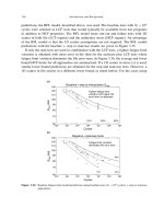
In 1940, Hollywood actress turned inventor Hedy Lamarr copatented a frequency-
hopping device for military use. It’s kind of nice to have her picture in here among all
the men in powdered white wigs (see Figure 9-15). One interesting quote is attributed
to her: “Any girl can be glamorous . . . all she has to do is stand still and look stupid.”
More information on her work can be found at www.inventions.org/culture/female/
lamarr.html and at www.edu-cyberpg.com/Teachers/womenmonth.html#ahedy.
Here’s how the most popular SS systems work. Each user is assigned a coded spread-
ing waveform:
U1code
i
2
COMMUNICATIONS 263
FIGURE 9-15 Hedy Lamarr, pioneer in spread spectrum communications
and actress
09_200256_CH09/Bergren 4/17/03 11:24 AM Page 263
Where code
i
is the user’s unique code that selects the characteristics of the waveform
U(code
i
). These waveforms are typically a series of pulses that have the following char-
acteristics. Whereas ϫ represents a bit by multiplication (correlation):
unless k ϭ i and the two waveforms are synchronized, in which case
In addition, U(code
i
) ϫ B is very small for uncorrelated signals (like radio trans-
missions) that may already exist in the channel. This means that SS signals can coexist
(overlay) in the channel with existing communication users.
In some SS protocols, the data is first modulated by the spreading waveform prior to
transmission. Consider the case where the channel is filled with the waveforms of two
users. We can extract a single user in the following way:
where i and k are different and D
i
is the data from user i.
Similarly, the waveform for user k can be cleanly extracted as well.
On the plus side, SS communications can coexist with existing, uncorrelated com-
munication signals in the channel. This basically allows the channel spectrum to be
reused.
On the minus side, the different codes are not completely orthogonal. The previous
small signal Z is multiplied by the number of other users and can interfere with recep-
tion. This can limit the number of users.
Here are a few PDFs discussing shared access communication links:
■ />■ www.cse.sc.edu/ϳsrihari/csce516/lecnotes/shared.6.pdf
■ .682/www/lec18.pdf
Channel ϫ U1code
i
2 ϭ D
i
ϩ Z Х D
i
Channel ϫ U1code
i
2 ϭ D
i
ϫ U1code
i
2 ϫ U1code
i
2 ϩ D
k
ϫ U1code
k
2 ϫ U1code
i
2
Channel ϫ U1code
i
2 ϭ U1code
i
2 ϫ 1D
i
ϫ U1code
i
2 ϩ D
k
ϫ U1code
k
22
Channel ϭ D
i
ϫ U1code
i
2 ϩ D
k
ϫ U1code
k
2
U1code
i
2 ϫ U1code
i
2 ϭ 1
U1code
i
2 ϫ U1code
k
2 ϭ Z V 1
264 CHAPTER NINE
09_200256_CH09/Bergren 4/17/03 11:24 AM Page 264
Compression
Often, the bandwidth available for digital communication is limited. This may occur for
several different reasons:
■ Regulated spectrum The government may regulate access to the spectrum and
make everyone share it.
■ Cost It is often too expensive to purchase rights to the needed spectrum.
■ Energy As we discussed before, sending bits across a wireless channel literally
requires a sufficiently high Eb/No. In satellite transmission, this fact literally
comes home as satellite batteries and solar panels struggle to provide energy to
each and every bit. Robots in remote locations are often up against this very prob-
lem. Don’t forget one thing though. It takes energy to compress the data in the first
place. The compression process may have to be very energy efficient and the
entire process will have to be analyzed.
Whatever the reason, there is little point in sending useless data across the channel.
Most digital communications can be compressed to a smaller amount of data. Shannon
toyed with this at some length. To test this assertion, pick a few different types of files
on a computer and try to compress them with WinZip.exe, a trademarked program from
WinZip
™
Computing, Inc. It’s presently available for trial use at www.winzip.com/
ddchomea.htm.
The following compression rations can often be achieved:
■ Standard text files A factor of 6 to 10.
■ Program files A factor of 2.
■ Video or graphic files A factor of 1.1.
Try compressing these types of files with the WinZip
™
utility to see what can be
achieved. If the robot’s digital communications must be compressed prior to transmis-
sion, several options are available. WinZip
™
may not be usable on the robot’s computer.
It’s likely that the robot’s operating system software library (or freeware) may already
have compression utilities that can be used. Two basic types of compression are com-
monly used by these programs. These techniques are used in standard compression pro-
grams and can be rewritten to suit the needs of the robot.
Fourier Transforms
Graphics and video transmissions are routinely compressed using Fourier transforms.
In MPEG video compression, the pictures are converted to a series of coefficients that
COMMUNICATIONS 265
09_200256_CH09/Bergren 4/17/03 11:24 AM Page 265