Build A Remote-Controlled Robot Part 5 ppt
Bạn đang xem bản rút gọn của tài liệu. Xem và tải ngay bản đầy đủ của tài liệu tại đây (135.98 KB, 10 trang )
This, however, only works for small adjustments. With the bolt
inserted you can now mark and drill the other holes starting
with the hole in the opposite corner from the bolt. (If you
started with the bottom left hole, drill the upper right next.)
This method and order of marking and drilling helps ensure
the wheels will be straight.
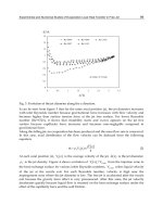
The motorized wheels’ final attachment to the platform is
illustrated in Fig. 1-9. Notice the use of lockwashers. These
washers are very important because they keep the nuts from
coming loose due to vibration caused when the robot travels
over rough surfaces. You should use lockwashers throughout
your robot. Also Fig. 1-9 shows the use of a large bore washer.
This washer should be approximately 2 inches in diameter
with a 3/4-inch bore to allow it to slip over the post of the
motorized wheel. The washer keeps a ridge on the top of the
wheels’ frame from digging into the wooden platform when
the bolts are tightened. Also, the washer helps keep the wheel
sitting level. After the wheels are attached, make a final check
to see that they are straight. Once the two motorized wheels
are mounted, it is necessary to mount a third castor wheel on
the front of the platform.
8 CHAPTER ONE
FIGURE 1-8. Motorized wheels in mounted position.
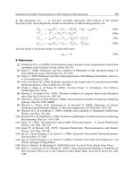
THIRD CASTOR WHEEL
The castor wheel makes the platform level and gives it stability.
The wheel should be about 3 inches in diameter and designed
for heavy-duty use. Depending on the wheel you obtain, you’ll
probably have to stack pieces of plywood between the platform
and the mounting plate of the castor wheel so that the plat-
form sits level. Figure 1-10 shows where on the platform the
wheel is mounted. Remember to make sure that the castor is
centered along the front edge of the platform. A guideline
shown in Fig. 1-10 shows how to do this.
After you find the center point, place the castor wheel on
the platform so that if turned in a circle, the wheel will not pro-
trude past the front edge of the platform. Next mark and drill
the hole for the wheel’s mounting plate. (The diameter of the
THE MOTORIZED PLATFORM 9
FIGURE 1-9. Motorized wheel attachment.
10 CHAPTER ONE
TABLE 1-1. Parts List
AMOUNT
ITEM
2 Motorized wheel
1 Sheet of 24- ϫ 24- ϫ 1/4-inch plywood
1 4-inch-diameter castor wheel
8 2-inch ϫ 1/4-inch-diameter bolt, nut, and lockwasher set
4 3-inch ϫ 1/4-inch-diameter bolt, nut, and lockwasher set
2 2-inch ϫ 3/4-inch-diameter bore washer
1 Auto fiberglass repair kit, including cloth and resin
1 Can spray paint (color of your choice)
FIGURE 1-10. Location of castor wheel.
holes depends on the wheel you have obtained.) As I noted
before, you will probably have to stack some plywood spacers
(use the wood left over from when you made the platform)
between the wheel and the platform. These spacers are made by
tracing around the castor’s mounting plate and then marking
and drilling the mounting holes as you did for the platform.
When you stack the spacers, all the holes should line up.
Bolt the castor wheel and spacers to the platform as shown
in Fig. 1-11. Then using a small level, check to see that the
platform sits correctly. If the level of the platform is slightly off,
this can be corrected by placing washers between the stacked
plywood and the mounting plate of the castor until level.
FINISHING TOUCHES
After you have mounted all three wheels, remove them and
paint the platform. This not only makes the platform look bet-
THE MOTORIZED PLATFORM 11
FIGURE 1-11. Castor wheel attachment.
ter, but makes it water resistant. You may opt as I have to
fiberglass the platform. Fiberglass also provides water protec-
tion and adds strength to the platform. Fiberglass is very easy
to work with (especially on a flat surface) so if you follow the
directions on the package, you should have no problems. If
you do use fiberglass, use a kit with a clear resin so you can
locate and redrill all the mounting holes in the platform. Once
you have fiberglassed and painted, you can reattach the three
wheels. Figure 1-12 shows the completed platform.
12 CHAPTER ONE
FIGURE 1-12. Completed platform (bottom view).
BODY FRAMEWORK
Q
uestor’s body is made from five 8-foot ϫ 1-inch ϫ 1-inch ϫ
1/8-inch strips of aluminum angle. I chose this material
over wood or plastic because while slightly more expensive, it
is stronger and more lightweight. Also, if care is taken, alu-
minum is relatively easy to work with. The aluminum angle is
used to form two boxes. These boxes are called the upper
framework and the lower framework. Once joined, they make
up Questor’s body.
Before the boxes are constructed each section of alu-
minum angle used to make up that portion of the body is
marked and drilled with holes to be used later in the robot’s
construction. These predrilled holes are best made when the
framework is in pieces rather than when assembled. A chart
will list how to assemble each box so all the predrilled holes
are in their proper locations when the framework is complete.
Remember to take your time and not to cut or drill the alu-
minum angle until you have checked your measurements or
hole locations against the book.
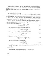
CUTTING ALUMINUM
Figure 2-1 shows how to cut each of the five aluminum strips
into the pieces that make up Questor’s framework. Cut the
strips with a hack saw and use a miter box to achieve straight
cuts. Be careful not to cut the aluminum before you have
checked your measurements.
13
CHAPTER
TWO
Copyright 2002 The McGraw-Hill Companies, Inc. Click Here for Terms of Use.
FIGURE 2-1.
Aluminum angle cutting guide.
14
Once you have cut the strips into pieces, separate them
so that you have four 36-inch, four 6-inch, six 10-inch, and
ten 20-inch pieces. Keep all the extra aluminum for use
later.
Now that you have the various pieces grouped together,
check to see if they are all the same length. If the pieces are
slightly unequal, simply choose the shortest piece of that
group and cut or file the others down to match it. After all the
pieces have been grouped and trimmed, they must be
predrilled and some pieces precut before assembly. This
preparation will save you a lot of time and trouble later.
DRILLING AND CUTTING THE SECTIONS
Many of the holes to be drilled now are not utilized until later
in the robot’s construction. It is much easier to drill them now
while the framework is in pieces than later when it is assem-
bled. All the cuts to be made consist of 45-degree angles.
These cuts are at the ends of one side of some of the pieces
and allow them to be joined into squares with no overlap.
Figure 2-2 shows an example of this.
Figures 2-3 through 2-26 illustrate how each piece of alu-
minum is drilled or cut. Each figure consists of two rectan-
gles; one rectangle represents each of the outer surfaces of
BODY FRAMEWORK 15
TABLE 2-1. Parts List
AMOUNT
ITEM
5 8-foot ϫ 1-inch ϫ 1-inch ϫ 1/8-inch angle aluminum
50 1/8-inch pop rivet (and rivet gun)
8 1-inch ϫ 5/32-inch-diameter bolt, nut, and
lockwasher set
6 1-inch ϫ 1/4-inch-diameter bolt, nut, and
lockwasher set
1 Vacuum cleaner kit
FIGURE 2-2. Angles cut so pieces can be joined at corners.
FIGURE 2-3. Drilling and cutting guide.
FIGURE 2-4. Drilling and cutting guide.
FIGURE 2-5. Drilling and cutting guide.