Build A Remote-Controlled Robot part 12 docx
Bạn đang xem bản rút gọn của tài liệu. Xem và tải ngay bản đầy đủ của tài liệu tại đây (101.62 KB, 10 trang )
between each component. The last thing to do at this stage is
to connect the pump to the container using a 2-foot piece of
fish tank air hose tubing; the tube should go from the pump
through the cap of the container and rest on the bottom of the
container. Smear some silicone glue around the connection at
the pump to ensure a waterproof fit. The dispenser is now
ready for mounting and wiring.
The drink dispenser is held in place using four 1-inch
angles like those used in the remote control system. There
are four predrilled holes in the framework to accept the
angles that are held in place by four 1-inch ϫ 1/4-inch-diam-
eter bolt, nut, and lockwasher sets. Bolt the angles in place,
then position the drink dispenser on them. Take a pencil or
pen and mark via the underside of the base where the unit
sits on the angles. Remove the drink dispenser’s container
and drill four 1/8-inch-diameter holes where marked; be
careful not to damage the parts already mounted on the
board. Now bolt the unit in place using four 1-inch ϫ 1/8-
inch-diameter bolt, nut, and lockwasher sets. Replace the
container on the base and reconnect the tube from the pump
to the container. Once the drink dispenser is in place, a sec-
ond length of tubing must be run from the output spout of
the pump into the robot’s left arm and out of a predrilled
hole at the bottom of the arm. The tubing should be approxi-
mately 20 inches in length. Also smear some silicone glue
where the tubing connects to the pump. Figure 5-13 shows
how to run the tubing through the arm and how to form the
spout at the robot’s wrist where people fill their cups. The
last step in installing the drink dispenser is to wire the pump,
control switch, and power together. Figure 5-14 shows how
to wire the dispenser in place. Note the use of a 20-amp
fuse; this fuse is short circuit protection for the pump, and
the wire leading to its holder must be soldered in place. The
control button mounted on the robot’s wrist will also have to
be soldered with two wires running the length of the arm,
one that runs down the framework to the barrier strips on
the remote control board.
After the dispenser is wired in place, it must be tested.
Place a small amount of water in the container, then turn on
78 CHAPTER FIVE
the robot’s main power switch and press the switch on the
robot’s wrist. The pump will begin to hum and once it primes
itself, water will flow out the spout at the underside of the
robot’s wrist; this completes the drink dispenser. Next you’ll
install Questor’s head.
ARMS AND SUBSYSTEMS 79
FIGURE 5-13. Tank-to-arm tubing.
FIGURE 5-14. Drink dispenser wiring diagram.
THE HEAD
Questor’s head is basically an automobile dome light with a
white cover made of ceiling light panels. The dome light is
attached to a 9 1/2-inch-square piece of 1/8-inch pressboard
(or plywood; hardboard is easier to cut circles in) which is in
turn mounted at the top of Questor’s upper framework using
three predrilled holes located on the framework. Three metal
tabs located where the light’s base is screwed to the frame-
work act as mounting points for the light’s cover. Figure 5-15
shows the dome light and cover mounting tabs attached to the
robot’s frame.
The mounting tabs for the cover are made from the same
type of sheet metal used to make the container brackets for
the drink dispenser. The tabs should be 2 inches long folded
in the middle with a 1/8-inch hole drilled at both ends. Note
that the holes drilled in the ends of the tabs should be slightly
smaller in size than the diameter of the 1/8-inch sheet metal
screws used to hold the dome light assembly to the robot’s
frame.
The dome light cover, which is actually considered
Questor’s head, is made from a sheet of plastic ceiling light
80 CHAPTER FIVE
FIGURE 5-15. Mounting tabs for the head. Note the auto dome light in place.
panels and eight lengths of plastic angle. The ceiling light
panels are available at most hardware stores and the plastic
angle you need can be purchased at a hobby shop. Figure 5-16
shows the size, shape, and amount of the panels to be cut
from the sheet of plastic ceiling light cover. When cutting the
plastic panels, use a plastic cutting knife that should be avail-
able where you obtain the panels.
Assemble the panels as shown in Fig. 5-17 using the
lengths of plastic angle where the panels meet, and modeling
glue to cement the parts together. After the glue has dried,
place the cover over the dome light so that the tabs on the
framework are inside the cover. The cover is clear enough so
that you will be able to see and mark the hole in the tabs on
the cover. Carefully drill the mounting holes in the cover mak-
ing sure not to crack the plastic. Now attach the cover with
three 1/8-inch sheet metal screws; you can now wire the dome
light.
Figure 5-18 shows how to wire the dome light. The switch
(which should come with the dome light) for the light will
later be mounted on the robot’s skin; for now, simply tape it to
the robot’s frame. Test the light being sure to flip Questor’s
main power switch on before trying the light. Now that the
head has been wired and tested, remove the cover so it will
not be damaged while you complete Questor’s construction.
WIRING THE VACUUM SYSTEM
The final major system to be wired is Questor’s vacuum sys-
tem, the body and motor of which you installed earlier. The
wiring guide that comes with the kit is for installation of the
vacuum in a car, while basically the same type of installation
as here, a few things should be noted. First, the kit comes
with all black wires, not black and red, and the motor itself
has two white leads. The motor was designed to run in the
right direction no matter what lead is connected to positive or
negative terminals of a battery. Just be careful not to connect
both leads to the same terminal or in this case, the power grid.
Also, on the switch you will see three tabs where the wires are
ARMS AND SUBSYSTEMS 81
82 CHAPTER FIVE
FIGURE 5-16. Head panels to be cut from ceiling light panel.
ARMS AND SUBSYSTEMS 83
FIGURE 5-17. Inside view of assembled head panels.
FIGURE 5-18. Head wiring diagram.
connected. Use the bottom tab and the one marked “open” on
the side of the switch. This allows the motor to run only when
the door of the vacuum outlet is open. Finally, the fuse for the
system is built into the wire itself; be sure the fuse is in place
before attempting to use the vacuum. Once wired, all that is
needed to activate the system is to open the door to the vacu-
um outlet and attach the vacuum cleaner hose. This com-
pletes all of Questor’s major systems.
84 CHAPTER FIVE
SKIN AND FINISHING
TOUCHES
N
ow that Questor’s major systems have been completed and
installed, it is time to improve his appearance. In this chap-
ter you will attach Questor’s metal skin, mount the controls, and
install other options from previously installed systems that make
the robot function and appear as a butler, true to his robot ser-
vant theme. Also in this section you’ll paint the metal skin and
add the robot’s serving tray. Before the skin can be attached,
Questor’s remote control (RC) system, drink dispenser, and
arms must be removed. Be sure that you remove the aluminum
angles used to mount the RC system and drink dispenser.
SKIN
Questor’s skin consists of metal flashing. This material is a
very thin sheet metal that can be easily cut with a pair of scis-
sors; the flashing comes in various lengths and widths. You’ll
need approximately two 8-foot rolls that are 10 inches wide;
from this will be cut three 3-foot panels and two 2-foot pan-
els. The two 2-foot panels will be cut in half lengthwise to give
you four 5-inch-wide sections. Out of these seven sections will
be cut the final skin panels.
Beginning with the three 3-foot panels, trim them so that
you have three panels that are 2 1/2 feet long and 9 inches
wide. Next cut the four 5-inch-wide panels so that they are 19
inches long. Once all the skin panels have been cut, they are
attached to the framework from the inside. You can cut and
85
CHAPTER
SIX
Copyright 2002 The McGraw-Hill Companies, Inc. Click Here for Terms of Use.
tuck the skin around obstructions along the framework; just
be sure it looks good from the outside. The panels are held
in place by strips of double-sided tape running the length of
the inside of the framework. Also, sheet metal screws along
the outside of the framework secure the panels in place. The
screws are placed at all the 1/8-inch-diameter predrilled
holes on the sides of the framework. Figure 6-1 illustrates
where and how the panels are attached. You will need to cut
a hole in the center of the lower rear panel to accommodate
the vacuum cleaner motor that protrudes there, and a square
on the lower front panel to accommodate the vacuum outlet.
86 CHAPTER SIX
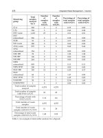
TABLE 6-1. Parts List
AMOUNT
ITEM
2 Roll of aluminum flashing
# Rolls of double-sided tape, 1/2 inch wide
2 Roll of aluminum tape, 6 inches wide
1 2- ϫ 4-foot sheet of hardboard
2 2-inch section of aluminum angle
5 1-inch section of aluminum angle
# 1/8-inch sheet-metal screws
2 Auto courtesy lights
2 SPST switch
1 12-volt horn
1 Rubber gasket (big enough to fit around the vacuum system’s
motor)
1 4-foot length of rubber floor matting
12 1/8-inch-diameter washer
1 Light-up bow tie
1 9-volt battery
1 Can black spray paint
1 Can white spray paint
1 TV snack tray
1 Roll black foam insulation tape
1 1- ϫ 2-foot sheet of felt
The metal skin panels cover all of the robot’s body except
for the rear of the upper framework and the top of the lower
framework. These openings will be covered with utility panels
which, when removed, allows access to Questor’s innerwork-
ings. The utility access panels are made of 1/8-inch-thick
hardboard. The panels are then covered with aluminum tape
to give them a metallic look that matches the rest of the body.
The panel for the rear of the upper framework measures 9
ϫ 29 inches; it is held to the framework by five 1-inch-long
mounting tabs made from leftover aluminum angle used to
make the framework. These tabs are riveted to the rear frame-
work and the panel in turn is screwed to the tabs with 1/8-inch
sheet metal screws, like those used to secure the metal skin to
the framework. Figure 6-2 shows how each tab is to be drilled
to accept both the rivet and the screw. Rivet the five tabs along
the rear framework where 1/8-inch holes have been drilled pre-
viously. Match the 1/8-inch holes on the tab with that on the
framework and rivet it in place, as shown in Fig. 6-3.
To locate where on the panel to drill the holes for the
screws used to attach it, place the panel on the inside of the
SKIN AND FINISHING TOUCHES 87
FIGURE 6-1. Skin attachment to framework.