Control Problems in Robotics and Automation - B. Siciliano and K.P. Valavanis (Eds) Part 3 pdf
Bạn đang xem bản rút gọn của tài liệu. Xem và tải ngay bản đầy đủ của tài liệu tại đây (1.33 MB, 25 trang )
32 M. Uchiyama
application of the load-sharing control to robust holding. It also presented a
couple of advanced topics of recent days and future directions of research; the
topics include cooperative control of multiple flexible-robots, robust holding
with slip detection, and practical implementation of the hybrid position/force
control without using any force/torque sensors but with exploiting the motor
currents. In concluding this chapter, we should note that application of the-
oretical results to real robot systems is of prime importance, and that efforts
in future research will be directed in this direction to yield stronger results.
References
[1] Bonitz R G, Hsia T C 1994 Force decomposition in cooperating manipulators
using the theory of metric spaces and generalized inverses. In:
Proc 1994 IEEE
Int Conf Robot Automat.
San Diego, CA, pp 1521-1527
[2] Chiacchio P, Chiaverini S, Siciliano B 1995 Redundancy resolution for two
cooperative spatial manipulators with a sliding contact. In:
Theory and Prac-
tice of Robots and Manipulators, Proc RoManSy 10.
Springer-Verlag, Vienna,
Austria, pp 119 124
[3] Dauchez P, Zapata R 1985 Co-ordinated control of two cooperative manipu-
lators: The use of a kinematic model. In:
Proc 15th Int Syrup Industr Robot.
Tokyo, Japan, pp 641-648
[4] Fujii S, Kurono S 1975 Coordinated computer control of a pair of manipulators.
In:
Proc ~th IFToMM World Congr.
Newcastle-upon-Tyne, UK, pp 411-417
[5] Hayati S 1986 Hybrid position/force control of multi-arm cooperating robots.
In:
Proc 1986 IEEE Int Conf Robot Automat.
San Francisco, CA, pp 82-89
[6] Kim J-S, Yamano M, Uchiyama M 1997 Lumped-parameter modeling for co-
operative control of two flexible manipulators.
1997 Asia-Pacific Vibr Conf.
Kyongju, Korea
[7] Koivo A J, Bekey G A 1988 Report of workshop on coordinated multiple robot
manipulators: planning, control, and applications.
IEEE J Robot Automat.
4:91-93
[8] Kosuge K, Koga M, Nosaki K 1989 Coordinated motion control of robot arm
based on virtual internal model. In:
Proc 1989 IEEE Int Conf Robot Automat.
Scottsdale, AZ, pp 1097-1102
[9] Kosuge K, Oosumi T 1996 DecentrMized control of multiple robots handling
an object. In:
Proc 1996 IEEE/RSJ Int Conf Intel Robot Syst.
Osaka, Japan,
pp 318-323
[10] MeClamroch N H 1986 Singular systems of differential equations as dynamic
models for constrained robot systems. In:
Proe 1986 IEEE Int Conf Robot
Automat.
San Francisco, CA, pp 21-28
[11] Munawar K, Uchiyama M 1997 Slip compensated manipulation with cooper-
ating multiple robots.
36th IEEE Conf Decision Contr.
San Diego, CA
[12] Nakano E, Ozaki S, Ishida T, Kato I 1974 Cooperational control of the anthro-
pomorphous manipulator 'MELARM'. In:
Proc ~th Int Syrup Industr Robot.
Tokyo, Japan, pp 251-260
[13] Perdereau P, Drouin M 1996 Hybrid external control for two robot coordinated
motion.
Robotica.
14:141-153
Multirobots and Cooperative Systems 33
[14] Sun D, Shi X, Liu Y 1996 Modeling and cooperation of two-arm robotic sys-
tem manipulating a deformable object. In:
Proe 1996 IEEE Int Conf Robot
Automat.
Minneapolis, MN, pp 2346-2351
[15] Svinin M M, Uchiyama M 1994 Coordinated dynamic control of a system of
manipulators coupled via a flexible object. In:
Prepr ~th IFAC Syrup Robot
Contr.
Capri, Italy, pp 1005-1010
[16] Takase K, Inoue H, Sato K, Hagiwara S 1974 The design of an articulated
manipulator with torque control ability. In:
Proc ~th Int Syrup Industr Robot.
Tokyo, Japan, pp 261-270
[17] Tara T J, Bejczy A K, Yun X 1988 New nonlinear control algorithms for
multiple robot arms.
IEEE Trans Aerosp Electron Syst. 24:571-583
[18] Uchiyama M 1990 A unified approach to load sharing, motion decomposing,
and force sensing of dual arm robots. In: Miura H, Arimoto S (eds)
Robotics
Research: The Fifth International Symposium.
MIT Press, Cambridge, MA,
pp 225-232
[19] Uchiyama M, Dauchez P 1988 A symmetric hybrid position/force control
scheme for the coordination of two robots. In:
Proc 1988 IEEE Int Conf Robot
Automat.
Philadelphia, PA, pp 350-356
[20] Uchiyama M, Dauchez P 1993 Symmetric kinematic formulation and non-
master/slave coordinated control of two-arm robots.
Advanc Robot. 7:361-383
[21] Uchiyama M, Delebarre X, Amada H, Kitano T 1994 Optimum internal force
control for two cooperative robots to carry an object. In:
Proc 1st World Au-
tomat Congr.
Maui, HI, vol 2, pp 111 116
[22] Uchiyama M, Iwasawa N, Hakcmori K 1987 Hybrid position/force control for
coordination of a two-arm robot. In: Proc t987
IEEE lnt Conf Robot Automat.
Raleigh, NC, pp 1242-1247
[23] Uchiyama M, Kanamori Y 1993 Quadratic programming for dextrous dual-arm
manipulation. In:
Robotics, Mechatronics and Manufacturing Systems, Trans
IMACS/SICE Int Symp Robot Mechatron Manufaet Syst.
Elsevier, Amster-
dam, The Netherlands, pp 367- 372
[24] Uchiyama M, Kitano T, Tanno Y, Miyawaki K 1996 Cooperative multiple
robots to be applied to industries. In:
Proc 2nd World Automat Congr. Mont-
pellier, France, vol 3, pp 759 764
[25] Uchiyama M, Konno A 1996 Modeling, controllability and vibration suppres-
sion of 3D flexible robots. In: Giralt G, Hirzinger G (eds)
Robotics Research,
The Seventh International Symposium.
Springer-Verlag, London, UK, pp 90-
99
[26] Uchiyama M, Yamashita T 19!)1 Adaptive load sharing for hybrid controlled
two cooperative manipulators. In:
Proc 1991 IEEE Int Conf Robot Automat.
Sacramento, CA, pp 986-991
[27] Unseren M A 1994 A new technique for dynamic load distribution when two
manipulators mutually lift a rigid object. Part 1: The proposed technique. In:
Proc 1st World Automat Congr. Maui, HI, vol 2, pp 359-365
[28] Unseren M A 1994 A new technique for dynamic load distribution when two
manipulators mutually lift a rigid object. Part 2: Derivation of entire system
model and control architecture. In:
Proc 1st World Automat Congr. Maui, HI,
vol 2, pp 367-372
[29] Walker I D, Freeman R A, Marcus S I 1991 Analysis of motion and internal
force loading of objects grasped[ by multiple cooperating manipulators.
Int J
Robot Res.
10:396-409
[30] Wen J T, Kreutz-Delgado K 1992 Motion and force control of multiple robotic
manipulators.
Automatica. 28:729-743
34 M. Uchiyama
[31] Williams D, Khatib O 1993 The virtual linkage: A model for internal forces
in multi-grasp manipulation. In:
Proc 1993 IEEE Int Conf Robot Automat.
Atlanta, GA, pp 1025-1030
[32] Yamano M, Kim J-S, Uchiyama M 1997 Experiments on cooperative control of
two flexible manipulators working in 3D space.
1997 Asia-Pacific Vibr Conf.
Kyongju, Korea
[33] Yukawa T, Uchiyama M, Nenchev D N, Inooka H 1996 Stability of control
system in handling of a flexible object by rigid arm robots. In:
Proc 1996
IEEE Int Conf Robot Automat.
Minneapolis, MN, pp 2332-2339
[34] Zheng Y F, Chen M Z 1993 Trajectory planning for two manipulators to deform
flexible beams. In:
Proc 1993 IEEE Int Conf Robot Automat.
Atlanta, GA,
vol 1, pp 1019-1024
Robotic Dexterity via Nonholonomy
Antonio Bicchi, Alessia Marigo, and Domenico Prattichizzo
Centro "E. Piaggio", Universit£ degli Studi di Pisa, Italy
In this paper we consider some new avenues that the design and control of
versatile robotic end-effectors, or "hands", are taking to tackle the stringent
requirements of both industrial and servicing applications. A point is made
in favour of the so-called minimalist approach to design, consisting in the
reduction of the hardware complexity to the bare minimum necessary to
fulfill the specifications. It will be shown that to serve this purpose best,
more advanced understanding of the mechanics and control of the hand-
object system is necessary. Some advancements in this direction are reported,
while few of the many problems still open are pointed out.
1. Introduction
The development of mechanical hands for grasping and fine manipulation
of objects has been an important part of robotics research since its begin-
nings. Comparison of the amazing dexterity of the human hand with the
extremely elementary functions performed by industrial grippers, compelled
many robotics researchers to try and bring some of the versatility of the an-
thropomorphic model in robotic devices. From the relatively large effort spent
by the research community towards this goal, several robot hands sprung out
in laboratories all over the world. The reader is referred to detailed surveys
such as e.g. [15, 34, 13, 27, 2].
Multifingered, "dextrous" robot hands often featured very advanced me-
chanical design, sensing and actuating systems, and also proposed interesting
analysis and control problems, concerning e.g. the distribution of control ac-
tion among several agents (fingers) subject to complex nonlinear bounds.
Notwithstanding the fact that hands designed in that phase of research were
often superb engineering projects, the community had to face a very poor
penetration to the factory floor, or to any other scale application. Among the
various reasons for this, there is undoubtedly the fact that dextrous robot
hands were too mechanically complex to be industrially viable in terms of
cost, weight, and reliability.
Reacting to this observation, several researchers started to reconsider the
problem of obtaining good grasping and manipulation performance by using
mechanically simpler devices. This approach can be seen as an embodiment
of a more general, "minimalist" attitude at robotics design (see e.g. works
reported in [3]). It often turns out that this is indeed possible, provided that
more sophisticated analysis, programming and control tools are employed.
36 A. Bicchi et al.
The challenge is to make available theoretical tools which allow to reduce the
hardware cost at little incremental cost of basic research.
One instance of this process of hardware reduction without sacrificing
performance can be seen in devices for "power grasping", or "whole-arm
manipulation", i.e. devices that exploit all their parts to contact and constrain
the manipulated part, and not just their end-effectors (or fingertips, in the
case of hands). From the example of human grasp, it is evident that power
grasps using also the palm and inner phalanges are more robust than fingertip
grasping, for a given level of actuator strength. However, using inner parts
of the kinematic chain, which have reduced mobility in their operational
space, introduces important limitations in terms of controllability of forces
and motions of the manipulated part, and ensue non-trivial complications
in control. Such considerations are dealt with at some length in references
[37, 36],
and will not be reported here.
In this paper, we will focus on the achievement of dexterity with simpli-
fied hardware. By dexterity we mean here (in a somewhat restrictive sense)
the ability of a hand to relocate and reorient an object being manipulated
among its fingers, without loosing the grasp on it. Salisbury [23] showed first
that the minimum theoretical number of d.o.f.'s to achieve dexterity in a
hand with rigid, hard-finger, non-rolling and non-sliding contacts, is 9. As a
simple explanation of this fact, consider that at least three hard-fingers are
necessary to completely restrain an object. On the other hand, as no rolling
nor sliding is allowed, fingers must move so as to track with the contact point
on their fingertip the trajectory generated by the corresponding contact point
on the object, while this moves in 3D space. Hence, 3 d.o.f.'s per finger are
strictly necessary. If the non-rolling assumption is lifted, however, the situa-
tion changes dramatically, as nonholonomy enters the picture. The analysis
of manipulation in the presence of rolling has been pioneered by Montana
[25], Cai and Roth [9], Cole, Hauser, and Sastry [11], Li and Canny [20].
In this paper we report on some results that have been obtained in the
study of rolling objects, in view of the realization of a robot gripper that
exploits rolling to achieve dexterity. A first prototype of such device, achieving
dexterity with only four actuators, was presented by Bicehi and Sorrentino
[5]. Further developments have been described in [4, 22].
Although nonholonomy seems to be a promising approach to reducing the
complexity, cost, weight, and unreliability of the hardware used in robotic
hands, it is true in general that planning and controlling nonholonomic sys-
tems is more difficult than holonomic ones. Indeed, notwithstanding the ef-
forts spent by applied mathematicians, control engineers, and roboticists on
the subject, many open problems remain unsolved at the theoretical level, as
well as at the computational and implementation level.
The rest of the paper is organized as follows. In Sect. 2. we overview
applications of nonholonomic mechanical systems to robotics, and provide
a rather broad definition of nonholonomv that allows to treat in a uniform
Robotic Dexterity via Nonholonomy 37
way phenomena with a rather different appearance. In Sect. 3. we make the
point on the state-of-the-art in manipulation by rolling, with regard to both
regular and irregular surfaces. We conclude the paper in Sect. 4. with a
discussion of the open problems in planning and controlling such devices.
2. Nonholonomy on Purpose
A knife-edge cutting a sheet of paper and a cat failing onto its feet are
common examples of natural nonholonomic systems. On the other hand, bi-
cycles and cars (possibly with trailers) are familiar examples of artificially
designed nonholonomic devices. While nonholonomy in a system is often re-
garded as an annoying side-effect of other design considerations (this is how
most people consider e.g. maneuvering their car for parking in parallel), it
is possible that nonholonomy is introduced on purpose in the design in or-
der to achieve specific goals. The Abdank-Abakanowicz's integraph and the
Henrici-Corradi harmonic analyzer reported by Neimark and Fufaev [30] are
nineteenth-century, very ingenuous examples in this sense, where the
non-
holonomy of rolling of wheels and spheres are exploited to mechanically con-
struct the primitive and the Fourier series expansion of a plotted function,
respectively.
Another positive aspect of nonholonomy, and actually the one that mo-
tivates the perspective on robotic design considered in this paper, is the
reduction in the number of actuators it may allow. In order to make the idea
evident, consider the standard definition of a nonholonomic system as given
in most mechanics textbooks:
Definition 2.1.
A mechanical system described by its generalized coordi-
nates q = (ql, q2,. • •, q~)T is called nonholonomic if it is subject to constraints
of the type
c(q(t),/l(t)) = O, (2.1)
and if there is no equation of the form
~(q(t)) = 0
such that de(q(t)) _
dt
c(q(t),q(t)).
If linear in it, i.e. if it can be written as
c(q, cl) = A(q)/t = 0,
a constraint is called Pfa~an.
A Pfaffian set of constraints can be rewritten in terms of a basis G(q) of
the kernel of A(q), as 1
1 in more precise geometrical terms, the rows of
A(q)
are the covector fields of
the active constraints forming a codistribution, and the columns of G(q) are
a set of vector fields spanning the annihilator of the constraint codistribution.
If the constraints are smooth and independent, both the codistribution and
distribution are nonsingular.
38 A. Bicchi et al.
~1 = G(q)u (2.2)
This is the standard form of a nonlinear, driftless control system. In the
related vocabulary, components of u are "inputs". The non-integrability of
the original constraint has its control-theoretic counterpart in Frobenius The-
orem, stating that a nonsingular distribution is integrable if and only if it is
involutive. In other words, if the distribution spanned by G(q) is not involu-
tive, motions along directions that are not in the span of the original vector
fields are possible for the system.
From this fact follows the most notable characteristic of nonholonomic
systems with respect to minimalist robotic design, i.e. that they can be driven
to a desired equilibrium configuration in a d-dimensional configuration man-
ifold using less than d inputs. In a kinematic bicycle, for instance, two inputs
(the forward velocity and the steering rate) are enough to steer the system to
any desired configuration in its 4-dimensional state space. Notice that these
"savings" are unique to nonlinear systems, as a linear system always requires
as many inputs as states to be steered to arbitrary equilibrium states (this
property being in fact equivalent to functional controllability of outputs for
linear systems).
Since "inputs" in engineering terms translates into "actuators", devices
designed by intentionally introducing nonholonomic mechanisms can spare
hardware costs without sacrificing dexterity. Few recent works in mechanism
design and robotics reported on the possibility of exploiting nonholonomic
mechanical phenomena in order to design devices that achieve complex tasks
with a reduced number of actuators (see e.g. [39, 5, 12, 35]).
It is worthwhile mentioning at this point that nonholonomy occurs not
only because of rolling, but also in systems of different types, such as for
instance:
- Systems subject to conservation of angular momentum, as is the case of
the falling cat. This type of nonholonomy can be exploited for instance for
orienting a satellite with only two torque actuators [26], or reconfiguring a
satellite-manipulator system [29, 17].
- Underactuated mechanical systems, such as robot arms with some free
joints, usually result in dynamic, second-order nonintegrable, nonholo-
nomic constraints [32]. This may allow reconfiguration of the whole system
by controlling only actuated joints, as e.g. in [i, 12].
-
Nonholonomy may be exhibited by piecewise holonomic systems, such as
switching electrical systems [19], or mechanical systems with discontinuous
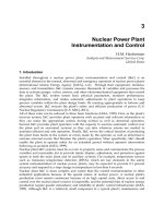
phenomena due to intermittent contacts, Coulomb friction, etc Brock-
ett [8] discussed some deep mathematical aspects of the rectification of
vibratory motion in connection with the problem of realizing miniature
piezoelectric motors (see Fig. 2.1). He stated in that context that "from
the point of view of classical mechanics, rectifiers are necessarily non-
holonomic systems". Lynch and Mason [21] used controlled slippage to
build a 1-joint "manipulator" that can reorient and displace arbitrarily
Robotic Dexterity via Nonholonomy 39
V/////////////A
() ()
() ()
V/////////////A
P~
~J
z
z"-,
y
"z
Vibrating
Actuator
V//////////////A
() ()
() ()
V/////////////A
x
Fig. 2.1. Illustrating the principle of a mechanical rectifier after Brockett. The
tip of the vibrating element oscillates in the x direction, while a variable pressure
against the rod is controlled in the y direction. When the contact pressure is larger
than a threshold y0, dry friction forces the rod to translate in the z direction
most planar mechanical parts on a a conveyor belt, thus achieving control
on a 3 dimensional configuration space by using one controlled input (the
manipulator's actuator) and one constant drift vector (the belt velocity).
Ostrowski and Burdick [33] gave a rather general mathematical model of
locomotion in natural and artificial systems, showing how basically any
locomotion system is a nonholonomic system. In these examples, however,
a more general definition of nonholonomy has to be considered to account
for the discontinuous nature of the phenomena occurring.
- Nonholonomy can be exhibited by inherently discrete systems. The simple
experiment of rolling a die onto a plane without slipping, and bringing it
back after any sufficiently rich path, shows that its orientation has changed
in general (see Fig. 2.2). The fact that almost all polyhedra can be brought
close to a desired position and orientation by rolling on a plate, to be
discussed shortly, can be used to build dextrous hands for manipulation of
general (non-smooth) mechanical parts. Once again, these nonholonomic
phenomena can not be described and studied based on classical differential
geometric tools.
A more general definition than (2.1) is given below for time-invariant sys-
tems:
Definition 2.2. Consider a system evolving in a configuration space Q,
a time set (continuous or discrete) T, and a bundle of input sets A, such,
that for each input set
A(q, t) defined at q E Q, t E T, it holds a : (% t)
q~, q~ E Q, Va E A(q,t). If it is possible to decompose Q in a projection
or
base space B = II(Q) and a fiber bundle 9 c, such that B x jz = Q
and there exists a sequence of inputs in .4 starting at
q0 and steering the',
40 A. Bicchi et al.
system to
q* = a~(q~-l, tn-1) o o al(qo, to),
such that
H(qo) = H(q*)
but
qo ~ q*,
then the system is nonholonomic at
qo-
Fig. 2.2. A die being rolled between two parallel plates. After four tumbles over its
edges, the center of the die comes back to its initial position, while its orientation
has changed
According to this definition, a system is nonholonomic if there exist con-
trols that make some configurations go through closed cycles, while the rest
of configurations undergo net changes per cycle (see Fig. 2.3).
For instance, in the continuous, nonholonomic Heisenberg system
[1] [0]
x2 = 0 ul + 1 , (2.3)
~3 -x2 xl
it is well known (see e.g. [8]) that "Lie-bracket motions" in the direction of
are generated by any pair of simultaneous periodic zero-average functions
ul(-), u2(-). Definition 1 specializes in this case with Q = IR a, ~r = IR+, and
Robotic Dexterity via Nonholonomy 41
Fig. 2.3. Illustruting the definition of nonholonomic systems
A(x, t) = {exp (t(GlUl + G2u2)) x,V piecewise continuous
ui(.)
: [0, t] *
lR, i = 1,2.}. The base space is simply the
xl,x2
plane, and the fibers are
in the x3 direction. Periodic inputs generate closed paths in the base space,
corresponding to a fiber motion of twice the (signed) area enclosed on the
base by the path.
As an instance of embodiment of the above definition in a piecewise holo-
nomic system, consider the simplified version of one of Broekett's rectifiers
in Fig. 2.1. The two regimes of motion, without and with friction, are
E [11 [° 1
9 = u2 = 0 ul+ 1 u2, Y<Y0;
0 0 0
and
[ 11 [1] [0]
~) = u2 = 0 ul+ 1 u2, Y_>Y0,
ul 1 0
respectively. In this case, base variables can be identified as x and y, while the
fiber variable is z. Time is continuous, but the input bundle is discontinuous:
42 A. Bicchi et M.
=
Y<Y0:
x -~ x+f~ul(a)d~;
y , y+f~u2(~)d~;
Z ~ Z;
t
x ~ x + f~ ul(cr)da;
t
Y>Y0 : Y ~ Y+f0u2(cr)d~;
z z+foul( )d .
By changing frequency and phase of the two inputs, different directions and
velocities of the rod motion can be achieved. Note in particular that input ul
need not actually to be tuned finely, as long as it is periodic, and can be fixed
e.g. as a resonant mode of the vibrating actuator. Fixing a periodic Ul(-) and
tuning only u2 still guarantees in this case the (non-local) controllability of
the nonholonomic system: notice here the interesting connection with results
on controllability of systems with drift reported by Brockett ([6], Theorem 4
and Hirschorn's Theorem 5).
Finally, consider how the above definition of nonholonomic system spe-
cializes to the case of rolling a polyhedron. Considering only configurations
with one face of the polyhedron sitting on the plate, these can be described
by fixing a point and a line on the polyhedron (excluding lines that are per-
pendicular to any face), taking their normal projections to the plate, and
affixing coordinates x, y to the projected point, and 0 to the angle of the pro-
jected line, with respect to some reference frame fixed to the plate. Therefore,
Q = ]R 2 x S 1 x F, where F is the finite set of m face of the polyhedron. As
the only actions that can be taken on the polyhedron are assumed to be
"tumbles", i.e. rigid rotations about one of edges of the face currently lying
on the plate that take the corresponding adjacent faces down to the plate,
we take T = IN+ and A the bundle of m different, finite sets of neighbouring
configurations just described. Figure 2.2 shows how a closed path in the base
variables (x,y) generates a 7r/2 counterclockwise rotation and a change of
contact face.
3. Systems of Rolling Bodies
For the reader's convenience, we report here some preliminaries that help in
fixing the notation and resume the background. For more details, see e.g.
[28,
5,
4, 10].
3.1 Regular Surfaces
The kinematic equations of motion of the contact points between two bod-
ies with regular surface (i.e. with no edges or cusps) rolling on top of each
Robotic Dexterity via Nonholonomy 43
other describe the evolution of the (local) coordinates of the contact point
on the finger surface, c~f E IR 2, and on the object surface, C~o E IR 2, along
with the holonomy angle ~ between the x-axes of two gauss frames fixed
on the surfaces at the contact points, as they change according to the rigid
relative motion of the finger and the object described by the relative velocity
v and angular velocity a~. According to the derivation of Montana [25], in the
presence of friction one has
= TfMf&f +ToMo&o;
where KT = Kf + RcKoR¢ is the relative curvature form, Mo, M j, To, Tf
are the object and finger metric and torsion forms, respectively, and
[ cos~ -sin~ ]
Re= -sin~ -cos~b '
The rolling kinematics (3.1) can readily be written, upon specialization of
the object surfaces, in the standard control form
= g1(~)vl + g2(~)v2, (3.2)
where the state vector ~ C IR s represents a local parameterization of the
configuration manifold, and the system inputs are taken as the relative an-
gular velocities vl = w~ and v~ = wy. Applying known results from nonlinear
system theory, some interesting properties of rolling pairs have been shown.
The first two concern controllability of the system:
Theorem a.1.
(from [2O])
A kinematic system comprised of a sphere rolling
on a plane is completely controllable. The same holds for a sphere rolling on
another sphere, provided that the radii are different and neither is zero.
Theorem 3.2. (from [4]) A kinematic system comprised of any smooth,
strictly convex surface of revolution rolling on a plane is completely con-
trollable.
Remark 3.1. Motivated by the above results, it seems reasonable to conjec-
turn that a kinematic system comprised of
almost any pair of surfaces is
controllable. Such fact is indeed important in order to guarantee the possi-
bility of building a dextrous hand manipulating arbitrary (up to practical
constraints) objects.
The following propositions concern the possibility of finding coordinate
transforms and static state feedback laws which put the plate-ball system
in special forms, which are of interest for designing planning and control
algorithms:
44 A. Bicchi et al.
Proposition 3.1. The plate-ball system can not be put in chained form [27];
it is not differentially flat [38]; it is not nilpotent [14].
These results prevent the few powerful planning and control algorithms
known in the literature to be applied to kinematic rolling systems (of which
the plate-ball system is a prototype). The following positive result however
holds:
Theorem 3.3. (from [5]). Assuming that either surface in contact is (lo-
cally) a plane, there exist a state diffeomorphism and a regular static state
feedback law such that the kinematic equations of contact (3.1) assume a
strictly triangular structure.
The relevance of the strictly triangular form to planning stems from the fact
that the flow of the describing ODE can be integrated directly by quadratures.
Whenever it is possible to compute the integrals symbolically, the planning
problem is reduced to the solution of a set of nonlinear algebraic equations,
to which problem many well-known numerical methods apply.
3.2 Polyhedral Objects
The above mentioned simple experiment of rolling a die onto a plane without
slipping hints to the fact that manipulation of parts with non-smooth (e.g.
polyhedral) surface can be advantageously performed by rolling. However,
while for analysing rolling of regular surfaces the powerful tools of differen-
tial geometry and nonlinear control theory are readily available, the surface
regularity assumption is rarely verified with industrial parts, which often have
edges and vertices.
Although some aspects of graspless manipulation of polyhedral objects
by rolling have been already considered in the robotics literature, a complete
study on the analysis, planning, and control of rolling manipulation for poly-
hedral parts is far from being available, and indeed it comprehends many
aspects, some of which appear to be non-trivial. In particular, the lack of
a differentiable structure on the configuration space of a rolling polyhedron
deprives us of most techniques used with regular surfaces. Moreover, pecu-
liar phenomena may happen with polyhedra, which have no direct counter-
part with regular objects. For instance, in the examples reported in Figs. 3.1
and 3.2, it is shown that two apparently similar objects can reach config-
urations belonging to a very fine and to a coarse grid, respectively. In the
second case, the mesh of the grid can actually be made arbitrarily small by
manipulating the object long enough; in such case, the reachable set is said
to be dense.
In fact, considering the description of the configuration set of a rolling
polyhedron provided in Sect. 2. it can be observed that the state space Q is
the union of I copies of ]R 2 x S 1. The subset of reachable configurations from
some initial configuration T¢ is given by the set of points reached by applying
Robotic Dexterity via Nonholonomy
J,/ J J J J J
/J/-//-~ Jz,-J/- Jj j
45
Fig. 3.1. A polyhedron whose reachable set is nowhere dense
Fig. 3.2. A polyhedron whose reachable set is everywhere dense
all admissible sequences of tumbles to the initial configuration. Notice that
the set of all sequences is an infinite but countable set while the configuration
space is a finite disjoint union of copies of a 3-dimensional variety. Thus, the
set of reachable points is itself countable. Therefore, instead of the more
familiar concept of "complete reachability" (corresponding to 7~ = Q), it
will only make sense to investigate a property of "dense teachability" defined
as closure(7~) = Q. In other words, rolling a polyhedron on a plane has
the dense reachability property if, for any configuration of the polyhedron
and every e E l=~+, there exists a finite sequence of tumbles that brings the
polyhedron closer to the desired configuration than ~. We refer in particular
to a distance on Q defined as
I](xl,yl,01,Fi) - (x2,y~,O2,Fj)ll
max{x/(xl - x2) 2 + (Yl -Y2) 2, 101 -021, 1
-e(Fi,Fj)}.
Tile term
discrete
will be used for the negation of
dense.
On this regard, the
following results were reported in [22] (we recall that the defect angle is 2Ir
minus the sum of the planar angles of all faces concurring at that vertex, and
equals the gaussian curvature that can be thought to be concentrated at the
vertex):
Theorem 3.4.
The set of configurations reachable by a polyhedron is dense
in Q if and only if there exists a vertex Vi whose defect angle is irrational
with 7r.
Theorem 3.5.
The reachable set is discrete in both positions and orienta-
tions if and only if either of these conditions hold:
i) all angles of all faces (hence all defect angles) are integer multiples of 7c/3,
and all lengths of the edges are rational w.r.t, each other;
46 A. Bicchi et al.
ii) all angles of all faces (hence all defect angles) are 7c/2, and all lengths o/
the edges are rational w.r.t, each other;
iii) all defect angles are 7r.
Theorem 3.6. The reachable set is dense in positions and discrete in ori-
entations if and only if the defect angles are all rational w.r.t. % and neither
conditions i), ii), or iii) of Theorem 3.5 apply.
Remark 3.2.
Parts with a discrete reachable set are very special. Polyhedra
satisfying condition i) of Theorem 3.2 are rectangular parallelepipeds, as e.g.
a cube or a sum of cubes which is convex. Polyhedra as in condition ii) are
those whose surface can be covered by a tessellation of equilateral triangles,
as e.g. any Platonic solid except the dodecahedron. Condition iii) is only
verified by tetrahedra with all faces equal.
Remark 3.3. Observe that in the above reachability theorems the conditions
upon which the density or discreteness of the reachable set depends are in
terms of rationality of certain parameters and their ratios. This entails that
two very similar polyhedra may have qualitatively different reachable sets.
This is for instance the case of the cube and truncated pyramid reported
above in Figs. 3.1 and 3.2, respectively, where the latter can be regarded
as obtained from the cube by slightly shrinking its upper face. In fact, for
any polyhedron whose reachable set has a discrete structure, there exists
an arbitrarily small perturbation of some of its geometric parameters that
achieves density.
In view of these remarks, and considering that in applications the geomet-
ric parameters of the parts will only be known to within some tolerance, i.e. a
bounded neighborhood of their nominal value, a formulation of the planning
problems ignoring robustness of results w.r.t, modeling errors will make little
sense in applications.
4. Discussion and Open Problems
One way of reducing what is probably the single highest cost source in robotic
devices, i.e. their actuators, is offered by nonholonomy. It has been shown in
this paper how nonholonomic phenomena are actually much more pervasive
in practical applications than usually recognized. However, the real challenge
posed by nonholonomic systems is their effective control, including analysis
of their structural properties, planning, and stabilization. The situation of
research in these fields is briefly reviewed below.
Controllability. A nonholonomic system according to the above definition
may not be completely nonholonomic, i.e. not completely controllable in
some or all of the various senses that are defined in the nonlinear control
Robotic Dexterity via Nonholonomy 47
literature. Detecting controllability is a much easier task for continuous
driftless systems, such as e.g. the case of two bodies rolling on top of
each other (see Eq. 3.1), because of the tools made available by nonlinear
geometric control theory [16, 31]. Even in this case, though, there remains
an open question to prove the conjecture that almost any pair of rolling
bodies are controllable, or in other words, to characterize precisely the
class of bodies which are not controllable, and to show that this subset is
meager. Another question, practically a most important one, is to define
a viable (i.e. computable and accurate) definition of a "controllability
function" for nonholonomic systems, capable of conveying a sense of how
intense the control activity has to be to achieve the manipulation goals,
in a similar way as "manipulability" indices are defined in holonomic
robots.
The controllability question is much harder for discontinuous systems or
for systems with discrete input sets. As discussed above, relatively novel
problems appear in the study of the reachable set, such as density or
lattice structures. Very few tools are available from systems and automata
theory to deal with such systems: consider to this regard that even the
apparently simple problem of deciding the density of the reachable set of
a l-dimensional, linear problem
Xk+l /~xk ~-uk, uk E U, afiniteset
is unsolved to the best of our knowledge, and apparently not trivia] in
general. It is often useful in these problems to notice a possible group
structure in the fiber motions induced by closed base space motions (see
Fig. 2.3): such group analysis was actually instrumental to the results
obtained for the polyhedron rolling problem.
Planning. The planning problem (i.e. the open-loop control) for some par-
ticular classes of nonholonomic systems is rather well understood. For
instance, two-inputs nilpotentiable systems that can be put, by feedback
transformation, in the so-called "chained" form, can be steered using si-
nusoids [28]; systems that are "differentially fiat" can be planned looking
at their (flat) outputs only [38]; systems that admit an exact sampled
model (and maintain controllability under sampling) can be steered us-
ing "multirate control" [24]; nilpotent systems can be steered using the
"constructive method" of [18]. However, as already pointed out, systems
of rolling bodies do not fall into any of these classes. At present, planning
motions of a spherical object onto a planar finger can be done in closed
form, while for general objects only iterative solutions are available (e.g.
the one proposed in [40]).
Stabilization. The control problem is particularly challenging for nonholo-
nomic systems, due to a theorem of Brockett [7] that bars the possibility
of stabilizing a nonholonomic vehicle about a nonsingular configuration
by any continuous time-invariant static feedback. Non-smooth, time-
varying, and dynamic extension algorithms have been proposed to face
48 A. Bicchi etM.
the point-stabilization problem for some classes of systems (e.g. chained-
form). A stabilization method for a system of rolling bodies, or even for
a sphere rolling on a planar finger, is not known to the authors.
References
[1] ArM H, Tanie K, Tachi S 1993 Dynamic control of a manipulator with passive
joints in operational space.
IEEE Trans Robot Automat.
9:85-93
[2] Bicchi A 1995 Hands for dextrous manipulation and powerful grasping: a diffi-
cult road towards simplicity. In: Giralt G, Hirzinger G (eds)
Robotics Research:
The Seventh International Symposium.
Springer-Verlag, London, UK, pp 2-15
[3] Bicchi A, Goldberg K (eds.) 1996 Proc 1996 Work Minimalism in Robotic
Manipulation
1996 IEEE Int Conf Robot Automat.
Minneapolis, MA
[4] Bicchi A, Prattichizzo D, Sastry S S 1995 Planning motions of rolling surfaces.
In:
Proc 1995 IEEE Conf Decision Contr.
New Orleans, LA
[5] Biechi A, Sorrentino R 1995 Dextrous manipulation through tolling. In:
Proc
1995 IEEE Int Conf Robot Automat.
Nagoya, Japan, pp 452-457
[6] Brockett R W 1976 Nonlinear systems and differential geometry.
Proc IEEE.
64(1):61-72
[7] Brockett R W 1983 Asymptotic stability and feedback stabilization. In: Brock-
ett R W, Millmann R S, Sussman H J (eds)
Differential Geometric Control
Theory.
Birkh/~user, Boston, MA, pp 181-208
[8] Brockett R W 1989 On the rectification of vibratory motion.
Sensors and
Actuators.
20:91-96
[9] Cai C, Roth B 1987 On the spatial motion of a rigid body with point contact.
In:
Proc 1987 IEEE Int Conf Robot Automat.
Raleigh, NC, pp 686 695
[10] Chitour Y, Marigo A, Prattichizzo D, Bicchi A 1996 Reachability of rolling
parts. In: Bonivento C, Melchiorri C, Tolle H (eds)
Advances in Robotics: The
ERNET Perspective.
World Scientific, Singapore, pp 51-60
[11] Cole A, Hauser J, Sastry S S 1989 Kinematics and control of a multifingered
robot hand with rolling contact.
IEEE Trans Robot Automat.
34(4)
[12] De Luca A, Mattone R, Oriolo G 1996 Dynamic mobility of redundant robots
using end-effector commands. In:
Proc 1996 IEEE Int Conf Robot Automat.
Minneapolis, MA, pp 1760-1767
[13] Grupen R A, Henderson T C, McCammon I D 1989 A survey of general-
purpose manipulation.
Int J Robot Res.
8(1):38-62
[14] Guyon C, Petitot M 1995 Flatness and nilpotency. In:
Proc 3rd Euro Contr
Conf.
Rome, Italy
[15] Hollerbach J M 1987 Robot hands and tactile sensing. In: Grimson W E L,
Patil R S (eds)
AI in the 1980's and beyond.
MIT Press, Cambridge, MA,
pp 317-343
[16] Isidori A 1995
Nonlinear Control Systems.
(3rd ed) Springer-Verlag, London,
UK
[17] Kolmanovsky I V, McClamroch N H, Coppola V T 1995 New results on control
of multibody systems which conserve angular momentum. J
Dyn Contr Syst.
1:447-462
[18] Lafferriere G, Sussmann H 1991 Motion planning for controllable systems
without drift. In:
Proc 1991 IEEE Int Conf Robot Automat.
Sacramento, CA,
pp 1148-1153
Robotic Dexterity via Nonholonomy 49
[19] Leonard N E, Krishnaprasad P S 1995 Motion control of drift free, left invariant
systems on Lie groups.
IEEE Trans Automat Contr.
40(9)
[20] Li Z, Canny J 1990 Motion of two rigid bodies with rolling constraint.
IEEE
Trans Robot Automat.
6:62-72
[21] Lynch K M, Mason M T 1995 Controllability of pushing. In:
Proc 1995 IEEE
Int Conf Robot Automat.
Nagoya, Japan, pp 112-119
[22] Marigo A, Chitour Y, Bicchi A 1997 Manipulation of polyhedral parts by
rolling. In:
Proc 1997 IEEE Int Conf Robot Automat.
Albuquerque, NM
[23] Mason M T, SMisbury J K 1985
Robot Hands and the Mechanics of Manipu-
lation.
MIT Press, Cambridge, MA
[24] Monaco S, Normand Cyrot, D 1992 An introduction to motion planning under
multirate digital control. In:
Proc 31st IEEE Conf Decision Contr.
Tucson, AZ,
pp 1780-1785
[25] Montana D J 1988 The kinematics of contact and grasp.
Int J Robot Res.
7(3):17 32
[26] Morin P, Samson C 1997 Time varying exponential stabilization of a rigid
spacecraft with two control torques.
IEEE Trans Automat Contr.
42:528-533
[27] Murray R M 1994 Nilpotent bases for a class of non-integrable distributions
with applications to trajectory generation for nonholonomic systems.
Math
Contr Sign Syst.
7:58-75
[28] Murray R M, Li Z, Sastry S S 1994
A Mathematical Introduction to Robotic
Manipulation.
CRC Press, Boca Raton, FL
[29] Nakamura Y, Mukherjee R 1993 Exploiting nonholonomic redundancy of free
flying space robots.
IEEE Trans Robot Automat.
9:499-506
[30] Neimark J I, Fufaev N A 1972
Dynamics of Nonholonomic Systems,
American
Mathematical Society Translations of Mathematical Monographs, 38
[31] Nijemeijer H, van der Schaft A J 1990
Nonlinear Dynamical Control Systems.
Springer-Verlag, Berlin, Germany
[32] Oriolo G, Nakamura Y 1991 Free joint manipulators: Motion control under
second order nonholonomic constraints. In:
Proc IEEE/RSJ Int Work Intel
Robot Syst.
Osaka, Japan, pp 1248-1253
[33] Ostrowski J, Burdick J 1995 Geometric perspectives on the mechanics and con-
trol of robotic locomotion. In: Giralt G, Hirzinger G (eds)
Robotics Research:
The Seventh International Symposium.
Springer-Verlag, London, UK
[34] Pertin-Troccaz J 1989 Grasping: A state of the art. In:
The Robotics Review
/, MIT Press, Cambridge, MA, pp 71-98
[35] Peshkin M, Colgate J E, Moore C 1996 Passive robots and haptie displays
based on nonholonomic elements. In:
Proc 1996 IEEE Int Conf Robot Automat.
Minneapolis, MA, pp 551 556
[36] Prattichizzo D, Bicchi A 1997 Consistent specification of manipulation tasks
for defective mechanical systems.
ASME J Dyn Syst Meas Contr.
119
[37] Prattichizzo D, Bicchi A 1997 Dynamic analysis of mobility and graspability
of generM manipulation systems.
IEEE Trans Robot Automat.
13
[38] Rouchon P, Fliess M, Lgvine J, Martin P 1993 Flatness, motion planning,
and trailer systems. In:
32nd IEEE Conf Decision Contr.
San Antonio, TX,
pp 2700-2705
[39] ScrdMen O J, Nakamura Y 1994 Design of a nonholonomic manipulator. In:
Proc 1993 IEEE Int Conf Robot Automat.
San Diego, CA, pp 8-13
[40] Sussmann H, Chitour Y 1993 A continuation method for nonholonomic path-
finding problems. In:
Proc IMA Work Robot.
Control for Teleoperation and Haptic
Interfaces
Septimiu E. Salcudean
Department of Electrical and Computer Engineering, University of British Columbia
Canada
The concept of teleoperation has evolved to accommodate not only manip-
ulation at a distance but manipulation across barriers of scale and in vir-
tual environments, with applications in many areas. Furthermore, the design
of high-performance force-feedback teleoperation masters has been a signifi-
cant driving force in the development of novel electromechanical or "haptic"
computer-user interfaces that provide kinesthetic and tactile feedback to the
computer user. Since haptic interfaces/teleoperator masters must interact
with an operator and a real or virtual dynamic slave that exhibits signifi-
cant dynamic uncertainty, including sometimes large and unknown delays,
the control of such devices poses significant challenges. This chapter presents
a survey of teleoperation control work and discusses issues of simulation and
control that arise in the manipulation of virtual environments.
1.
Teleoperation and Haptic
Interfaces
Since its introduction in the 1940s, the field of teleoperation has expanded
its scope to include manipulation at different scales and in virtual worlds.
Teleoperation has been used in the handling of radioactive materials, in sub-
sea exploration and servicing. Its use has been demonstrated in space [20], in
the control of construction/forestry machines of the excavator type [36], in
microsurgery and micro-manipulation experiments [33, 39] and other areas.
The goal of teleoperation is to achieve "transparency" by mimicking hu-
man motor and sensory functions. Within the relatively narrow scope of ma-
nipulating a tool, transparency is achieved if the operator cannot distinguish
between maneuvering the master controller and maneuvering the actual tool.
The ability of a teleoperation system to provide transparency depends largely
upon the performance of the master and the performance of its bilateral
controller. Ideally, the master should be able to emulate any environment
encountered by the tool, from free-space to infinitely stiff obstacles.
The need for force-feedback in general purpose computer-user interfaces
has been pointed out in the 1970s [5]. The demand is even higher today,
as performance improvements in computer systems have enabled complex
applications requiring significant interaction between the user and the com-
puter. Examples include continuous and discrete simulation and optimization,
52 S.E. Salcudean
searching through large databases, mechanical and electrical design, educa-
tion and training.
Thus actuated devices with several degrees of freedom can serve as so-
phisticated input devices that also provide kinesthetic and tactile feedback
to the user. Such devices, called "haptic interfaces", have been demonstrated
in a number of applications such as molecular docking [35], surgical training
[42], and graphical and force-feedback user interfaces [25].
The design of haptic interfaces is quite challenging, as the outstanding
motion and sensing capabilities of the human arm are difficult to match. The
performance specifications that haptic interfaces must meet are still being
developed, based on a number of psychophysical studies and constraints such
as manageable size and cost [19]. Peak acceleration, isotropy and dynamic
range of achievable impedances are considered to be very important. A design
approach that considers the haptic interface controller has been presented in
[29].
This chapter is concerned with the design of controllers for teleoperation
and haptic interfaces. A survey of control approaches is presented in Sect. 2.
Interesting teleoperation control research topics, at least from this author's
perspective, are being discussed in Sect. 3. Issues of haptic interface control
for manipulation in virtual environments are discussed in a limited manner
in Sect.4. mainly stressing aspects common to teleoperation.
2.
Teleoperator Controller
Design
The teleoperation controller should be designed with the goal of ensuring
stability for an appropriate class of operator and environment models and
satisfying an appropriately defined measure of performance, usually termed
as
transparency.
2.1 Modeling Teleoperation Systems
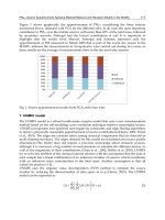
A commonly used teleoperation system model, e.g. [3, 17], is one with five
interacting subsystems as shown in Fig. 2.1. The master manipulator, con-
troller, and slave manipulator can be grouped into a single block representing
the teleoperator as shown by the dashed line. For n-degree-of-freedom manip-
ulation, the teleoperator can be viewed as a 2n-port master-controller-slave
(MCS) network terminated at one side by an n-port operator block and at
the other by an n-port environment network, as shown in Fig. 2.2. The
force-voltage analogy is more often used than its dual to describe such sys-
tems [3, 17]. It assigns equivalent voltages to forces and currents to velocities.
With this analogy, masses, dampers and stiffness correspond to inductances,
resistances and capacitances, respectively.
Human
F
I
Control for Teleoperation and Haptic Interfaces 53
Master
l
I
L Teleoperato
Fig. 2.1. Teleoperation system model
V
rn> Vs
>
Zh t~- Teleoperator _-~fe ~
MCS Ze
Fig. 2.2. 2n-port network model of teleoperation system
A realistic assumption about the environment is that it is passive or
strictly passive as defined in [12]. Following research showing that the op-
erator hand behaves very much like a passive system [21], the operator block
is usually also assumed to be passive.
For simplicity, the above network equivalents are almost always modeled
as linear, time-invariant systems in which the dynamics of the force trans-
mission and position responses can be mathematically characterized by a set
of network flmctions. Even though this limits the type of environment and
operator interaction that can be characterized, it allows the control system
designer to draw upon well-developed network theory for synthesis and anal-
ysis of the controller.
The MCS block can be described in terms of hybrid network parameters
as follows:
vs = a~ 1 Ys0 fc '
where Z,~0 is the master impedance and
Gp
is the position gain with the
slave in free motion, and Y,0 is the slave admittance and G: is the force gain
with the master constrained.
Alternative MCS block descriptions that are useful can be written in terms
of the admittance operator Y mapping f = [fT
f•]T
to V = [V T
V~] T
and
the scattering operator
S = (I - Y)(I + y)-i
mapping the input wave into
the output wave f - v
S(f + v).
The admittance operator is proper so it
fits in the linear controller design formalism better than the hybrid operator
54 S.E. Salcudean
[4, 22], while the norm or structured singular value of the scattering operator
provides important passivity/absolute stability conditions [3, 11].
2.2 Robust Stability Conditions
The goal of the teleoperation controller is to maintain stability against var-
ious environment and operator impedances, while achieving performance or
transparency as will be defined below.
For passive operator and environment blocks, a sufficient condition for
stability is passivity of the teleoperator (e.g. [3]).
It was shown in [11] that the bilateral teleoperator shown in Fig. 2.2
is stable for all passive operator and environment blocks if and only if the
scattering operator S of the 2n-port MCS is bounded-input-bounded-output
stable and satisfies sup~ pa(jco) _< 1. The structured singular value #~ is
taken with respect to the 2-block structure diag{Sh, S~}, where Sh and Sc
are the scattering matrices of strictly passive Zh and Z~, respectively. This
result is an extension of Llewellyn's criterion for absolute stability of 2-ports
terminated by passive impedances [32]. Various extensions of the result to
nonlinear systems are discussed in [11].
Following common practice, robust stability conditions can be obtained
from bounds on nominal operator and environment dynamic models using
structured singular values [10].
2.3 Performance Specifications
For the operator to be able to control the slave, a kinematic correspondence
law must be defined. In position control mode, this means that the uncon-
strained motion of the slave must follow that of the master modulo some
pre-defined or programmable scaling. Position tracking does not need to per-
form well at frequencies above 5-10 Hz (the human hand cannot generate
trajectories with significant frequency content above this range). In terms of
the hybrid parameters defined in Eq. 2.1), Gp should approximate a position
gain %I at low frequencies.
Forces encountered by the constrained slave should be transmitted to the
hand by the master in a frequency range of up to a few hundred Hz. In terms
of the hybrid parameters defined in Eq. 2.1,
Gf
should approximate a force
gain n/I.
Teleoperation system transparency
can be quantified in terms of the match
between the mechanical impedance of the environment encountered by the
slave and the mechanical impedance transmitted to or felt by the operator at
the master [17, 28], or by the requirement that the position/force responses
of the teleoperator master and slave be identical [48]. If fe = Zevs, the
impedance transmitted to the operator's hand fh
= ZthVm
is given by
Zth = Zmo +
GfZ¢(I - YsoZc)-IG~ 1. (2.2)
Control for Teleoperation and Haptic Interfaces 55
The teleoperation system is said to be transparent if the slave follows the
master, i.e.
Gp =
npI,
and Zth is equal
to
(nf/np)Ze
for any environment
impedance Ze. For transparency, Ys0 = 0, Z,~0 = 0 and Gf = nfI. Note
that the above definition of transparency is symmetric with respect to the
MCS teleoperation block. If the teleoperation system is transparent, then the
transmitted impedance from the operator's hand to the environment is the
scaled operator impedance Zte = (np/nf )Zh.
Alternatively, transparency can be similarly defined by imposing trans-
mission of the environment impedance added to a "virtual tool" [22, 26]
or "intervenient" or "centering" impedance [41, 48] Zto, i.e. Zth = Zto +
(ns/np)Z~,
for all Z¢. Zt0 can be taken to be the master impedance [50].
A transparent "model reference" for scaled teleoperation can be defined
as shown in Fig. 2.3 [22]. It can be shown that for any constant, real, posi-
!
V s = (l/np) Vm( ~ i +
L~-;t h "~+ nf fe Teleoperato~r ~:e~
Zte
Fig. 2.3. Model reference for ideal scaled teleoperation
tive scalings np and n f, and any passive tool impedance Zto, the structured
singular value of the scattering matrix of this system is less than one at all
frequencies, so the model reference is stable when in contact with any passive
operator and environment.
It has been argued that since various impedance elements (mass, damper,
stiffness) do not scale with dimension in the same way, scaling effects should
be added for an ideal response instead of the "kinematic" scaling used above
[11].
2.4 Four-Channel Controller Architecture
It has been shown in [28] that in order to achieve transparency as defined
by impedance matching, a four-channel architecture using the sensed master
and slave forces and positions is required as illustrated in Fig. 2.4, where
Z,~ and Z~ are the master and slave manipulator impedances, C,~ and C,
are local master and slave manipulator controllers, and C1 through C4 are
bilateral teleoperation control blocks. The forces f~ and fg are exogenous op-
erator and environment forces. Tradeoffs between teleoperator transparency
and stability robustness have also been examined empirically in [28]. The
observation that a "four channel" architecture is required for transparency
56 S.E. Salcudean
is important as various teleoperation controller architectures have been pre-
sented in the past based on what flow or effort is sensed or actuated by the
MCS block shown in Fig. 2.2 [8]. In Fig. 2.4, setting C2 and C3 to zero yields
the "position-position" architecture, setting C~ and C2 to zero yields the
"position-force" architecture, etc. For certain systems having very accurate
models of the master and the slave [41], sensed forces can be replaced by esti-
mated forces using observers [15]. However, observer-derived force estimates
are band-limited (typically less than 50 Hz) by noise and model errors so are
more suitable in estimating hand forces to be fed forward to the slave than
environment forces to be returned to the master. In terms of the parameters
a
fh
+I-
Operator
Teleoperator MCS
fh +~ Vs
v m fe
Master ', Slave
' Control
i
' block
fe
+
i Environment
Fig. 2.4. Four-channel teleoperation system
from Fig. 2.4 the environment impedance transmitted to the operator is given
by
z~h = [I - (c~z~ + c~)(z~ + c~ + z~)-~c3] -~ x
[(C2Ze ~- C4)(Zs J- Cs J- Ze)-ICl ~- (Zm ~- Fro)].
(2.3)
2.5 Controller Design via Standard Loop Shaping Tools
A number of controller synthesis approaches using standard "loop-shaping"
tools have been proposed to design teleoperation controllers assuming that
the operator and environment impedances are known and fixed (with un-
certainties described as magnitude frequency bounds or by additive noise
Control for Teleoperation and Haptic Interfaces 57
signals). The system in Fig. 2.4 can be transformed into the standard aug-
mented plant form (e.g. [7]) shown in Fig. 2.5.
Fig. 2.5. Standard system for controller synthesis
In [24], a 2n-by-2n H~-optimal controller K based on contact forces
was designed to minimize a weighted error between actual desired transfer
functions for positions and forces using H ~ control theory.
In [31], the #-synthesis framework was used to design a teleoperator which
is stable for a pre-specified time delay while optimizing performance charac-
teristics.
A general framework for the design of teleoperation controllers using H ~
optimization and a 2n-by-4n controller block K is presented in [46]. All the
controller blocks Gin, Cs, and C1 through
C4 are
included as required for
transparency [28]. Additional local force-feedback blocks from /e to the in-
put of Z51, and from fh to the input of Z~ 1, are also included in this con-
troller. In addition to the exogenous hand and environment forces fa and
f~, noise signals are considered in the input vector. Typical error outputs
in the vector z of Fig. 2.5 include Zl = Wl(f~ -nffe), designed to maxi-
mize "force transparency at the master", z2 W2(xs - z~l(fh + n/f~)/np),
designed to "maximize the position transparency at the slave", and z3 =
W3 (x,~ -npx~) designed to maximize kinematic correspondence. The weight
functions W1,W2,W3 are low-pass. Delays have also been included in the
model as Pad~ all-pass approximations with output errors modified accord-
ingly. Various performance and performance vs. stability tradeoffs have been
examined.
2.6 Parametric Optimization-based Controller Design
Ideally, one would like to find a 2n-by-4n teleoperation controller K that
solves the optimization problem
min IIW(Y(K) - Yd)ll~ such that suppz~S(K)(jw) < 1, (2.4)
stabilizing/( w