Robot Manual Full With Electronic Part 4 docx
Bạn đang xem bản rút gọn của tài liệu. Xem và tải ngay bản đầy đủ của tài liệu tại đây (192.13 KB, 20 trang )
Bi-Directional Motor
and Infrared Beacon
Uni-Directional Motor,
LED, Incandescent Lamp
Sensor, Polarized
Sensor, Non-polarizedSoldering Iron
Solder
Clipped center pin
Heat-shrink tubing
Soldering Iron
Heat from match or
heat gunConnector Plug
+5v
ground
signal
123
Key:
Pin 1= Normally Closed
Pin 2= Common
Pin 3= Normally Open
‘‘ALPS’’ switch
Mini Pushbutton Switch
Connector Plug
+5v
ground
signal
Impinging Light
Miniature
Photocell
3 pcs.
Female
Socket
Header
Photocell
47k resistor
(on 6.270 board)
signal output
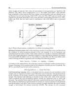
CIRCUIT SCHEMATIC
Photocell is a resistor whose resistance varies with light. In
dark, it has resistance of about 10Mohms. In bright light,
it has a resistance of about 100 ohms.
Circuit is a voltage divider. When photocell is in dark, resistance
is high, and signal output is high (near 0v). In light, photocell
resistance is low, and signal output is low (near 0v).
Photocell is an analog sensor. Plug into an Analog Input.
+5v
gnd
Connector Plug
+5v
ground
signal
DO NOT SOLDER TO PHOTOCELL!!
330 ohm
white wire
blue wire
signal out
ground
+5v
green wire
violet wire
Plug into
Analog Input.
TRW
OPB-5447
infrared reflection
sensor
Phototransistor
IR Receiver
Infrared
Emitter
B
E
C
+5v
GND
330
ohm
(white)
(blue)
47K
(on main board)
(violet)
(green)
EQUIVALENT CIRCUIT
SIGNAL
OUT
Circuit is a voltage divider. When bend
sensor is flexed, resistance is high, and
signal output is high (near 5v). Unflexed
resistance is low, and signal output is low
(near 0v).
Connector Plug
+5v
ground
signal
bend sensor
47k resistor
(on 6.270 board)
signal output
CIRCUIT SCHEMATIC
+5v
gnd
Circuit is a voltage divider. Because of
asymettry in voltage divider due to 47k
resistor on board, the sensor will perform
in one direction than the other.
Bend Sensor Assembly: silver side faces out;
plastic side faces in.
Use enough wiring!
Connector Plug
+5v
ground
signal
bend sensor
47k resistor
(on 6.270 board)
signal output
EQUIVALENT CIRCUIT
+5v
gnd
bend sensor
Sensor
Aperture
Use 12-15’’ of wire
Connect signal ground of sensor
to its case with wire
Connector Plug
+5v
ground
signal
Sharp GP1U52X
Connector Plug
+5v
ground
signal
Potentiometer
Detector
Phototransistor
IR Receiver
330 ohm
Infrared
Emitter
2 pin male connector
(plugs into LEDOUT
jack on expansion board)
B
E
C
Pin 1
Pin 3
+-
signal out
ground
+5v
Pin 2
Pin 4
Plug into
Analog Input.
TOP VIEW
12
34
Pin 1. Cathode
Pin 2. Collector
Pin 3. Anode
Pin 4. Emitter
2.2Kohm
Emitter
D
+
+
E
MOC70V
Connector Plug
+5v
ground
signal
S41
907
Do not overheat when soldering
to sensor leads!
Motor power contacts
Motor shaft
Motor Mount Tubing
Place glue here,
on outside of tubing
8-tooth gear
attached to motor shaft
Polaroid motor 2x4 LEGO plate
glued to motor
Gear center perfectly
aligned with LEGO hole
24 24
Polaroid motor
LEGO Jig, side view
LEGO Jig, rear view
Power (red)
Ground (black or brown)
Signal
Power
Ground
Plugs into Servo Motor
Plugs into 6.270 Board
Port D2
PWR OUT+
PWR OUT-
Use 12 inches wire.
Polarizing diode
(1N4001 or equiv.)