McGraw-Hill- PDA Robotics - Using Your PDA to Control Your Robot 1 Part 4 ppsx
Bạn đang xem bản rút gọn của tài liệu. Xem và tải ngay bản đầy đủ của tài liệu tại đây (549.85 KB, 20 trang )
PDA Robotics
from the time its LED finishes transmitting to the time its receiver
diode is capable of receiving, the remote station must wait 1 ms from
receiving the last bit of a frame before beginning to transmit a new
frame. The remote station performs this wait to honor the local transceiver’s turnaround time.
To honor the turnaround time of the remote transceiver, the IrLAP protocol might sometimes specify to delay transmission of a packet. To do
so, the IrLAP protocol specifies the amount of time before a packet
should be transmitted. The IrDA miniport driver must not transmit the
packet before waiting the requested amount of time, although the driver can wait longer if necessary. The IrLAP protocol specifies transmission delay time of a packet in the media-specific member of the packet’s associated out-of-band (OOB) data block.
IrLAP defines the format of the frames sent and received on the IR
media. Each IrLAP frame consists of the following elements:
•
One or more beginning of frame (BOF) flags that mark the beginning of the frame. The size of the BOF member varies in length,
depending on the speed.
•
An address (A) member that identifies the secondary connection
address. The address member is 8 b. The address member specifies the address of a device that belongs to a particular IrDA miniport driver. This IrDA miniport driver transmits or receives the
frame that contains this address through this device.
•
A control (C) member that specifies the function of the particular
frame. The control member is 8 b.
•
An optional information (I) member that contains the information data. The information member is an integral number of
octets.
•
A frame check sequence (FCS) member that allows the receiving
station to check the transmission accuracy of the frame. The FCS
member is either 16 or 32 b, depending on the speed.
•
An end of frame (EOF) flag that signals the end of the frame. The
size of the EOF member varies, depending on the speed.
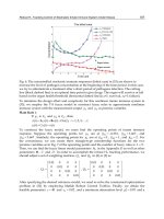
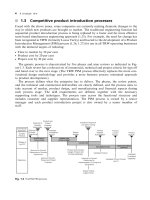
The following example of an IrLAP frame shows the order of the elements that were described in the preceding section.
38
Chapter 4 / Infrared Communications Overview
BOF
A
C
I
FCS
EOF
SIR Coding
This topic describes how IrDA miniport drivers or their IR NICs code
frames for transmission at Serial IrDA (SIR) link speeds. The SIR specification defines a short-range IR asynchronous serial transmission
mode with one start bit, eight data bits, and one stop bit. The maximum data rate is 115.2 Kb/s (half duplex). This SIR coding scheme is
called return to zero, inverted (RZI). The primary benefit of coding
frames for SIR speeds is that existing serial hardware can be used very
cheaply. The low cost of using serial hardware is one of the reasons for
the widespread availability of IR SIR devices.
The BOF flag for SIR speeds is defined as 0xC0. The EOF value is
defined as 0xC1. To avoid ambiguity in a frame that contains BOF and
EOF, an escape sequence is defined for values of 0xC0 and 0xC1 that
occur in other parts of the frame. The escape character is defined as
0x7D.
For each byte that the transmitter encounters that is the same as a BOF,
EOF, or the escape character, the transmitter performs the following
steps:
1. Inserts a control-escape byte (0x7D) preceding such a byte.
2. Complements bit five of each byte that is the same as the BOF,
EOF, or escape character (i.e., performs an exclusive OR operation on such a byte with 0x20).
MIR Coding
This topic describes how IrDA miniport drivers and their IR NICs code
frames for transmission at Medium IrDA (MIR) link speeds. The MIR
data rates are 0.576 Mb/s and 1.152 Mb/s (half duplex).
For MIR link speeds, definitions for BOF and EOF values are the same;
both BOF and EOF are defined as 0x7E. To avoid ambiguity in the
frame with BOF and EOF, rather than using an escape sequence as is
done at SIR rates, a zero is inserted at MIR rates after any five consecutive one bits in all members, except BOF and EOF. Because the
process of inserting and stripping zeros at the bit level is highly
39
PDA Robotics
processor-intensive, it is strongly recommended that this logic be
implemented in hardware. At MIR link speeds, two BOF flags are
required on every frame.
For MIR link speeds, the CRC used is the same as for SIR speeds. That
is, for MIR link speeds, the IrDA miniport driver also typically calculates the CRC value, rather than the driver’s hardware.
FIR Coding
This topic describes how IrDA miniport drivers and their IR NICs code
frames for transmission at Fast IrDA (FIR) link speeds. The FIR specification defines short-range, low-power operation at 4 Mb/s (half
duplex). All FIR devices are also required to support SIR operation.
For FIR link speeds, an entirely different coding scheme, called four
pulse position modulation (4PPM), is used. The 4PPM coding scheme
defines special flags for BOF and EOF. Always implement the 4PPM
coding scheme in hardware.
The IrDA miniport driver may still be required to calculate the CRC to
validate the frame. For FIR link speeds, a 32-bit CRC is used. An algorithm for calculating the 32-bit CRC is available in the publication
Infrared Data Association Serial Infrared Physical Layer Link
Specification, available from IrDA.
VFIR Coding
This topic describes how IrDA miniport drivers and their IR NICs code
frames for transmission at Very Fast IrDA (VFIR) link speeds. The
VFIR specification defines short-range, low-power operation at 16
Mb/s (half duplex). All VFIR devices are also required to support FIR
and SIR operation.
For VFIR link speeds, an entirely different coding scheme, called
HHH(1,13), is used. The letters HHH that represent this coding scheme
are the initials of the three researchers who invented it. Always implement the HHH(1,13) coding scheme in hardware. For more information on HHH(1,13), see the publication Infrared Data Association
Serial Infrared Physical Layer Link Specification, available from IrDA.
The IrDA miniport driver’s hardware can calculate the CRC to validate
the frame. However, if hardware does not calculate CRC, the IrDA
40
Chapter 4 / Infrared Communications Overview
miniport driver must calculate CRC. For VFIR link speeds, a 32-bit
CRC is used, which is the same as that used for FIR link speeds. An
algorithm for calculating the 32-bit CRC is available in the publication
Infrared Data Association Serial Infrared Physical Layer Link
Specification.
The IrDA specification will give you an idea of the technical details
involved in the protocol. When we write to the software, you will find
it is not as complicated as it seems. The creators of the Windows and
Palm operating systems gave an application programming interface
(API) that makes creating an association, sending, and receiving data
a fairly straightforward task.
41
This page intentionally left blank.
5
The
Electronics
This chapter consists of two parts. First is an overview of the electronic design, focusing on various portions of the schematic diagram.
Second is a description of each component, including its function and
how it interacts with the others. The next chapter will explain step-bystep how to create the circuit, from “burring the board” to soldering
each component.
System Overview
The circuit consists of three parts that can be separated, as I have with
this project, or kept together. The main board is connected to the
infrared (IR) transceiver and the motor controller circuit via 6-wire ribbon connectors. I chose to do this so that the motor circuit and the
transponder could be placed anywhere, allowing for flexibility of
design. The artwork for the circuit in Figure 5.1 shows the three components of the circuit.
Figure 5.2 shows the topside of the boards (with the top personal digital assistant (PDA) support plate removed) and how they have been
positioned on PDA Robot.
Not all PDAs have the IR port in the same position, so the ribbon connector lets you position the PDA in any direction. You can easily cut
43
Copyright 2003 by The McGraw-Hill Companies, Inc. Click Here for Terms of Use.
PDA Robotics
Figure 5.1
The circuit layout: Main board, motor controller, and the infrared transceiver (only one is
needed).
Figure 5.2
The main board (A),
infrared transceiver
(B), and the motor
controller (C)
mounted to the
bottom plate.
44
Chapter 5 / The Electronics
Figure 5.3
IPAQ and Visor
PDAs.
a slot on the top plate and stand the PDA vertically. Figure 5.3 shows
an iPAQ and a Visor positioned next to the transceiver.
For this project, I used the MG Chemical process to create the circuit
board. Protel 98 SE was used to create the schematic diagrams and
printed circuit board (PCB) artwork used in the MG chemical process.
Figure 5.4 shows the main portion of the circuit board after it was
Figure 5.4
The main circuit
after exposure and
etching.
45
PDA Robotics
Figure 5.5
Schematic diagram of the main circuit board.
exposed and etched. It is being drilled in preparation for placement of
the components. Figure 5.5 shows the schematic diagram of the main
circuit board.
Setting the Baud Rate
The MCP2150 baud rate lines, pins 1 and 18, are connected to the 8pin duel in-line packet (DIP) switch. Pins 5 and 7 are connected to
ground (low), and pins 6 and 8 are high (ϩ5 V). This allows us to set
the baud rate that the MCP2150 communicates with PIC169876. It is
interesting to note that the baud rate at which the MCP2150 communicates with the PDA through the IR transceiver is independent of this
setting (see Figure 5.6). The actual IR baud rate is determined during
the handshake phase of the Infrared Data Association (IrDA) negotiation and is transparent to users. The only parameter users can set is
the maximum baud rate that can be negotiated (this is explained in the
software chapters for the Palm OS and Windows handhelds).
Table 5.1 shows the DIP switch settings and the associated baud rates.
46
Chapter 5 / The Electronics
Figure 5.6
Portion of
MCP2150 showing
baud rate lines
connected to DIP
switch.
Table 5.1
DIP Switch Settings and Associated Baud Rates
DIP Switch 1
(Baud 0)
DIP Switch 2
(Baud 0)
DIP Switch 3
(Baud 1)
DIP Switch 4
(Baud 1)
Baud Rate at
11.0592 MHz
Off
On
Off
On
On
Off
On
Off
Off
Off
On
On
On
On
Off
Off
9600
19200
57600
115200
Figure 5.7 shows a close-up of the DIP switches with the baud of the
MCP2150 set to 115200.
The MCP2150 Connection to the IR Transceiver
The IR transponder used by PDA Robot consists of a Microchip
MCP2150 IrDA standard protocol stack controller and a Vishay
TFDS4500 serial IR transceiver (a TFDU6102 fast IR transceiver can be
used as well). The transceiver contains the IR emitter and receiver and
the MCP2150 handles the IrDA handshaking and data exchange
between the Robot and the PDA.
47
PDA Robotics
Figure 5.7
PDA Robot with the
baud rate set to
115200.
The components required for the Vishay TFDS4500 transceiver are
located on the main board circuit, and the actual transceiver itself is
connected via the ribbon cable. Figure 5.8 shows the schematic diagram connection of the MCP2150’s IR output (pin 2: TXIR) and input
pins (pin 3: RXIR) connected to the ribbon cable connector.
The IR transceiver schematic shows the pins of the transceiver tied to
the appropriate connector pins that line up with those on the main
board. Figures 5.9 and 5.10 illustrate this.
Figure 5.8
Schematic diagram showing MCP2150 connections to the IR transceiver.
48
Chapter 5 / The Electronics
Figure 5.9
IR transceiver schematic.
The MCP2150 Connection to the PIC16F876
Microcontroller
The microcontroller is connected to the MCP2150 IrDA protocol stack
decoder via the microcontroller’s configurable B port. The block diagram in Figure 5.11 shows the relationship between the transceiver,
the controller, and the MCP2150.
The schematic diagram in Figure 5.12 shows the actual pin connections between the PIC16F876 and the MCP2150. RBO is configured as
Figure 5.10
MCP2150 (A), the
ribbon connection
(B), and the
transceiver (C).
49
PDA Robotics
Figure 5.11
The PIC16F876, MCP2150, and TFDS4500 block diagram.
the RS232 transmit pin and RB1 as the receive pin. Pins RB6 and RB7
are configured as inputs, used to monitor the MCP2150’s Request to
send (RTS: pin 13) and Clear to send (CTS: pin 12) pins. RB2, RB3,
RB4, and RB5 are configured as digital outputs used to switch the
L298 motor controller.
Figure 5.12
Schematic of PIC16F876 connection to MCP2150.
50
Chapter 5 / The Electronics
The Motor Controller Circuit
The motor controller circuit is connected to the main board through a
six-wire ribbon connector, and has an independent load (separate from
the logic) used to power the motors and the IR range finder. The power
and ground for the L298’s logic is carried from the main board through
the ribbon cable, along with the data lines. The L298 requires that the
grounds for the logic and the load must be common, so powering the
logic from the regulated supply of the main board works out well.
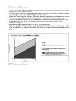
Figure 5.13 shows the schematic diagram of the motor controller portion of the circuit. Figure 5.14 shows the physical layout of the motor
controller and the ribbon cable that connects it to the main board.
Figure 5.13
Motor controller schematic diagram.
51
PDA Robotics
Figure 5.14
Motor controller
PCB motor 1
connector (A),
ribbon connector
(B), motor 2
connector (C),
motor power supply
connector (D), range
finder power
connection (E),
L298 motor
controller chip (F),
and diode (G).
The Sharp GPD12 IR Range Finder
The Sharp GPD12 IR range finder is connected to the first configurable
analog pin on the PIC16F876. Figure 5.15 shows the pin (C), which is
connected to the analog output of the range finder and the analog
input of the microchip.
Figure 5.15
Left side of main
circuit, (A) 9 V
power connector,
(B) resistor, (C)
range finder input
pin, (D) capacitor,
(E) 20.0000 MHz
crystal oscillator, (F)
+5 voltage
regulator, (G)
16F876 microcontroller, (H) and
motor controller
ribbon connector.
52
Chapter 5 / The Electronics
Component Descriptions
The Vishay TFDS4500
The TFDU4100, TFDS4500, and TFDT4500 are a family of low-power
IR transceiver modules compliant to the IrDA standard for serial
infrared (SIR) data communication, supporting IrDA speeds up to
115.2 kb/s. Integrated within the transceiver modules is a photo PIN
diode, infrared emitter (IRED), and a low-power analog control integrated circuit (IC) to provide a total front-end solution in a single package. Telefunken’s SIR transceivers are available in three package
options, including our Baby Face package (TFDU4100), once the
smallest SIR transceiver available on the market. This wide selection
provides flexibility for a variety of applications and space constraints.
The transceivers are capable of directly interfacing with a wide variety of I/O chips, which perform the pulse-width modulation/demodulation function, including Telefunken’s TOIM4232 and TOIM3232. At
a minimum, a current-limiting resistor in series with the IR and a VCC
bypass capacitor are the only external components required to implement a complete solution, as is the case with PDA Robot.
TFDS4500 Features:
•
Compliant to the latest IrDA physical layer standard (up to 115.2
kb/s).
•
2.7 to 5.5 V wide operating voltage range.
•
Low power consumption (1.3 mA supply current).
•
Power sleep mode through VCC1/SD pin (5 nA sleep current).
•
Long range (up to 3.0 m at 115.2 kb/s).
•
Three surface-mount package options—universal (9.7 ϫ 4.7 ϫ
4.0 mm), side view (13.0 ϫ 5.95 ϫ 5.3 mm), top view (13.0 ϫ 7.6
ϫ 5.95 mm).
•
Directly interfaces with various super I/O and controller devices.
•
Built-in electromagnetic interference (EMI) protection—no external shielding necessary.
•
Few external components required.
•
Backward compatible to all Telefunken SIR IR transceivers.
53
PDA Robotics
Figure 5.16
Transceiver package options.
Figure 5.16 shows the three packages available. PDA Robot is using
the side mount package (TFDS).
The transceiver conveniently contains an amplifier, comparator, drivers,
ACG logic, the IRED, and receiver, as seen Figure 7.17.
Figure 5.18 shows the recommended circuit to use with the transceiver. The outlined components described as optional have been included in the design of PDA Robot. The capacitor is used to clean up any
noise normally caused by the power supply. The noise being suppressed comes mostly from the two DC motors used in this project.
The capacitors on the motor control circuit and those tied to the
MCP2150 and TFDS4500 are used for logic circuit noise suppression.
The only required components for designing an IrDA 1.2 compatible
design using Telefunken SIR transceivers are a current limiting resis-
Figure 5.17
Transceiver block diagram.
54
Chapter 5 / The Electronics
Figure 5.18
Recommended circuit diagram.
tor to the IRED. However, depending on the entire system design and
board layout, additional components may be required. It is recommended that the capacitors C1 and C2 be positioned as near as possible to the transceiver power supply pins. A tantalum capacitor should
be used for C1, while a ceramic capacitor should be used for C2 to suppress radio frequency (RF) noise. Also, when connecting the described
circuit to the power supply, use low impedance wiring.
R1 is used for controlling the current through the IRED. To increase
the output power of the IRED, reduce the value of the resistor.
Similarly, to reduce the output power of the IRED, increase the value
of the resistor. For typical values of R1, see Figure 5.19. For example,
for IrDA-compliant operation (VCC2 ϭ 5 V Ϯ 5%), a current control
resistor of 14 ohms is recommended. The upper drive current limitation is dependent on the duty cycle, and is given by the absolute maximum ratings on the data sheet and the eye safety limitations given by
IEC825–1. R2, C1 and C2 are optional and dependent on the quality of
the supply voltage VCC1 and injected noise. An unstable power supply with dropping voltage during transmission may reduce sensitivity
(and transmission range) of the transceiver.
55
PDA Robotics
Figure 5.19
Physical dimensions of the side view package used in PDA Robot.
The sensitivity control (SC) pin allows the minimum detection irradiance
threshold of the transceiver to be lowered when set to a logic HIGH.
Lowering the irradiance threshold increases the sensitivity to IR signals
and increases transmission range up to 3 m. However, setting the Pin SC
to logic HIGH also makes the transceiver more susceptible to transmission
errors, due to an increased sensitivity to fluorescent light disturbances.
It is recommended that the pin SC be set to logic LOW or left open, if
the increased range is not required or if the system will be operating
in bright ambient light.
56
Chapter 5 / The Electronics
This SC pin has been driven LOW in the PDA Robot circuit. However,
if you decide to modify the circuit, I recommend putting a switch on the
board or tying this line to a pin on the microcontroller. This would
allow you to set SC high or low physically through the switch or programmatically through the microcontroller. This would enable you to
hold the PDA at a much further distance from the craft when testing and
calibrating the system. You could also use the PDA as a remote control.
The guide pins on the side-view and top-view packages are internally
connected to ground, but should not be connected to the system
ground, to avoid ground loops. They should be used for mechanical
purposes only and should be left floating.
PDA Robot does not ground the guide pins. They are used only to help
secure the unit to the PCB.
Shutdown. The internal switch for the IRED in Telefunken SIR transceivers is designed to be operated like an open collector driver. Thus,
the VCC2 source can be an unregulated power supply, while only a
well-regulated power source with a supply current of 1.3 mA connected to VCC1/SD is needed to provide power to the remainder of the
transceiver circuitry in receive mode. In transmit mode, this current is
slightly higher (approximately 4 mA average at 3 V supply current),
and the voltage is not required to be kept as stable as in receive mode.
A voltage drop of VCC1 is acceptable down to about 2.0 V when
buffering the voltage directly from the pin VCC1 to GND; see Figure
5.20a. This configuration minimizes the influence of high-current
surges from the IRED on the internal analog control circuitry of the
transceiver and the application circuit. Also, board space and cost savings can be achieved by eliminating the additional linear regulator
normally needed for the IRED’s high current requirements.
The transceiver can be very efficiently shut down by keeping the IRED
connected to the power supply VCC2, but switching off VCC1/SD. The
power source to VCC1/SD can be provided directly from a microcontroller. In shutdown, current loss is realized only as leakage current
through the current-limiting resistor to the IRED (typically 5 nA). The
settling time after switching VCC1/SD on again is approximately 50
µs. Telefunken’s TOIM3232 interface circuit is designed for this shutdown feature. The VCC_SD, S0, or S1 outputs on the TOIM3232 can
be used to power the transceiver with the necessary supply current. If
57