McGraw-Hill- PDA Robotics - Using Your PDA to Control Your Robot 1 Part 9 ppt
Bạn đang xem bản rút gọn của tài liệu. Xem và tải ngay bản đầy đủ của tài liệu tại đây (416.1 KB, 20 trang )
mnemonics and the Parallax “8051” style mnemonics. For this project,
I am using the PICmicro MCU C Compiler. It can also be used with
MPASM, a BASIC compiler, or a number of other C compilers.
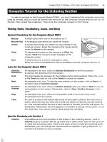
The EPIC Plus Programmer can be powered with two 9-volt batteries
or an optional AC adapter (recommended). The EPIC Plus Programmer
connects to a PC compatible parallel printer port and includes an
assembler and programming software. It is available either assembled
or as a bare board.
Software Installation
The EPIC Plus Programmer files are compressed into a self-extracting
file on the disk. They must be uncompressed before use. To uncom-
PDA Robotics
138
Figure 7.1
The EPIC Plus
microcontroller
programmer with
zoomed in ZIF
socket.
PDA 07 5/27/03 8:44 AM Page 138
press the files, first create a directory on your hard drive called EPIC,
or another name of your choosing by typing:
c:\
md epic
at the DOS prompt.
Change to this directory:
cd epic
Assuming the distribution diskette is in drive a:, uncompress the files
into the EPIC subdirectory:
a:\epic2xx -d
where epic2xx is the name of the self-extracting file on the diskette.
Don’t forget the -d option on the end of the command. This ensures
that the proper subdirectories within EPIC are created. Alternatively,
INSTALL.BAT can be run to perform similar steps. If the EPIC direc-
tory already exists, you will get an error message and the installation
will continue.
Hardware Installation
Make sure there are no PICmicro MCUs installed in the EPIC pro-
gramming socket or any connected adapter’s socket until the program-
ming software is executed and the light-emitting diode (LED) is off.
Also, be sure that the EPIC Plus Programmer is placed on an insulat-
ed surface to prevent the shorting out of traces on the bottom.
Connect the EPIC Plus Programmer to a PC compatible parallel printer
port using a 25-pin male to 25-pin female printer extension cable. The
EPIC Plus Programmer uses pins 2–6, 10, and 19–25. A serial cable may
not have all of the necessary connections, so be sure to use a printer exten-
sion cable. A suitable cable is available from Micro-Engineering Labs.
Make sure the programmer is connected to a parallel printer port.
Connection to a serial port or SCSI port that has similar connectors
may result in damage to the port or to the programmer. If you are pow-
ering the EPIC Plus Programmer with the optional AC adapter, plug it
into the power connector on the programmer and then into a wall out-
let. The AC adapter should provide approximately 16VDC at 500ma.
Chapter 7 / Programming the PIC16F876 Microcontroller
139
PDA 07 5/27/03 8:44 AM Page 139
When an AC is used adapter to power the programmer, the state of the
“Batt ON” jumper does not matter.
If you are powering the EPIC Plus Programmer with two 9-volt batter-
ies, plug each battery onto the battery snaps. Connect the 2-pin short-
ing jumper to the 2-pin “Batt ON” posts. It is a good idea to check the
battery voltage from time to time or if there seems to be difficulty pro-
gramming parts.
Warning: Do not connect a battery across the center snaps. Doing so
shorts out the battery and may cause it to explode.
Note: The LED may be lit at this point. It should go out when the EPIC
programming software is run. Do not insert or remove a PICmicro
MCU when the LED is on.
The EPIC Plus Programmer should now be powered up and ready to
program PICmicro MCUs.
General Operation
The next task is simply to write your program using any text editor, such
as DOS Edit or Windows Notepad, and assemble it using the assembler,
PM, included on the disk, or MPASM (or MPLAB), available from
Microchip. Instructions for the use of PM are on the included disk.
Note: For PDA Robot, I am using the PICmicro MCU compiler. The
source code and the process of generating the .HEX file is explained in
detail in the next section of this chapter.
Once your program assembles properly, the generated .HEX file may
be programmed into a PICmicro MCU using the EPIC programming
software. Three versions of the EPIC software are included: two ver-
sions for DOS (one command line and one graphical) and one for
Windows 95/98/ME/NT/2000/XP. If you choose the graphical DOS
version, it should be used in a straight DOS session or from a full-
screen DOS window in Windows 95/98 or OS/2. (Running the graph-
ical DOS version of EPIC under Windows is discouraged. Windows
[all varieties] alters the system timing and plays with the ports when
you are not looking, which may cause programming errors.)
The Windows 95/98/ME/NT/2000/XP version should, of course, be
run under Windows 95, 98, ME, NT, 2000, or XP. The Windows and
PDA Robotics
140
PDA 07 5/27/03 8:44 AM Page 140
command line DOS versions are more up to date than the graphical
DOS version, and are able to program more types of PICmicro MCUs.
EPIC for DOS
Start the DOS version of the EPIC software by typing “epicdos” at the
DOS command prompt in the directory you created previously. The
EPIC software will look around to find where the EPIC Plus
Programmer is attached, and get it ready to program a PICmicro MCU.
If the EPIC Programmer is not found, check all of the above connec-
tions and verify that no PICmicro MCU is installed in the programmer
or any connected adapter.
Once the programming screen is displayed, select the device type you
wish to program. For PIC16C8x or PIC16F8x parts, select 8x. For the
PIC14C000, PIC16C55x, 6x, 7x, or 9x parts, select 6x/7x/9x. For
PIC12C5xx parts, select 12C50x.
Enter “Alt-O” (or click “Open” with the mouse) to open your assem-
bled object (.HEX) file. Double-click on the appropriate file to load it.
Once the file has been loaded, make sure the proper device character-
istics are selected. See the Microchip data books for information on
device configuration.
Caution: Be sure that Code Protect is set to OFF before programming a
windowed (JW) PICmicro MCU. You may not be able to erase a win-
dowed part that has been code protected.
Insert a PICmicro MCU into the EPIC Plus Programmer or connected
adapter socket. The end of the PICmicro MCU with the notch should
be all the way at the Pin 1 end of the socket, away from the battery
connectors. Press “Alt-P” (or click “Program” with the mouse) to pro-
gram the PICmicro MCU.
Before programming, the EPIC software does a blank check to ensure
that the part is erased. PIC12Cxxx parts are not completely blank from
the factory. They contain a calibration value in the last location. Simply
tell EPIC that it is OK to program them anyway, when it finds they are
not blank. If the PICmicro MCU is a 16F84 or another EEPROM or flash
part, it is usually not necessary to erase it before programming.
Typing “epicdos /?” at the DOS command prompt will display a list of
available options for the EPIC software.
Chapter 7 / Programming the PIC16F876 Microcontroller
141
PDA 07 5/27/03 8:44 AM Page 141
EPIC for Windows 95/98/ME/NT/2000/XP
Because the Windows version is the simplest and most up-to-date ver-
sion, I will explain how to program the PIC16F876 using it.
Start the Windows 95/98/ME/NT/2000/XP version of the EPIC soft-
ware by navigating to the EPIC directory using Explorer and double-
clicking on EPICWin. Alternatively, you can create a shortcut to EPIC
on your desktop and double-click it. The EPIC software will look
around to find where the EPIC Plus Programmer is attached and get it
ready to program a PICmicro MCU. If the EPIC Programmer is not
found, check all of the above connections and verify there is not a
PICmicro MCU installed in the programmer or any connected adapter.
The file EPIC.INI must be in the same directory EPICWIN.EXE resides
in, and the EPIC directory should be in your path so that Windows can
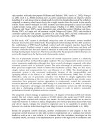
find the device drivers. Once the programming bar is displayed, select
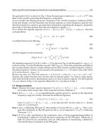
the device type you wish to program. Figure 7.2 shows the main win-
dow with the 16F876 device selected as the target.
Click the Open button or File/Open with the mouse to open your
assembled object (.HEX) file. Double-click on the appropriate file to
load it. Once the file has been loaded, make sure the proper device
characteristics are selected under the Options menu. See the
Microchip data books for information on device configuration.
Caution: Be sure that Code Protect is set to OFF before programming a
windowed (JW) PICmicro MCU. You may not be able to erase a win-
dowed part that has been code protected.
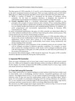
For the PIC16F876 and the crystal oscillator used with PDA Robot,
ensure that the crystal is set to High Speed (HS) and enable the Power-
up timer and Brown-out reset under the Configuration menu. Use the
default values for everything else in the configuration menu. Figure
7.3 shows the settings required.
PDA Robotics
142
Figure 7.2
EPICWin main window.
PDA 07 5/27/03 8:44 AM Page 142
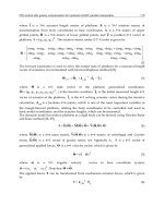
The Options I like to have set to ensure that everything works correct-
ly are Program/Verify Code, Program/Verify Configuration, Program/
Verify Data, Reread File Before Programming, Erase Before
Programming, and Verify After Programming. Even though it is not
necessary to erase the 16F876 before programming, I like to ensure
that it is because I have had the odd problem when I don’t erase it.
Figure 7.4 shows the Options menu.
Chapter 7 / Programming the PIC16F876 Microcontroller
143
Figure 7.3
PIC16F876
configuration
options.
Figure 7.4
PIC programming
options.
PDA 07 5/27/03 8:44 AM Page 143
Insert a PICmicro MCU into the EPIC Plus Programmer or connected
adapter socket. The end of the PICmicro MCU with the notch should
be all the way at the Pin 1 end of the socket, away from the battery
connectors. Click the Program button or Run/Program with the mouse
to program the PICmicro MCU.
Before programming, the EPIC software does a blank check to ensure
that the part is erased. If the PICmicro MCU is a 16F84 or another EEP-
ROM or flash part, it is usually not necessary to erase it before pro-
gramming. PIC16F7x and PIC18Fxxx devices do require erasing each
time before the MCU may be reprogrammed.
The current setup is saved to the file EPICCFG.INI when you exit
EPICWin. It is reloaded the next time EPICWin is started.
EPICWin Controls
The Open speed button opens a .HEX file for programming. The name
of an open file appears in the EPICWin title bar. Previous configura-
tion information will not be altered if Options/Update Configuration
is not checked.
The Save speed button will save the current code, data, ID, and con-
figuration information to the currently open file. If no file has been
previously selected, it will prompt for a filename.
The Program speed button will program the current code, data, ID, and
configuration into the selected device. It will optionally load the lat-
est version of the .HEX file before programming. The device will be
checked to ensure it is blank before programming, unless
Options/Skip Blank Check is checked.
The Verify speed button will compare the current code, data, ID,
and configuration to the programmed device. If the information
does not match, an error message is displayed. A verify is also done
as the device is being programmed. A code protected device cannot
be verified.
The Read speed button will read the current code, data, ID, and con-
figuration from the selected device. The configuration information
will not be read if Options/Update Configuration is not checked.
The Blank Check speed button will read the code space to ensure a
device is blank. It will not check the data space, ID, configuration, or
PDA Robotics
144
PDA 07 5/27/03 8:44 AM Page 144
the oscillator calibration word programmed by the factory into some
devices.
The Erase speed button will erase EEPROM or flash electrically erasa-
ble devices. It is grayed out for devices that cannot be electrically
erased.
The Device box allows selection of the device to be programmed. Click
the down arrow to the right of the box to drop down a list of support-
ed devices, then click on the device. This device information, includ-
ing the default device that is selected on start-up, is contained in the
file EPIC.INI. This file must be in the same directory as EPICWIN.EXE.
Select the device before a .HEX file is opened to ensure the configura-
tion information is properly interpreted. Devices with parentheses
after them indicate that they will program either the base version of
the part, or the version contained within the parentheses. For exam-
ple, selecting the device listed as PIC16F84(A) means that either the
PIC16F84 or the PIC16F84A may be programmed.
All of the speed buttons, along with other settings, are also available
using the drop-down menus.
The PICmicro MCU Compiler
The code for PIC16F876 used in PDA Robot was compiled using the
PICmicro MCU compiler. The code is written in C, and will be
explained in detail in this chapter.
The PCM compiler is for 14-bit opcodes, and PCH is for the 16- and
18-bit PICmicro MCU. This compiler is specially designed to meet the
special needs of the PICmicro MCU controllers. These tools allow
developers to quickly design application software for these controllers
in a highly readable high-level language.
The compilers have some limitations when compared to a more tradi-
tional C compiler. The hardware limitations make many traditional C
compilers ineffective. As an example of the limitations, the compilers
will not permit pointers to constant arrays. This is due to the separate
code/data segments in the PICmicro MCU hardware and the inability
to treat ROM areas as data. On the other hand, the compilers have
knowledge about the hardware limitations and do the work of decid-
ing how to best implement your algorithms. The compilers can imple-
Chapter 7 / Programming the PIC16F876 Microcontroller
145
PDA 07 5/27/03 8:44 AM Page 145
ment very efficiently normal C constructs, as well as input/output
operations and bit twiddling operations.
The Command Line Compiler
The command line compiler is invoked with the following command:
CCSC options cfilename
Valid options:
+FB Select PCB (12-bit). -D Do not create debug file.
+FM Select PCM (14-bit). +DS Standard .COD format debug file.
+FH Select PCH (PIC18XXX). +DM .MAP format debug file.
+F7 Select PC7 (PIC17XXX). +DC Expanded .COD format debug file.
+FS Select PCS (SX). +Yx Optimization level x (0-9).
+ES Standard error file. +T Create call tree (.TRE).
+EO Old error file format. +A Create stats file (.STA).
-J Do not create PJT file. -M Do not create symbol file.
The xxx in the following is optional. If included it sets the file extension:
+LNxxx Normal list file. +O8xxx 8-bit Intel HEX output file.
+LSxxx MPASM format list file. +OWxxx 16-bit Intel HEX output file.
+LOxxx Old MPASM list file. +OBxxx Binary output file.
+LYxxx Symbolic list file. -O Do not create object file.
-L Do not create list file.
+P Keep compile status window up after compile.
+Pxx Keep status window up for xx seconds after compile.
+PN Keep status window up only if there are no errors.
+PE Keep status window up only if there are errors.
+Z Keep scratch and debug files on disk after compile.
I=" " Set include director y search path, for example:
I="c:\picc\examples;c:\picc\myincludes"If no I= appears on the command
line the .PJT file will be used to supply the include file paths.
#xxx="yyy" Set a global #define for id xxx with a value of yyy, example:#debug="true"
+STDOUT Outputs errors to STDOUT (for use with third-party editors).
+SETUP Install CCSC into MPLAB (no compile is done).
+V Show compiler version (no compile is done).
+Q Show all valid devices in database (no compile is done).
If @filename appears on the CCSC command line command line,
options will be read from the specified file. Parameters may appear on
multiple lines in the file.
PDA Robotics
146
PDA 07 5/27/03 8:44 AM Page 146
If the file CCSC.INI exists in the same directory as CCSC.EXE, then
command line parameters are read from that file before they are
processed on the command line. For example, to compile the source
code and generate a .HEX file for PDA Robo, we would type the fol-
lowing from the PICC directory.
CCSC +FM +P C:\PROGRA~1\PICC\PDABOT.C
The Source Code
This section explains in detail the C language constructs used in the
source code of the program running on the PIC16F876. I have
offloaded most of the processing to the PDA so the code on the micro-
controller is very straightforward. To quote Albert Einstein, “Make
things as simple as possible, but not simpler.” The software waits for
a command from the PDA, signaling each motor to rotate forward,
reverse, or stop and a command prompting PDA Robot to send the
range data to the PDA. For example, the PDA can instruct the craft to
turn by sending two commands, a “motor 1 forward” command and a
“motor 2 reverse” command. This section describes an optimization to
the code and includes the HEX listing that can be copied to a file and
burned to the PIC16F876.
The following is the code listing for pdabot.c.
// PDABOT.C
//
// Software for the PIC16F876 used to controlPDA Robot
//
// Author: Douglas H Williams
// PDA Robotics: McGraw-Hill 2003
//
#include <16f876.h>
//
// We are using a 20 MHz oscillator so set the clock accordingly
//
#use delay(clock=20000000)
//
// Set pins B0 & B1 as our RS232 por t which are connected to the
// MCP2150 IrDA Protocol Stack Controller
//
#use rs232(baud=115200, xmit=PIN_B1, rcv=PIN_B0, stream=PDA)
Chapter 7 / Programming the PIC16F876 Microcontroller
147
PDA 07 5/27/03 8:44 AM Page 147
main() {
//
// The value from the range finder
//
int range_value;
//
// The command sent from the PDA
//
char cmd;
//
// Set up port A as analog, pin A0 is connected
// to the sharp GP2D12 infrared range finder
//
setup_port_a( ALL_ANALOG );
setup_adc( ADC_CLOCK_INTERNAL );
set_adc_channel( 0 );
//
// Set the B port pins that interface to the
// L298 motor controller low to ensure no
// motor movement on startup. Pins B2 & B3
// control Motor 1 and B4 & B5 control Motor 2.
//
output_low(PIN_B2);
output_low(PIN_B3);
output_low(PIN_B4);
output_low(PIN_B5);
output_low(PIN_B6);
output_low(PIN_B7);
delay_cycles(3);
//
// Let the PDA know we are alive by sending some data (A space characater)
//
fprintf(PDA, " ");
//
// Loop indefinitely handling commands from the PDA
//
while (1){
//
PDA Robotics
148
PDA 07 5/27/03 8:44 AM Page 148
// Get the command sent from the PDA
//
cmd = fgetc(PDA);
//
// Motor 1 commands
//
//
// Motor 1 For ward
//
if( cmd == 'a')
{
output_high(PIN_B2);
output_low(PIN_B3);
}
//
// Motor 1 Reverse
//
if( cmd == 'b')
{
output_low(PIN_B2);
output_high(PIN_B3);
}
//
// Motor 1 Stop
//
if( cmd == 'c')
{
output_low(PIN_B2);
output_low(PIN_B3);
}
//
// Motor 2 For ward
//
if( cmd == 'd')
{
output_high(PIN_B4);
output_low(PIN_B5);
}
//
// Motor 2 Reverse
//
Chapter 7 / Programming the PIC16F876 Microcontroller
149
PDA 07 5/27/03 8:44 AM Page 149
if( cmd == 'e')
{
output_low(PIN_B4);
output_high(PIN_B5);
}
//
// Motor 2 Stop
//
if( cmd == 'f')
{
output_low(PIN_B4);
output_low(PIN_B5);
}
//
// The PDA has requested that we get the value from the
// Analog input of the Range Finder
//
if( cmd == 'g')
{
//
// Give some time for the clear to send. We could check the CLS
// pin from the MCP2150 here by reading the port value of Pins
// RB6 and RB7 can be configured as.inputs and used to monitor the
// MCP2150's Request to send (RTS: pin 13) and Clear to send (CTS: pin 12)
// because I have connected them on the circuit board. However, if the data is
// lost the PDA will ask for it again. See Chapter 5, Figure 5.12: Schematic of
// PIC16F876 connection to MCP2150
//
delay_ms(3);
//
// Read the analog value from the range finder
//
range_value = Read_ADC();
//
// Send the value to the PDA
//
putc(range_value);
}
}
}
PDA Robotics
150
PDA 07 5/27/03 8:44 AM Page 150
This code can be optimized by having the PDA simply send a byte that
represents the state of the pins. By doing this, we can replace the six “if”
commands used to set the pins and the state of the motor with the line:
OUTPUT_B(value);
If we convert the number to binary, you can see that we need the first
four bits, and the fifth bit can be used to represent a request for the
rangefinder data. So if the value is less than 64, we know it is a motor
command, and if higher, a request for the range.
010100 (binar y) = 20 (decimal) = Both motors moving for ward
101000 (binar y) = 40 (decimal) = Both motors moving Reverse
…
000000 (binar y) = 0 (decimal) = Both motors stopped
1000000 (binar y) = 64 decimal = The PDA has requested the range data.
The code preceding was written using Notepad and saved as pdabot.c
in c:\Program files\picc\pdabot. The next step is to invoke the com-
mand line compiler. When you use the following command in a com-
mand prompt from the picc directory, the +P flag instructs the com-
piler to leave the compilation window displayed when it is complete.
This allows you to see if any errors were detected in the code and on
what line the compiler was having the problem.
CCSC +FM +P C:\PROGRA~1\PICC\PDABOT\PDABOT.C
Figure 7.5 shows the command prompt with the CCSC command line
used to invoke the compiler and compiler the code to the .HEX file
that we will burn onto the PIC microcontroller.
The compiler displays a window, shown in Figure 7.6, indicating the
status of the compilation and information regarding the memory usage
of the device.
The following is the compiled hex listing for the above source code
that is loaded into the memory of the PIC16F876.
0000- 3000 008a 283f 0000 3008 00f7 1683 1406
0008- 1283 1806 2809 01af 17f7 281c 13f7 281c
0010- 1003 1806 1403 0caf 1777 281c 1377 0bf7
0018- 2810 082f 00f8 2829 3016 1bf7 3006 00f8
0020- 0bf8 2820 0000 0000 1bf7 280e 1b77 2816
0028- 2810 118a 120a 2862 302f 0084 0800 1903
0030- 283e 3006 00f8 01f7 0bf7 2834 0bf8 2833
0038- 307b 00f7 0bf7 283a 0b80 2831 3400 0184
Chapter 7 / Programming the PIC16F876 Microcontroller
151
PDA 07 5/27/03 8:44 AM Page 151
0040- 301f 0583 3007 1683 009f 1086 1283 1486
0048- 01a1 1683 1106 1283 1106 1683 1186 1283
0050- 1186 1683 1206 1283 1206 1683 1286 1283
0058- 1286 1683 1306 1283 1306 1683 1386 1283
0060- 1386 2804 0878 00a4 0b24 2866 1683 1106
0068- 1283 1506 3003 00af 202c 1683 1186 1283
0070- 1186 0824 3c02 1d03 2875 1683 1186 1283
0078- 1586 3003 00af 202c 1683 1106 1283 1106
0080- 0824 3c03 1d03 2884 1683 1106 1283 1106
PDA Robotics
152
Figure 7.5
Command line
compilation.
Figure 7.6
CCSC compilation
window.
PDA 07 5/27/03 8:44 AM Page 152
0088- 3003 00af 202c 1683 1186 1283 1186 0824
0090- 3c72 1d03 2893 1683 1106 1283 1506 1683
0098- 1186 1283 1186 3003 00af 202c 0824 3c0f
00a0- 1d03 28ad 1683 1206 1283 1606 1683 1286
00a8- 1283 1686 3003 00af 202c 0824 3c66 1d03
00b0- 28bc 1683 1106 1283 1106 1683 1186 1283
00b8- 1586 3003 00af 202c 0824 3c73 1d03 28c0
00c0- 1683 1106 1283 1106 1683 1186 1283 1186
00c8- 3003 00af 202c 0824 3c78 1d03 28cf 0824
00d0- 3c64 1d03 28d6 3003 00af 202c 0824 3c6d
00d8- 1d03 28dd 3003 00af 202c 2861 0063
Program the PIC16F876
Once the pdabot.hex file has been compiled, start the EPIC win pro-
gram after placing the PIC16F876 into the ZIF socket and pulling the
lever down. Open pdabot.hex, set the options described above, and
press the Run button on the user interface (see Figure 7.7).
Progress windows will pop up, indicating the status of the operation
being performed (see Figure 7.8).
When the programming is complete, a window indicating this will
pop up (see Figure 7.9).
The PIC16F876 can now be inserted into the IC socket on the main
board of PDA Robot.
Chapter 7 / Programming the PIC16F876 Microcontroller
153
Figure 7.7
Programming the
PIC16F876.
PDA 07 5/27/03 8:44 AM Page 153
PDA Robotics
154
Figure 7.8
Programming
status.
Figure 7.9
Programming
complete.
PDA 07 5/27/03 8:44 AM Page 154
155
I chose CodeWarrior 8.0 for this project for a number of reasons.
Metrowerks provides a free evaluation copy that lets you become famil-
iar with the intuitive integrated design environment (IDE), and every-
thing (including the emulator) is bundled in a simple to install pack-
age. The help that it provides is excellent. Everything has compiled,
linked, and worked without any problems, spectacularly. The evalua-
tion version has some limitations, however, like a limited code size and
the inability to link with additional software development kit (SDK)
libraries. If you get great job writing code, buy a full-blown version.
The evaluation version can be found at the following URL:
/>After filling out some information, the evaluation serial number to
unlock the installation is e-mailed to you.
The program name is PDA Robot and the executable program that is
installed on the PDA is PDARobot.prc. It creates an Infrared Data
Association (IrDA) link with the robotic system, also named PDA
Robot, sends, receives, and interprets commands. The code demon-
strates obstacle avoidance by checking the range finder data and mak-
ing a decision to turn, based on a predefined distance threshold. The
standard Palm infrared (IR) library and the code supplied here are
used to achieve the IrDA link with PDA Robot. The creator code
“PDAr” has been registered with the Palm OS site.
PDA Robot
Palm OS
Software Using
Code Warrior 8.0
8
PDA 08 5/27/03 8:47 AM Page 155
Copyright 2003 by The McGraw-Hill Companies, Inc. Click Here for Terms of Use.
This chapter includes the steps required to complete the program,
while providing and explaining the C code in detail. This includes
designing the graphical interface, the IrDA link, and tying it all togeth-
er. Figure 8.1 shows the main screen of PDARobot.prc.
CodeWarrior for Palm OS Platform version 8.0 is a fully integrated
development environment for the Palm OS platform. It comes with the
4.0 SDK (the latest version of the SDK available at the time this book
went to print), so you can develop for any device that runs any version
of the Palm OS from the original 1.0 up to the recent 4.0. This is done
through the marriage of C or C++ code and the resources that make up
the user interface (UI). Resources include anything the user can inter-
act with—forms, menus, buttons, etc. This section includes a list of
the various UI elements that can be added to a Palm OS application.
First is the required copyright statement: Metrowerks and the
Metrowerks logo are trademarks or registered trademarks of
Metrowerks Corp. and/or its subsidiaries in the United States and
other countries. CodeWarrior, PowerPlant, Metrowerks University,
CodeWarrior Constructor, Geekware, and Discover programming are
PDA Robotics
156
Figure 8.1
PDA Robot.prc main
screen.
PDA 08 5/27/03 8:47 AM Page 156
trademarks and/or registered trademarks of Metrowerks Corp. in the
United States and other countries.
Creating the PDA Robot Project
Start the CodeWarrior IDE. Clicking on “File/New” brings up the new
project dialog that allows us to select the Palm OS Application Wizard
and enter the project name and where it will be saved (see Figure 8.2)
Enter PDARobot and select a directory where you want the source
code to reside (see Figure 8.3).
Chapter 8 / PDA Robot Palm OS Software Using Code Warrior 8.0
157
Figure 8.2
Creating a new project.
Figure 8.3
Palm OS Application
Wizard dialog.
PDA 08 5/27/03 8:47 AM Page 157