McGraw-Hill PDA Robotics 2003 (By.Laxxuss) Part 3 ppt
Bạn đang xem bản rút gọn của tài liệu. Xem và tải ngay bản đầy đủ của tài liệu tại đây (305.66 KB, 20 trang )
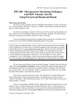
PIC16F876 Microcontroller
This powerful (200 nanosecond instruction execution) yet easy-to-
program (only 35 single-word instructions) CMOS flash-based 8-bit
microcontroller packs Microchip’s powerful programmable integrated
circuit (PIC) architecture into an 18-pin package, and is upwards com-
patible with the PIC16C7x, PIC16C62xA, PIC16C5X, and PIC12CXXX
devices. The PIC16F876 features 8 MHz internal oscillator, 256 bytes
of EEPROM data memory, a capture/compare/PWM, an addressable
USART, and two comparators that make it ideal for advantage ana-
log/integrated level applications in automotive, industrial, appliances,
and consumer applications (see Figure 2.5).
See Chapter 7: Programming the PIC16F876 Microcontroller for more
information.
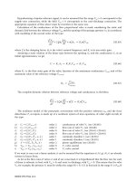
L7805ACV Voltage Regulator (5 Volts)
The L7800A series of three terminal positive regulators is available in
TO-220, TO-220FP, and D
2
PAK packages and several fixed output volt-
ages, making it useful in a wide range of applications. These regulators
PDA Robotics
18
Figure 2.5
The PIC16F876.
PDA 02 5/27/03 8:20 AM Page 18
can provide local on-card regulation, eliminating the distribution
problem associated with single point regulation. Each type employs
internal current limiting, thermal shutdown, and safe area protection,
making it essentially indestructible. If adequate heat sinking is pro-
vided, they can deliver over 1A output current. Although designed
primarily as fixed voltage regulators, these devices can be used with
external components to obtain adjustable voltage and currents. Note:
PDABot draws very little current, so heat sinking is not necessary.
Figure 2.6 shows the available packages.
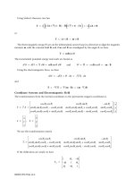
L298 Dual Full-Bridge Driver
The L298 is used in PDA Robot to drive the two DC motors. It is an
integrated monolithic circuit in 15-lead Multiwatt and Power SO20
packages. It is a high-voltage, high-current dual full-bridge driver
designed to accept standard TTL logic levels and drive inductive loads
such as relays, solenoids, DC, and stepping motors. Two enable inputs
are provided to enable or disable the device independently of the
input signals. The emitters of the lower transistors of each bridge are
connected together, and the corresponding external terminal can be
used for the connection of an external sensing resistor. Additional
supply input is provided so that the logic works at a lower voltage.
Figure 2.7 illustrates the physical layout of the L298.
Chapter 2 / Robotic System Overview
19
Figure 2.6
The L7800A
chipset.
PDA 02 5/27/03 8:20 AM Page 19
Sharp GP2D12 Infrared Range Finder
The GP2D12 is a compact, self-contained IR ranging system incorpo-
rating an IR transmitter, receiver, optics, filter, detection, and amplifi-
cation circuitry (see Figure 2.8). Along with the wireless video cam-
era, it gives PDA Robot a sense of sight, allowing it to navigate
autonomously around objects. The unit is highly resistant to ambient
light and nearly impervious to variations in the surface reflectivity of
the detected object. Unlike many IR systems, this has a fairly narrow
field of view, making it easier to get the range of a specific target. The
field of view changes with the distance to an object, but is no wider
than 5 cm (2.5 cm either side of center) when measuring at the maxi-
mum range.
PDA Robotics
20
Figure 2.7
The L298 h-bridge
chipset.
Figure 2.8
The GP2D12.
PDA 02 5/27/03 8:20 AM Page 20
DYN2009635 20 MH and RXDMP49 11.0952 MHz “AT”
Cut Quartz Crystal Oscillator
The PIC16F876 RISC microcontroller uses a 20 MHz crystal, and the
MCP2150 uses an 11 MHz crystal. While the PIC16F876 has an 8 MHz
internal oscillator, a higher clock rate is desired for the communica-
tion link, analog input turnaround, and motor control reaction time
via the digital outputs. Figure 2.9 shows the physical dimensions of
the crystals.
Chapter 2 / Robotic System Overview
21
Figure 2.9
Physical dimensions
of the RXDMP49
and DYN2009635
crystal oscillators.
Side and bottom
views.
PDA 02 5/27/03 8:20 AM Page 21
This page intentionally left blank.
23
To complete the PDA Robot project, some tools like the soldering iron
are essential; some simply make the job easier. The following lists the
essentials and then the “nice to have equipment” you can buy when
your skill in electronics and software earns you a great living, with a
lot of excitement along the way!
Essential Tools and Equipment
Essentials, shown in Figure 3.1, include a screwdriver (A), a pair of
side cutting pliers (B), a utility knife (C), a simple multimeter (D), a
soldering iron (E), a ruler (F), a hack saw (G), a porcelain cooking tray,
and about 45 minutes time on a drill press (www.thinkbotics.com).
Buy a drill press if you plan on making a lot of circuits (see Figure 3.2).
Another very useful tool is a chip puller. Quite often they come with
low-cost computer tool kits. When you reprogram the microchip
(PIC16F876) in this project, it needs to be pulled from the board, pro-
grammed, and reinserted. You can use your hands to pull the chips,
but you risk bending or squashing the pins, as well as frying chips
with a jolt of static electricity. I almost put the chip puller in the essen-
tial list until the couch swallowed mine, and I was simply (carefully)
pulling the chips from the board with my hand. A pair of wire cutters
for clipping the leads off the electronics components is helpful, in
Tools and
Equipment
3
PDA 03 5/27/03 8:23 AM Page 23
Copyright 2003 by The McGraw-Hill Companies, Inc. Click Here for Terms of Use.
PDA Robotics
24
Figure 3.1
The essential tools.
Figure 3.2
Drill press.
PDA 03 5/27/03 8:23 AM Page 24
addition to a file to smooth any metal edges. Figure 3.3 shows a chip
puller (A), wire cutters (B), and a file (C).
To make the job of soldering safe, get the tools shown in Figure 3.4,
including a good soldering iron holder (A). When hot, it is a fire haz-
ard. The soldering iron tip cleaner (B) makes soldering a lot faster and
ensures a high-quality weld. The solder sucker (C) helps to easily
remove a component or fix a bad spot.
Chapter 3 / Tools and Equipment
25
Figure 3.3
Tools.
Figure 3.4
Soldering tools.
PDA 03 5/27/03 8:23 AM Page 25
You will need four drill bits, shown in Figure 3.5, to complete the cir-
cuit board and body of PDA Robot. Use the 7/64 (A) to drill the holes
in the aluminum plates to mount the circuits, supports, and motors.
Use the 1/16 (B), 1/32 (C), and the 3/64 (D) to drill holes in the circuit
for the various components.
Safety First
Please do yourself a favor and buy eye protection. You need safety
glasses when drilling and etching the circuit board. Always use com-
mon sense around any equipment. Remember to unplug your solder-
ing iron before going out, especially if you have pets or small children.
PDA Robotics
26
Figure 3.5
Drill bits.
PDA 03 5/27/03 8:23 AM Page 26
Where to Get Equipment
Go to garage sales and flea markets to find some very good deals. A lot
of equipment is in great shape even after collecting dust for years in
people’s basements. Asking for tools for birthdays and Christmas is a
great way to acquire them over time if you are on a limited budget.
Chapter 3 / Tools and Equipment
27
Figure 3.6
Drilling the holes on
the circuit board.
PDA 03 5/27/03 8:23 AM Page 27
This page intentionally left blank.
29
Infrared (IR) radiation lies between the visible and microwave por-
tions of the electromagnetic spectrum, and is the medium that the per-
sonal digital assistant (PDA) uses to talk to the robot control circuitry
(see Figure 4.1).
IR light is broken into the following three categories.
• Near-infrared (near-IR)—Closest to visible light, near-IR has
wavelengths that range from 0.7 to 1.3 microns, or 700 billionths
to 1300 billionths of a meter.
• Mid-infrared (mid-IR)—Mid-IR has wavelengths ranging from 1.3
to 3 microns. Both near-IR and mid-IR are used by a variety of
electronic devices, including remote controls. It is in this mid
range that the PDA will communicate with the robotic body using
the Infrared Data Association (IrDA) communication protocol.
• Thermal-infrared (thermal-IR)—Occupying the largest part of the
IR spectrum, thermal-IR has wavelengths ranging from 3 microns
to over 30 microns.
The infrared emitters (IREDs) used for PDA devices fall into the near-
IR category.
PDABot will use an IrDA protocol called IrCOMM (9-wire “cooked”
service class) and the IrLMP. To simplify the task of using the IrDA
Infrared
Communications
Overview
4
PDA 04 5/27/03 8:27 AM Page 29
Copyright 2003 by The McGraw-Hill Companies, Inc. Click Here for Terms of Use.
protocol, PDABot uses a Microchip MCP2150, (see Figure 4.2) an IrDA
standard protocol stack controller, and a Vishay Telefunken TFDS4500
serial infrared transceiver (SIR 115.2 kb/s).
A widely used protocol that most devices using IR adhere to is IrDA.
Both Palm OS and Windows have incarnations of IrDA, which will be
explained in detail in Chapter 8: PDA Robot PalmOS Software Using
Code Warrior 8 and Chapter 9: PDA Robot Software for Pocket PC 2002
(Windows CE).
IrDA is an international organization that creates and promotes inter-
operable, low-cost IR data interconnection standards that support a
walk-up, point-to-point user model. The Infrared Data Association
PDA Robotics
30
Figure 4.1
PDA Robot’s IR
transceiver next to
an iPAQ 3850.
Figure 4.2
MCP2150 block
diagram.
PDA 04 5/27/03 8:27 AM Page 30
standards support a broad range of appliances, computing, and com-
munications devices. Figure 4.3 illustrates Windows IrDA architec-
ture, as defined today.
Technical Summary of IrDA Data
and IrDA Control
IrDA’s New Full Range of Digital Information
Exchange via Cordless IR Connections
Regarding present publications on IrDA features for PC99, IrDA Data
is recommended for high-speed, short-range, line-of-sight, point-to-
point cordless data transfer—suitable for handheld personal comput-
ers (HPCs), PDAs, digital cameras, handheld data collection devices,
etc. If IrDA is supported, it must be targeted at the 4 Mb/s components.
IrDA Control is recommended for in-room cordless peripherals to
hostPC. PC99 is for lower speed, full cross range, point-to-point or
point-to-multipoint cordless controller—suitable for keyboards (one-
way), joysticks (two-way and low latency), etc. IrDA Data and IrDA
Control require designer attention to ensure spatial or time-sharing
techniques, so as to avoid interference.
Since 1994, IrDA Data has defined a standard for an interoperable,
universal, two-way, cordless IR light transmission data port. IrDA
technology is already in over 300 million electronic devices including
desktops, notebooks, palm PCs, printers, digital cameras, public
phones/kiosks, cellular phones, pagers, PDAs, electronic books, elec-
tronic wallets, toys, watches, and other mobile devices.
Chapter 4 / Infrared Communications Overview
31
Figure 4.3
IrDA architecture.
PDA 04 5/27/03 8:27 AM Page 31
IrDA Data protocols consist of a mandatory set of protocols and a set
of optional protocols. The mandatory protocols include the following:
• Physical Signaling Layer (PHY)
• Link Access Protocol (IrLAP)
• Link Management Protocol/Information Access Service (IrLMP/
IAS)
Characteristics of Physical IrDA Data Signaling:
• Range: Continuous operation from contact to at least one (typical-
ly two can be reached). A low-power version relaxes the range
objective for operation from contact through at least 20 cm
between low-power devices, and 30 cm between low-power and
standard-power devices. This implementation affords 10 times
less power consumption. These parameters are termed the
required maximum ranges by certain classes of IrDA featured
devices, and set the end-user expectation for discovery, recogni-
tion, and performance.
• Bidirectional communication is the basis of all specifications.
• Data transmission from 9600 b/s with primary speed/cost steps
of 115 kb/s and maximum speed up to 4 Mb/s.
• Data packets are protected using a cyclic redundancy check (CRC)
(CRC-16 for speeds up to 1.152 Mb/s and CRC-32 at 4 Mb/s).
Characteristics of IrDA Link Access Protocol (IrLAP):
• Provides a device-to-device connection for the reliable, ordered
transfer of data.
• Device discovery procedures.
• Handles hidden nodes.
Characteristics of IrDA Link Management Protocol (IrLMP):
• Provides multiplexing of the IrLAP layer.
• Provides multiple channels above an IrLAP connection.
• Provides protocol and service discovery via the Information
Access Service (IAS).
PDA Robotics
32
PDA 04 5/27/03 8:27 AM Page 32
Optional IrDA Data Protocols
The optional IrDA data protocols include the following:
• Tiny TP provides flow control on IrLMP connections with an
optional segmentation and reassembly service.
• IrCOMM provides COM (serial and parallel) port emulation for
legacy COM applications, printing, and modem devices.
• OBEX™ provides object exchange services similar to hypertext
transfer protocol (HTTP).
• IrDA Lite provides methods of reducing the size of IrDA code,
while maintaining compatibility with full implementations.
• IrTran-P provides image exchange protocol used in digital image
capture devices/cameras.
• IrMC provides specifications on how mobile telephony and com-
munication devices can exchange information. This includes
phone book, calendar, and message data, as well as how call con-
trol and real-time voice are handled (RTCON) via calendar.
• IrLAN describes a protocol used to support IR wireless access to
local area networks.
IrDA Control
IrDA Control is an IR communication standard that allows cordless
peripherals such as keyboards, mice, game pads, joysticks, and point-
ing devices to interact with many types of intelligent host devices.
Host devices include PCs, home appliances, game machines, and tel-
evision/Web set-top boxes. IrDA Control is well suited to deal with
devices that leverage the USB HID class of device controls and home
appliances.
IrDA Control protocols consist of a mandatory set of protocols, including:
• PHY (Physical Layer)
• MAC (Media Access Control)
• LLC (Logical Link Control)
Chapter 4 / Infrared Communications Overview
33
PDA 04 5/27/03 8:27 AM Page 33
Characteristics of IrDA Control Physical Signaling:
• Distance and range equivalent current unidirectional IR remote
control units (minimum 5 m range).
• Bidirectional communication is the basis of all specs.
• Data transmission at 75 kb/s at the top end.
• The data are coded using a 16-pulse sequence multiplied by a
1.5-MHz subcarrier, which is allocated for high-speed remote
control in IEC 1603-1, although this base band scheme has har-
monics that can intrude upon other IEC bands.
• Data packets are protected with a CRC (CRC-8 for short packets
and CRC-16 for long packets). The physical layer is optimized
for low-power usage and can be implemented with low-cost
hardware.
Characteristics of IrDA Control MAC:
• Enables a host device to communicate with multiple peripheral
devices (1:n) and up to eight peripherals simultaneously.
• Ensures fast response time (13.8 ms basic polling rate) and low
latency.
Asymmetric MAC provides for dynamic assignment and reuse of
peripheral addresses. Scheduling of media access is actually buried in
the HID LLC.
Characteristics of the IrDA Control LLC:
• Provides reliability features that provide data sequencing and
retransmission when errors are detected.
• Works with an HID-IrDA control bridge to enable the link control
functions of USB-HID.
• All required and optional layers of the IrDA Data and IrDA
Control specifications are described in specifications that can be
downloaded at no charge from the IrDA Web site: www.irda.org.
Interop product registration is strongly advised on this site.
PDA Robotics
34
PDA 04 5/27/03 8:27 AM Page 34
IrDA specifications are now supported by all divisions of Microsoft
(IDG, WinCE, Win98, Win2000, and Windows XP), and this universal
data port is recommended on PC99 products (mandated on certain
WinCE products—PalmPC, etc.)
PDA Robot will use the IrDA Data protocol, not the IrDA Control pro-
tocol, to ensure a reliable high-speed bidirectional flow of data
between the body and the brain (PDA). All decisions will be made on-
board the PDA, using the software outlined in this book.
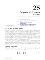
Windows CE (Pocket PC) and IrDA
One of the key features of Windows CE-based devices is the ability to
communicate with other devices. Windows CE supports two basic
types of communication: serial communication and communication
over a network. Most devices feature built-in communications hard-
ware, such as a serial port or an IR transceiver. The network driver
interface specification (NDIS) implementation on Windows CE sup-
ports the following communications media: Ethernet (802.3), Token
Ring (802.5), IrDA, and wide area network (WAN). The diagram shown
in Figure 4.4 outlines the communications architecture of the
Windows CE operating system, specifically the components of the
IrDA protocol layer and how IrDA miniport drivers communicate
through the NDIS library, with their network interface cards (NICs)
and applications.
In the Windows CE communications architecture, the NDIS interface
is located below the IrDA, transmission control protocol/Internet pro-
tocol (TCP/IP), and point-to-point protocol (PPP) drivers. The NDIS
wrapper presents an interface to the upper and lower edges of a mini-
port driver. To an upper-level driver, such as the TCP/IP protocol driv-
er, the NDIS interface looks like a miniport driver. To the miniport, the
NDIS interface looks like an upper-level protocol driver. On the bot-
tom of the communications architecture, the NDIS interface functions
as a network adapter driver that interfaces directly with the network
adapter at the lower edge. At the upper edge, the network adapter
driver presents an interface to allow upper layers to send packets on
the network, handle interrupts, reset or halt the network adapter, and
query or set the operational characteristics of the driver.
Chapter 4 / Infrared Communications Overview
35
PDA 04 5/27/03 8:27 AM Page 35
Communication Link Speeds
Unlike typical NDIS media, the IR medium supports a large number of
different speeds for transmitting and receiving bits. Current defini-
tions for operating speed vary from 2400 bits per second (b/s) to 16
megabits per second (Mb/s). In the future, more speeds may be defined
by IrDA. Varying design goals at different speeds have led to different
coding methods for frames: SIR, MIR, FIR, and VFIR. The differences
in frame coding methods must be handled by the IrDA miniport driv-
er and be transparent to the protocol.
The currently defined IrDA speeds and their corresponding frame cod-
ing methods (Serial IrDA [SIR] link speeds, Medium IrDA [MIR] link
speeds, Fast IrDA [FIR] link speeds, and Very Fast IrDA [VFIR] link
speeds) are listed in Table 4.1.
PDA Robotics
36
Figure 4.4
Windows
communication
architecture.
PDA 04 5/27/03 8:27 AM Page 36
Speed (in bps) Frame Coding Method
2400 SIR
9600 SIR
19,200 SIR
38,400 SIR
57,600 SIR
115,200 SIR
576,000 MIR
1.152 Mb/s MIR
4 Mb/s FIR
16 Mb/s VFIR
Communication Link Turnaround Times
An IR adapter consists of an IR transceiver, along with supporting
hardware for encoding and decoding frames. This IR transceiver con-
tains a transmitter light-emitting diode (LED) and a receiver diode that
are typically located quite close together. The receiver diode is sensi-
tive to IR light because it must receive transmissions from a remote IR
LED over distances up to at least 1 m. The transmitter LED is quite
powerful because it must transmit to a remote receiver diode over the
same distances.
During transmission, a local LED typically emits enough light to satu-
rate the local receiver diode. In much the same way that it is difficult
for people to see well after staring at the sun, it is difficult for the local
receiver diode to correctly receive incoming frames immediately after
the local LED transmits outgoing frames.
To allow time for the local receiver diode to recover from the satura-
tion state and become capable of again receiving incoming frames, the
IrDA protocol defines a parameter known as turnaround time.
Turnaround time specifies the amount of time, in milliseconds, that it
takes the receiver diode to recover from saturation. In some IrDA
devices, the turnaround time may be negligible; in other IrDA devices,
it can be a relatively long period of time.
The turnaround time of the local receiver diode does not affect the
behavior of the local transceiver. However, the turnaround time of the
local receiver diode affects the anticipated behavior of the remote
transceiver. For example, if a local transceiver requires a 1-ms delay
Chapter 4 / Infrared Communications Overview
37
Table 4.1
IrDA Speeds and
Corresponding
Frame Coding
Methods
PDA 04 5/27/03 8:27 AM Page 37