McGraw-Hill PDA Robotics 2003 (By.Laxxuss) Part 5 ppt
Bạn đang xem bản rút gọn của tài liệu. Xem và tải ngay bản đầy đủ của tài liệu tại đây (263.11 KB, 20 trang )
the microcontroller or the microprocessor is unable to drive the sup-
ply current required by the transceiver, a low-cost SOT23 pnp transis-
tor can be used to switch voltage on and off from the regulated power
supply. The additional component cost is minimal, and saves the sys-
tem designer additional power supply costs.
The 5-V regulator on the main board powers the transceiver in PDA
Robot.
The Microchip MCP2150 Plug and Play IrDA
The MCP2150 is a cost-effective, low pin-count (18-pin), easy to use
device for implementing IrDA standard wireless connectivity. The
MCP2150 provides support for the IrDA standard protocol “stack,”
plus bit encoding/decoding.
The serial interface baud rates are user selectable to one of four IrDA
standard baud rates between 9600 baud and 115.2 kbaud (9600, 19200,
57600, 115200). The IR baud rates are user selectable to one of five
IrDA standard baud rates between 9600 baud and 115.2 kbaud (9600,
19200, 37400, 57600, 115200). The serial interface baud rate will be
specified by the BAUD1:BAUD0 pins, while the IR baud rate is speci-
fied by the primary device (during Discover phase). This means that
the baud rates do not need to be the same.
The MCP2150 operates in data terminal equipment (DTE) applications
and sits between a UART and an IR optical transceiver. The MCP2150
encodes an asynchronous serial data stream, converting each data bit
to the corresponding IR formatted pulse. IR pulses received are decod-
ed and then handled by the protocol handler state machine. The pro-
tocol handler sends the appropriate data bytes to the host controller in
UART formatted serial data.
The MCP2150 supports point-to-point applications, that is, one pri-
mary device and one secondary device. The MCP2150 operates as a
secondary device. It does not support multipoint applications. Sending
data using IR light requires some hardware and the use of specialized
communication protocols. These protocol and hardware requirements
are described, in detail, by the IrDA standard specifications.
The chapters dealing with the software for the PDAs explain, in detail,
how to implement the specialized communication protocols.
PDA Robotics
58
PDA 05 5/30/03 11:35 AM Page 58
The encoding/decoding functionality of the MCP2150 is designed to
be compatible with the physical layer component of the IrDA stan-
dard. This part of the standard is often referred to as “IrPHY.” The
complete IrDA standard specifications are available for download
from the IrDA Web site (www.IrDA.org).
MCP2150 Applications: PDA Robot
The MCP2150 infrared communications controller supporting the
IrDA standard provides embedded system designers the easiest way to
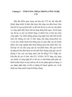
implement IrDA standard wireless connectivity. Figure 5.20a shows a
typical application block diagram. IR communication is a wireless
two-way data connection, using IR light generated by low-cost trans-
ceiver signaling technology. This provides reliable communication
between two devices. Reliability is the main reason I chose this proto-
col and this chip. It certainly simplifies the task of creating the PDA-
to-Robot data link. You can port the PDA code to the PIC microcon-
troller if you have the time.
IR technology has the following advantages:
• Universal standard for connecting portable computing devices.
• Easy, effortless implementation.
• Economical alternative to other connectivity solutions.
• Reliable, high-speed connection.
• Safe to use in any environment (can even be used during air
travel).
• Eliminates the hassle of cables and the possibility of damage to
your PDA.
• Allows PCs and other electronic devices (such as PDAs, cell
phones, etc.) to communicate with each other. In this case it
allows the PDA to communicate with PDA Robot.
• Enhances mobility by allowing users to easily connect.
The MCP2150 allows the easy addition of IrDA standard wireless con-
nectivity to any embedded application that uses serial data. Figure
5.20a shows typical implementation of the MCP2150 in an embedded
system.
Chapter 5 / The Electronics
59
PDA 05 5/30/03 11:35 AM Page 59
Table 5.2 describes the MCP2150 pins for the 18-pin dual in-line pack-
age used in PDA Robot’s circuit.
Table 5.2
MCP2150 DIP Pin Descriptions
Pin Pin Buffer
Name Pin # Type Type Description
BAUD0 1 I ST BAUD1:BAUD0 specify the baud rate of the device.
TXIR 2 O _ Asynchronous transmit to IR transceiver.
RXIR
3 I ST Asynchronous receive from IR transceiver.
RESET 4 I ST Resets the device.
VSS
5 _ P Ground reference for logic and I/O pins.
EN
6 I TTL Device enable.
1 = Device is enabled.
0 = Device is disabled (low power). MCP2150 only
monitors this pin when in the NDM state.
TX 7 I TTL Asynchronous receive; from host controller UART.
RX 8 O _ Asynchronous transmit; to host controller UART.
RI 9 _ _ Ring indicator. The value on this pin is driven high.
DSR 10 O _ Data Set Ready. Indicates that the MCP2150 has
completed reset.
1 = MCP2150 is initialized.
0 = MCP2150 is not initialized.
(continued on next page)
PDA Robotics
60
Figure 5.20a
A typical application
block diagram.
PDA 05 5/30/03 11:35 AM Page 60
Table 5.2
MCP2150 DIP Pin Descriptions (continued)
Pin Pin Buffer
Name Pin # Type Type Description
DTR 11 I TTL Data Terminal Ready. The value of this pin is ignored
once the MCP2150 is initialized. It is recommended that
this pin be connected so that the voltage level is either
VSS or VCC. At device power up, this signal is used with
the RTS signal to enter device ID programming.
1 = Enter Device ID programming mode (if RTS is
cleared).
0 = Do not enter Device ID programming mode.
CTS 12 O _ Clear to Send. Indicates that the MCP2150 is ready to
receive data from the host controller.
1 = Host controller should not send data.
0 = Host controller may send data.
RTS 13 I TTL Request to Send. Indicates that a host controller is
ready to receive data from the MCP2150. The MCP2150
prepares to send data, if available.
1 = Host controller not ready to receive data.
0 = Host controller ready to receive data.
At device power up, this signal is used with the DTR
signal to enter device ID programming.
1 = Do not enter device ID programming mode.
0 = Enter device ID programming mode (if DTR is set).
VDD 14 _ P Positive supply for logic and I/O pins.
OSC2 15 O _ Oscillator crystal output.
OSC1/CLKIN 16 I CMOS Oscillator crystal input/external clock source
input.
CD 17 O _ Carrier Detect. Indicates that the MCP2150 has
established a valid link with a primary device.
1 = An IR link has not been established (No IR Link).
0 = An IR link has been established (IR Link).
BAUD1 18 I ST BAUD1:BAUD0 specify the baud rate of the device.
Legend: TTL = TTL compatible input; I = Input; P = Power; ST = Schmitt Trigger input with
CMOS levels; O = Output; CMOS = CMOS compatible input
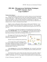
Power Up. Figure 5.20b shows the pin’s physical layout conforming
to the numbering convention of first pin to the top left and the num-
bers wrapping around the bottom of the chip so that pin 1 is opposite
pin 18.
Any time the device is powered up (parameter D003), the Power Up
Timer delay (parameter 33) occurs, followed by an Oscillator Start-up
Chapter 5 / The Electronics
61
PDA 05 5/30/03 11:35 AM Page 61
Timer (OST) delay (parameter 32). Once these delays complete, com-
munication with the device may be initiated. This communication is
from both the IR transceiver’s side, as well as the controller’s UART
interface.
Device Reset. The MCP2150 is forced into the reset state when the
RESET pin is in the low state. Once the RESET pin is brought to a high
state, the Device Reset sequence occurs. Once the sequence completes,
functional operation begins.
Clock Source. The MCP2150 requires a clock source to operate. The
frequency of this clock is 11.0592 MHz (electrical specification param-
eter 1A). This clock can be supplied by either a crystal/resonator or as
an external clock input.
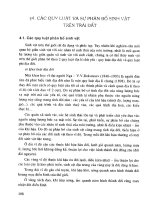
Crystal Oscillator/Ceramic Resonators
A crystal or ceramic resonator can be connected to the OSC1 and
OSC2 pins to establish oscillation (Figure 5.21). The MCP2150 oscil-
lator design requires the use of a parallel cut crystal. Use of a series cut
crystal may give a frequency outside of the crystal manufacturer’s
specifications.
PDA Robot uses 22 pf capacitors for both the MCP2150 and
PIC16F876. The values can range from 10 to 22 pf for a ceramic res-
onator and 15 to 30 pf for a crystal oscillator. Because PDA Robot uses
PDA Robotics
62
Figure 5.20b
MCP2150 pin’s
pyhsical layout.
PDA 05 5/30/03 11:35 AM Page 62
crystal oscillators, the 22 pf value provides good stability and an aver-
age start-up time. It also allows us to simply swap in a ceramic res-
onator if desired.
Higher capacitance increases the stability of the oscillator, but also
increases the start-up time. The resistor (RS) may be required to avoid
overdriving crystals with low drive level specification. Since each
crystal has its own characteristics, the user should consult the crystal
manufacturer for appropriate values of external components.
Bit Clock
The device crystal is used to derive the communication bit clock (BIT-
CLK). There are 16 BITCLKs for each bit time. The BITCLKs are used
for the generation of the start bit and the eight data bits. The stop bit
uses the BITCLK when the data are transmitted (not for reception).
This clock is a fixed frequency and has minimal variation in frequen-
cy (specified by crystal manufacturer).
UART Interface
The UART interface communicates with the controller. This interface
is a half-duplex interface, meaning that the system is either transmit-
ting or receiving, but not both simultaneously.
Baud Rate
The baud rate for the MCP2150 serial port (the TX and RX pins) is con-
figured by the state of the BAUD1 and BAUD0 pins. These two device
pins are used to select the baud rate at which the MCP2150 will trans-
mit and receive serial data (not IR data).
Chapter 5 / The Electronics
63
Figure 5.21
Crystal operation
(or ceramic
resonator). Note: A
series resistor may
be required for AT
strip cut crystals.
PDA 05 5/30/03 11:35 AM Page 63
Transmitting
When the controller sends serial data to the MCP2150, the controller’s
baud rate is required to match the baud rate of the MCP2150’s serial port.
Receiving
When the controller receives serial data from the MCP2150, the con-
troller’s baud rate is required to match the baud rate of the MCP2150’s
serial port. Matching up the baud rate of the microcontroller to that set
by the DIP switches is done in the software that is loaded into PDA
Robot’s microcontroller. Chapter 7: Programming the PIC16F876
Microcontroller explains this in detail.
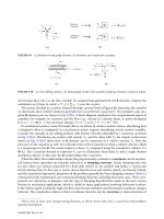
Modulation
The data that the MCP2150 UART received (on the TX pin) that needs
to be transmitted (on the TXIR pin) will need to be modulated. This
modulated signal drives the IR transceiver module. Figure 5.22 shows
the encoding of the modulated signal. Each bit time is comprised of 16-
bit clocks. If the value to be transmitted (as determined by the TX pin)
is a logic low, then the TXIR pin will output a low level for 7-bit clock
cycles, a logic high level for 3-bit clock cycles, or a minimum of 1.6 µs.
(see parameter IR121). The remaining 6-bit clock cycles will be low. If
the value to transmit is a logic high, then the TXIR pin will output a
low level for the entire 16-bit clock cycles. Note: The signal on the
TXIR pin does not actually line up in time with the bit value that was
transmitted on the TX pin, as shown in Figure 5.22. The TX bit value
is shown to represent the value to be transmitted on the TXIR pin.
PDA Robotics
64
Figure 5.22
MCP2150 data encoding (modulated).
PDA 05 5/30/03 11:35 AM Page 64
Demodulation
The modulated signal (data) from the IR transceiver module (on RXIR
pin) needs to be demodulated to form the received data (on RX pin).
Once demodulation of the data byte occurs, the received data are
transmitted by the MCP2150 UART (on the RX pin). Figure 5.23 illus-
trates the data decoding. Note: The signal on the RX pin does not actu-
ally line up in time with the bit value that was received on the RXIR
pin, as shown in Figure 5.23. The RXIR bit value is shown to represent
the value to be transmitted on the RX pin.
Minimizing Power
The device can be placed in a low-power mode by disabling the device
(holding the EN pin at the low state). The internal state machine is
monitoring this pin for a low level. Once this is detected, the device is
disabled and enters into a low-power state.
Returning to Device Operation
When disabled, the device is in a low-power state. When the EN pin
is brought to a high level, the device will return to the operating mode.
The device requires a delay of 1024 TOSC before data may be trans-
mitted or received.
Network Layering Reference Model
Figure 5.24 shows the Open Systems Interconnect (OSI) Network
Layering Reference Model. The shaded areas are implemented by the
Chapter 5 / The Electronics
65
Figure 5.23
MCP2150 data encoding (demodulated).
PDA 05 5/30/03 11:35 AM Page 65
MCP2150; the cross-hatched area is implemented by an IR transceiv-
er. The unshaded areas should be implemented by the host controller.
IrDA Data Protocols Supported by MCP2150
The MCP2150 supports the following required IrDA standard protocols:
• Physical Signaling Layer (PHY)
• Link Access Protocol (IrLAP)
• Link Management Protocol/Information Access Service (IrLMP/
IAS)
The MCP2150 also supports some of the optional protocols for IrDA
data. The optional protocols that the MCP2150 implements are:
• Tiny TP
• IrCOMM
PDA Robotics
66
Figure 5.24
OSI layers.
PDA 05 5/30/03 11:35 AM Page 66
The software running on the PDA utilizes all the optional and required
protocols supported by the MCP2150 (see Chapters 8 and 9).
Figure 5.25 shows the IrDA data protocol stack and which components
are implemented by the MCP2150. The optional IR transceiver for the
asynchronous serial IR is the Vishay transceiver described earlier.
Physical Signal Layer (PHY). The MCP2150 provides the following
Physical Signal Layer specification support:
• Bidirectional communication.
• Data Packets are protected by a CRC—16-bit CRC for speeds up
to 115.2 kbaud.
• Data Communication Rate—9600 baud minimum data rate.
Chapter 5 / The Electronics
67
Figure 5.25
MCP2150 IrDA
protocol stack.
PDA 05 5/30/03 11:35 AM Page 67
The following Physical Layer Specification is dependent on the opti-
cal transceiver logic used in the application. The specification states:
• Communication range, which sets the end user expectation for
discovery, recognition, and performance.
• Continuous operation from contact to at least 1 m (typically 2 m
can be reached).
• A low power specification reduces the objective for operation
from contact to at least 20 cm (low power and low power) or 30
cm (low power and standard power).
IrLAP. The MCP2150 supports the IrLAP. The IrLAP provides:
• Management of communication processes on the link between
devices.
• A device-to-device connection for the reliable, ordered transfer
of data.
• Device discover procedures.
• Hidden node handling.
Figure 5.26 identifies the key parts and hierarchy of the IrDA proto-
cols. The bottom layer is the Physical layer, IrPHY. This is the part that
converts the serial data to and from pulses of IR light. IR transceivers
can’t transmit and receive at the same time. The receiver has to wait
for the transmitter to finish sending. This is sometimes referred to as
a “half-duplex” connection. The IR IrLAP provides the structure for
PDA Robotics
68
Figure 5.26
Key IrDA protocols.
PDA 05 5/30/03 11:35 AM Page 68
packets (or “frames”) of data to emulate data that would normally be
free to stream back and forth.
IRDA Standard Protocol Layers
The IrLAP frame is proceeded by some number of Beginning of Frame
characters (BOFs). The value of the BOF is generally 0xC0, but 0xFF
may be used if the last BOF character is a 0xC0. The purpose of mul-
tiple BOFs is to give the other station some warning that a frame is
coming. The IrLAP frame begins with an address byte (“A” field), then
a control byte (“C” field). The control byte is used to differentiate
between different types of frames and is also used to count frames.
Frames can carry status, data, or commands. The IrLAP has a com-
mand syntax of its own. These commands are part of the control byte.
Last, IrLAP frames carry data. These data are the information (or “I”)
field. The integrity of the frame is ensured with a 16-bit CRC, referred
to as the frame check sequence (FCS). The 16-bit CRC value is trans-
mitted least signification bit (LSB) first. The end of the frame is
marked with an end of frame (EOF) character, which is always a 0xC1.
The frame structure described here is used for all versions of IrDA pro-
tocols used for serial wire replacement for speeds up to 115.2 kbaud.
In addition to defining the frame structure, IrLAP provides the “house-
keeping” functions of opening, closing, and maintaining connections.
The critical parameters that determine the performance of the link are
part of this function. These parameters control how many BOFs are
used, identify the speed of the link, how fast either party may change
from receiving to transmitting, etc. IrLAP has the responsibility of
negotiating these parameters to the highest common set so that both
sides can communicate as quickly, and as reliably, as possible. This is
done during the handshaking phase when the PDA is connecting to
PDA Robot.
IrLMP. The MCP2150 implements the IrLMP. The IrLMP provides:
• Multiplexing of the IrLAP layer. This allows multiple channels
above an IrLAP connection.
• Protocol and service discovery via the IAS.
When two devices that contain the IrDA standard feature are connected,
generally one device has something to do and the other device has the
Chapter 5 / The Electronics
69
PDA 05 5/30/03 11:35 AM Page 69
resource to do it. For example, a laptop may have a job to print and an
IrDA standard compatible printer has the resources to print it. In IrDA
standard terminology, the laptop is a primary device and the printer is
the secondary device. When these two devices connect, the primary
device must determine the capabilities of the secondary device to deter-
mine if the secondary device is capable of doing the job. This determi-
nation is made by the primary device asking the secondary device a
series of questions. Depending on the answers to these questions, the pri-
mary device may or may not elect to connect to the secondary device.
The queries from the primary device are carried to the secondary
device using IrLMP. The responses to these queries can be found in the
IAS of the secondary device. The IAS is a list of the resources of the
secondary device. The primary device compares the IAS responses
with its requirements, and then makes the decision if a connection
should be made. For instance, the software running on the PDA
queries PDA Robot to see what it identifies itself as, and to see if it will
accept the “cooked-wire” service. If it identifies itself as what we are
looking for and supports the service, then a connection is made.
The MCP2150 identifies itself to the primary device as a modem. The
MCP2150 is not a modem, and the nondata circuits are not handled in
a modem fashion.
Link Management-Information Access Service (LM-IAS). The
MCP2150 implements the LM-IAS. Each LM-IAS entity maintains an
information database to provide:
• Information on services for other devices that contain the IrDA
standard feature (Discovery).
• Information on services for the device itself.
• Remote accessing of another device’s information base.
This is required so clients on a remote device can find configuration
information needed to access a service.
Tiny TP. Tiny TP provides the flow control on IrLMP connections.
An optional service of Segmentation and Reassembly can be handled.
IrCOMM. IrCOMM provides the method to support serial and paral-
lel port emulation. This is useful for legacy COM applications, such as
PDA Robotics
70
PDA 05 5/30/03 11:35 AM Page 70
printers and modem devices. The IrCOMM standard is just a syntax
that allows the primary device to consider the secondary device as a
serial device. IrCOMM allows for emulation of serial or parallel (print-
er) connections of various capabilities.
The MCP2150 (PDA Robot) supports the 9-wire “cooked” service class
of IrCOMM. Other service classes supported by IrCOMM are shown in
Figure 5.27. Note: The MCP2150 identifies itself as a modem to ensure
that it is identified as a serial device with a limited amount of memory.
PDA and PDA Robot Handshake:
How Devices Connect
When two devices implementing the IrDA standard feature (PDA and
PDA Robot) establish a connection using the IrCOMM protocol, the
process is analogous to connecting two devices with serial ports using
a cable. This is referred to as a point-to-point connection. This con-
nection is limited to half-duplex operation because the IR transceiver
cannot transmit and receive at the same time. The purpose of the IrDA
protocol is to allow this half-duplex link to emulate, as much as pos-
sible, a full-duplex connection. In general, this is done by dividing the
data into “packets,” or groups of data. These packets can then be sent
back and forth, when needed, without risk of collision. The rules of
how and when these packets are sent constitute the IrDA protocols.
The MCP2150 supports elements of this IrDA protocol to communi-
cate with other IrDA standard compatible devices. When a wired con-
Chapter 5 / The Electronics
71
Figure 5.27
Services supported by IrCOMM.
PDA 05 5/30/03 11:35 AM Page 71
nection is used, the assumption is made that both sides have the same
communications parameters and features. A wired connection has no
need to identify the other connector because it is assumed that the
connectors are properly connected. In the IrDA standard, a connection
process has been defined to identify other IrDA compatible devices
and establish a communication link. These two devices (PDA and
PDA Robot) go through three steps to make this connection. They are:
• Normal disconnect mode (NDM)
• Discovery mode
• Normal connect mode (NCM)
Figure 5.28 shows the connection sequence.
Normal Disconnect Mode (NDM)
When two IrDA standard compatible devices come into range, they
must first recognize each other. The basis of this process is that one
device has some task to accomplish, and the other device has a
resource needed to accomplish this task. One device is referred to as a
primary device and the other is referred to as a secondary device. This
distinction between primary device and secondary device is impor-
tant. In our case, the PDA is the primary device and PDA Robot is the
secondary. It is the responsibility of the primary device to provide the
mechanism to recognize other devices.
So the primary device must first poll for nearby IrDA standard com-
patible devices. During this polling, the default baud rate of 9600 baud
is used by both devices. For example, to print from an IrDA-equipped
laptop to an IrDA printer, utilizing the IrDA standard feature, first
bring your laptop in range of the printer. In this case, the laptop has
something to do and the printer has the resource to do it. The laptop
is called the primary device and the printer is the secondary device.
Some data-capable cell phones have IrDA standard IR ports. If you
used such a cell phone with a PDA, the PDA that supports the IrDA
standard feature would be the primary device, and the cell phone
would be the secondary device.
When a primary device polls for another device, a nearby secondary
device may respond. When a secondary device responds, the two
devices are defined to be in the NDM state. NDM is established by the
PDA Robotics
72
PDA 05 5/30/03 11:35 AM Page 72
primary device broadcasting a packet and waiting for a response.
These broadcast packets are numbered. Usually 6 or 8 packets are sent.
The first packet is number 0, and the last packet is usually number 5
or 7. Once all the packets are sent, the primary device sends an ID
packet, which is not numbered. The secondary device waits for these
Chapter 5 / The Electronics
73
Figure 5.28
Connection sequence.
PDA 05 5/30/03 11:35 AM Page 73
packets, and then responds to one of the packets. The packet it
responds to determines the “time slot” to be used by the secondary
device. For example, if the secondary device responds after packet
number 2, then the secondary device will use time slot 2. If the sec-
ondary device responds after packet number 0, then the secondary
device will use time slot 0. This mechanism allows the primary device
to recognize as many nearby devices as there are time slots. The pri-
mary device will continue to generate time slots, and the secondary
device should continue to respond, even if there is nothing to do.
During NDM, the MCP2150 handles all of the responses to the primary
device (Figure 5.28) without any communication with the host con-
troller. The host controller is inhibited by the clear to send (CTS) sig-
nal of the MCP2150 from sending data to the MCP2150. Note the fol-
lowing:
• The MCP2150 can only be used to implement a secondary
device.
• The MCP2150 supports a system with only one secondary device
having exclusive use of the IrDA standard IR link (known as
point-to-point communication).
• The MCP2150 always responds to packet number 2. This means
that the MCP2150 will always use time slot 2.
• If another secondary device is nearby, the primary device may
fail to recognize the MCP2150, or the primary device may not
recognize either of the devices. This is not the case with the soft-
ware developed for the PDAs. I get a list of all secondary devices
that respond to the discovery request and look for the identifier
for PDA Robot, which is “Generic IrDA” (the default setting of
the MCP2150). My printer and PDA Robot always respond, and
the software only connects to PDA Robot.
Discovery Mode
Discovery mode allows the primary device to determine the capabili-
ties of the MCP2150 (secondary device). Discovery mode is entered
once the MCP2150 (secondary device) has sent an XID response to the
primary device and the primary device has completed sending the
XIDs, and then sends a Broadcast ID. If this sequence is not complet-
ed, then a primary and secondary device can stay in NDM indefinite-
PDA Robotics
74
PDA 05 5/30/03 11:35 AM Page 74
ly. When the primary device has something to do, it initiates
Discovery. Discovery has two parts. They are:
• Link initialization
• Resource determination
The first step is for the primary and secondary devices to determine,
and then adjust to, each other’s hardware capabilities. These capabili-
ties are parameters like:
• Data rate
• Turnaround time
• Number of packets without a response
• How long to wait before disconnecting
Both the primary and secondary device begin communications at 9600
baud, which is the default baud rate. The primary device sends its
parameters, then the secondary device responds with its parameters.
For example, if the primary supports all data rates up to 115.2 kbaud
and the secondary device only supports 19.2 kbaud, the link will be
established at 19.2 kbaud.
Once the hardware parameters are established, the primary device
must determine if the secondary device has the resources it requires.
If the primary device has a job to print, then it must know if it is talk-
ing to a printer, not a modem or other device. This determination is
made using the IAS. The job of the secondary device is to respond to
IAS queries made by the primary device. The primary device must ask
a series of questions like:
• What is the name of your service?
• What is the address of this service?
• What are the capabilities of this device?
When all the primary device’s questions are answered, the primary
device can access the service provided by the secondary device.
During Discovery mode, the MCP2150 handles all responses to the pri-
mary device (see Figure 5.28) without any communication with the
host controller. The host controller is inhibited by the CTS signal of
the MCP2150 from sending data to the MCP2150.
Chapter 5 / The Electronics
75
PDA 05 5/30/03 11:35 AM Page 75
Normal Connect Mode (NCM)
Once discovery has been completed, the primary device and MCP2150
(secondary device) can freely exchange data. The MCP2150 can
receive IR data or serial data, but not both simultaneously. The
MCP2150 uses a hardware handshake to stop the local serial port from
sending data while the MCP2150 is receiving IR data. Both the pri-
mary device and the MCP2150 (secondary device) check to make sure
that data packets are received by the other without errors. Even when
data is required to be sent, the primary and secondary devices will still
exchange packets to ensure that the connection has not, unexpected-
ly, been dropped.
When the primary device has finished, it then transmits the close
link command to the MCP2150 (secondary device). The MCP2150
will confirm the close link command, and both the primary device
and the MCP2150 (secondary device) will revert to the NDM state. It
is the responsibility of the host controller program to understand the
meaning of the data received and how the program should respond
to it. It is just as if the data were being received by the host controller
from a UART. Note: The MCP2150 is limited to a data rate of 115.2
kbaud. Data loss will result if this hardware handshake is not
observed. If the NCM mode is unexpectedly terminated for any rea-
son (including the primary device not issuing a close link com-
mand), the MCP2150 will revert to the NDM state 10 seconds after
the last frame has been received. Figure 5.28 shows the connection
sequence.
MCP2150 Operation
The MCP2150 emulates a null modem connection. The application on
the DTE device sees a virtual serial port. This serial port emulation is
provided by the IrDA standard protocols. The link between the DTE
device and the embedded application is made using the MCP2150.
The connection between the MCP2150 and the embedded application
is wired as if there were a null modem connection.
The carrier detect (CD) signal of the MCP2150 is used to indicate that
a valid IrDA standard IR link has been established between the
MCP2150 and the primary device. The CD signal should be moni-
tored closely to make sure that any communication tasks can be com-
pleted. The MCP2150 data signaling rate (DSR) signal indicates that
PDA Robotics
76
PDA 05 5/30/03 11:35 AM Page 76
the device has powered up, is successfully initialized, and is ready
for service. This signal is intended to be connected to the DSR input
of the host controller. If the host controller was directly connected to
an IrDA standard primary device using a serial cable (the MCP2150 is
not present), the host controller would be connected to the primary
device’s data transfer rate (DTR) output signal. The MCP2150 gener-
ates the CTS signal locally because of buffer limitations. Only the
transceiver’s TXD and RXD signals are carried back and forth to the
primary device. The MCP2150 emulates a three-wire serial connec-
tion (TXD, RXD, and GND).
The code for the PIC16F876 used in PDA Robot creates a three-wire
serial connection with the MCP2150 using the following line of code.
See Chapter 7: Programming the PIC16F876 Microcontroller.
#use rs232(baud=115200, xmit=PIN_B1, rcv=PIN_B0, stream=PDA)
Optical Transceiver
The MCP2150 requires an IR transceiver. The transceiver that we are
using is the TFDS4500, as described earlier in this chapter. The trans-
ceiver can be an integrated solution. A typical optical transceiver cir-
cuit, using a Vishay TFDS4500, is shown in Figure 5.29.
Chapter 5 / The Electronics
77
Figure 5.29
Typical transceiver
interface to the
MCP2150.
PDA 05 5/30/03 11:35 AM Page 77