MEMS and Microstructures in Aerospace Applications - Robert Osiander et al (Eds) Part 8 doc
Bạn đang xem bản rút gọn của tài liệu. Xem và tải ngay bản đầy đủ của tài liệu tại đây (1.27 MB, 14 trang )
mirror-shape stability and fabrication tolerances are of key concern to a system
designer. To this end preliminary MEMX devices were evaluated in terms of
angular jitter, focal spot stability, and open and closed-loop response versus laser
transmitter power at both ambient air and lower partial pressures. The applicability
and scalability of this technology to multiaccess terminals was also considered and
appears to be readily transferable to a space-qualified design. For most spacecraft
platforms micromirrors should be compatible with direct body-mounting because of
their high intrinsic bandwidth and controllable damping. (Being able to body-mount
these devices is highly desirable to take advantage of their low mass, which implies
spacecraft attitude control would be used for overall coarse pointing.) Importantly,
these optical beamsteerers are highly miniaturized, very lightweight, require very
little prime electrical low power, and are scalable to 2-D multichannel (point-to-
multi-point) links.
Initially a key concern about the MEMS micromirror performance in a space
environment was the effect of partial vacuum on heat dissipation from the trans-
mitting laser beam and on the degree of mechanical damping of the mirror. It is
important that the beamsteering controller be critically damped under suitable
partial or full atmospheric vapor pressure. In addition, a trade-off between
the optical power required to support the link and the degree of thermal heat
loading experienced by the mirror elements under pulsed laser light must also be
determined. Furthermore, any micromirror curvature change induced by laser heat-
ing must be avoided. To this end preliminary optical, dynamic, and thermal
measurements of the MEMX micromirrors were made using the optical test bed
shown in Figure 8.13.
Using experimental measurements, physical optics modeling, and computer-
based ray tracing, the laser beam quality reflected off a micromirror was evaluated.
This included observing the beam waist, beam shape, and beam jitter. A quad cell
detector and CCD focal plane array were used as diagnostic sensors in conjunction
with the setup described in Figure 8.13, which included a vacuum chamber. The
laser spot (with a minor axis of approximately 300 mm) is shown on the micromirror
as well as at the CCD output focal plane in their respective insets. One concern was
how much would the radius of curvature of the micromirror vary under light flux,
but this was not initially evaluated because previous work had shown that a limit of
about 300 mW would be sufficient to support projected link margins (even from
GEO). The other concern, apart from beam jitter, is beam quality, which turned out
to be poor because of an artifact of mirror fabrication, that resulted in etch pits in the
mirror surface causing a diffraction pattern in the focal plane, rather than a nominal
Gaussian spot, as shown in Figure 8.13 inset. This can be readily corrected in flat,
smooth mirror designs specific to the application and through spatial filtering.
Significant degradation, however, of the far-field beam should not be a real concern
if the mirror is redesigned.
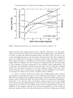
Micromirror frequency response measurements were made to establish basic
dynamic performance in ambient air, angle sensitivity to deflection voltage, and
dynamic response at lower pressures. The MEMX mirrors had very good frequency
response, out to almost 1 kHz (or more), as indicated in Figure 8.14(a), which is
Osiander / MEMS and microstructures in Aerospace applications DK3181_c008 Final Proof page 170 1.9.2005 12:05pm
170 MEMS and Microstructures in Aerospace Applications
© 2006 by Taylor & Francis Group, LLC
Mirror curvature variation from unit-to-unit was also assessed using a commer-
cial (Veeco) interferometer, and scans of two different mirrors are shown in
Figure 8.15(a) and (b). From these measurements the radii of curvature were
measured and found to vary by less than 10% (0.39 to 0.42 m), which is an
acceptable degree of diopter dispersion.
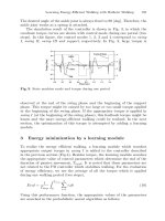
An initial demonstration of image tracking for beam steering was also con-
ducted using a commercial CMOS imager and one of the MEMS mirrors to direct a
transmitting (tracking) laser beam toward a moving target laser spot actuated by a
two-axis galvanometer. A simple centroiding algorithm was developed and tested
using a digital control system. The transmitting laser beam was observed to track
and follow a target spot as it moved across a white target plane. A block diagram of
the tracking system is shown in Figure 8.16 along with a photograph of the actual
tracking terminal.
A mapping between the FPA centroid position and a corresponding drive
command was also measured to determine the degree of nonlinearity in the device
derived from the lack of compliance of the mirror hinges at the extreme end of their
angular travel. Taking the polynomial fits in two orthogonal angles, which were
cross-coupled and varied with command voltages, attempts were made to linearize
these and modest improvements in performance were obtained. Thus, this nonli-
nearity can be potentially calibrated-out and compensated-for, or, better yet, re-
moved by redesign.
8.7.2 RECENT PROGRESS
Researchers at U.C., Berkeley, are also doing considerable work related to optical
communications using MEMS devices. They are investigating distributed networks
using millimeter-scale sensing elements implemented using MEMS, which are
called ‘‘Smart Dust,’’ which can be deployed either indoors or outdoors to sense
and record data of interest. Each ‘‘mote’’ contains a power source, sensors, data
FIGURE 8.15 (a) Overall MEMX micromirror structure as viewed by an optical interfer-
ometer before curvature measurement. The textured surface appearance is due to a release-
hole etch pattern; these will not be present on new mirror designs. (b) High-resolution scan by
the interferometer, showing curvature of another MEMX micromirror.
Osiander / MEMS and microstructures in Aerospace applications DK3181_c008 Final Proof page 173 1.9.2005 12:05pm
Microelectromechanical Systems for Spacecraft Communications 173
© 2006 by Taylor & Francis Group, LLC
single mirror to multiple mirrors (prior to a full 2-D design) is illustrated in
Figure 8.17 to delineate the essential elements required to implement MEMS
beam steering for optical satellite communications. A plan view of a possible 2-D
MEMX design is shown in Figure 8.18.
To/from
telephoto lens
MEMS
beamsteerer
array
Splitter
Splitter
CMOS
imager
Multi-channel
tracker
Collimator/laser diode array
Multi-channel
mod-demod
Receiver
detector array
FIGURE 8.17 Conceptual 1-D MEMS-based multichannel optical communications unit.
FIGURE 8.18 Plan-view of 2-D MEMS array using MEMX type micromirrors, suitable for
multichannel optical communications beam-steering.
Osiander / MEMS and microstructures in Aerospace applications DK3181_c008 Final Proof page 175 1.9.2005 12:05pm
Microelectromechanical Systems for Spacecraft Communications 175
© 2006 by Taylor & Francis Group, LLC
8.8 CONCLUSION
Space communications systems are ‘‘ripe’’ for the insertion of MEMS-based tech-
nologies, in part due to the growth in commercial communication developments.
One of the most exciting applications of MEMS for microwave communications in
spacecraft concerns the implementation of ‘‘active aperture phase array antennas.’’
These systems consist of groups of antennas phase-shifted from each other to
take advantage of constructive and destructive interference in order to achieve
high directionality. Such systems allow for electronically steered radiated and
received beams, which have greater agility and will not interfere with the satellite’s
position.
Optical communications could also play an important role in low-power, low-
mass, long-distance missions such as the Realistic InterStellar Explorer (RISE)
mission, which seeks to send an explorer beyond the solar system, which requires
traveling a distance of 200 to 1000 AU from the Sun within a timeframe of about 10
to 50 years. The primary downlink for such a satellite would need to be optical
because of the distances and weight limits involved. It has been proposed that a
MEMS implementation of the beam-steering mechanism may be necessary to
achieve the desired directional accuracy with a sufficiently low mass.
112
MEMS
in space communication may well fall under the trendy term ‘‘disruptive technol-
ogy’’ for their potential to redefine whole systems.
REFERENCES
1. Wertz, J.R. and Larson, W.J., Space Mission Analysis and Design. Microcosm Press, El
Segundo, California, 1999.
2. Morgan, W.L. and Gordon, G.D., Communications Satellite Handbook. John Wiley and
Sons, New York, 1989.
3. Wilson, K. and Enoch, M., Optical communications for deep space missions, IEEE
Communications, August 2000.
4. Begley, D.L., Laser cross-link systems and technology, IEEE Communications Maga-
zine, 38 (8), 126, 2000.
5. Scott, W.B., Micromachines hold promise for aerospace, Aviation Week and Space
Technology, March 1993.
6. Fiedziuszko, S.J., Applications of MEMS in communication satellites, Proceedings —
13th International Conference on Microwaves, Radar and Wireless Communications,
MIKON-2000, 3, 201, 2000.
7. Rebeiz, G.M., Tan, G L., and Hayden, J. S., IEEE Microwave Magazine, June 2002,
72.
8. Rebeiz, G.M., RF MEMS: Theory, Design, and Technology. Wiley-Interscience, Hobo-
ken, New Jersey, 2003.
9. Petersen, K.E., Micromechanical membrane switches on silicon, IBM Journal of Re-
search and Development, 23 (4), 376, 1979.
10. Goldsmith, C.L. et al., Performance of low-loss RF MEMS capacitive switches, IEEE
Microwave Guided Wave Letters, 8 (8), 269, 1998.
11. Yao, Z.J. et al., Micromachined low-loss microwave switches, Journal of Microelec-
tromechanical Systems, 8 (2), 129, 1999.
Osiander / MEMS and microstructures in Aerospace applications DK3181_c008 Final Proof page 176 1.9.2005 12:05pm
176 MEMS and Microstructures in Aerospace Applications
© 2006 by Taylor & Francis Group, LLC
12. Streeter, R.D. et al., VHF high-power tunable RF bandpass filter using microelectro-
mechanical (MEM) microrelays, International Journal of RF Microwave Compound
Aided Engineering, 11 (5), 261, 2001.
13. De Los Santos, H.J. et al., Microwave and mechanical considerations in the design of
MEM switches for aerospace applications, Proceedings — IEEE Aerospace Confer-
ence, 235, 1997.
14. Larson, L.E., Microactuators for GaAs-based microwave integrated circuits, Proceed-
ings — Transducers ’91, 743, 1991.
15. Hyman, D. et al., GaAs-compatible surface-micromachined RF MEMS switches, Elec-
tronic Letters, 35 (3), 224, 1999.
16. Hyman, D. and Mehregany, M., Contact physics of gold microcontacts for MEMS
switches, IEEE Transactions on Components and Packing Technologies, 22 (3), 357,
1999.
17. Muldavin, J.B. and Rebeiz, G.M., High-isolation CPW MEMS shunt switches — part 1:
modeling, IEEE Transactions on Microwave Theory and Techniques, 48 (6), 1045, 2000.
18. Muldavin, J.B. and Rebeiz, G.M., High-isolation CPW MEMS shunt switches — part 2:
design, IEEE Transactions on Microwave Theory and Techniques, 48 (6), 1053, 2000.
19. Barker, N.S. and Rebeiz, G.M., Distributed MEMS true-time delay phase shifters and
wide-band switches, IEEE Transactions on Microwave Theory and Techniques, 46
(11), 1881, 1998.
20. Wood, R. et al., MEMS microrelays, Mechatronics, 8, 535, 1998.
21. Seki, T. et al., Thermal buckling actuator for micro relays, Proceedings — Transducers
’97, 1153, 1997.
22. Brown, E.R., RF-MEMS switches for reconfigurable integrated circuits, IEEE Trans-
actions on Microwave Theory and Techniques, 46 (11), 1868, 1998.
23. Simon, J., Saffer, S., and Kim, C J., A liquid-filled microrelay with a moving mercury
microdrop, Journal of Microelectromechanical Systems, 6 (3), 208, 1997.
24. Yao, J.J. et al., Microelectromechanical system radio frequency switches in a picosa-
tellite mission, Smart Materials and Structures, 10, 1196, 2001.
25. Mihailovich, R.E. et al., MEM relay for reconfigurable RF circuits, IEEE Microwave
Guided Wave Letters, 11 (2), 53–55, 2001.
26. Yao, J.J., RF MEMS from a device perspective, Journal of Micromechanics and
Microengineering, 10, R9, 2000.
27. Yao, J.J. and Chang, M.F., A surface micromachined miniature switch for telecommu-
nications applications with signal frequencies from DC up to 4 GHz, Proceedings —
Transducers ’95, 1995.
28. Goldsmith, C. et al., Micromechanical membrane switches for microwave applications,
IEEE Microwave Theory Technical Symposium Digests, 91, 1995.
29. Goldsmith, C. et al., Characteristics of micromachined switches at microwave frequen-
cies, IEEE Microwave Theory Technical Symposium Digests, 1141, 1996.
30. Randall, J.N. et al., Fabrication of micromechanical switches for routing radio fre-
quency signals, Journal of Vacuum Science and Technology B
, 14 (6), 3692, 1996.
31. Jones, E.J., Micro and millimeter wave MEMS for phased arrays, Proceedings —
Gomac, 98, 1998.
32. Norvell, B.R. et al., Micro electro mechanical switch (MEMS) technology applied to
electronically scanned arrays for space based radar, Proceedings — Aerospace Confer-
ence, 3, 239, 1999.
33. Shen, S C. and Feng, M., Low actuation voltage RF MEMS switches with signal
frequencies from 0.25 GHz to 40 GHz, Proceedings — Transducers, 1999.
Osiander / MEMS and microstructures in Aerospace applications DK3181_c008 Final Proof page 177 1.9.2005 12:05pm
Microelectromechanical Systems for Spacecraft Communications 177
© 2006 by Taylor & Francis Group, LLC
34. Pacheco, S., Nguyen, C.T., and Katehi, L.P.B., Micromechanical electrostatic K-band
switches, Proceedings — IEEE MTT-S International Microwave Symposium, 1998.
35. Zhou, S., Sun, X Q., and Carr, W.S., A monolithic variable inductor network using
microrelays with combined thermal and electrostatic actuation, Journal of Microme-
chanics and Microenginnering, 9, 45, 1999.
36. Kruglick, E.J.J. and Pister, K.S.J., Lateral MEMS microcontact considerations, Journal
of Microelectromechanical Systems, 8 (3), 264, 1999.
37. Hosaka, H., Kuwano, H., and Yanagisawa, K., Electromagnetic microrelays: concepts
and fundamental characteristics, Sensors and Actuators A, 40, 41, 1994.
38. Kruglick, E.J.J. and Pister, K.S.J., Bistable MEMS relays and contact characterization,
Proceedings — Solid-State Sensor and Actuator Workshop, 333, 1998.
39. Chang, C. and Chang, P., Innovative micromachined microwave switch with very low
insertion loss, Sensors and Actuators A 79, 71, 2000.
40. Schiele, I. et al., Surface-micromachined electrostatic microrelay, Sensors and Actuators
A, 66, 345, 1998.
41. Hyman, D. et al., Surface-micromachined RF MEMs switches on GaAs substrates,
International Journal of RF Microwave Computer Aided Engineering, 9 (4), 348, 1999.
42. Schimkat, J., Contact materials for microrelays, Proceedings — 11th Annual Inter-
national Workshop on Micro Electro Mechanical Systems, 190, 1998.
43. Schimkat, J., Contact measurements providing basic design data for microrelay actu-
ators, Sensors and Actuators, 73, 138, 1999.
44. Pillans, B., RF power handling of capacitive RF MEMS devices, Proceedings — 2002
IEEE MTT-S International Microwave Symposium Digests, 329, 2002.
45. Wibbeler, J., Pfeifer, G., and Hietschold, M., Parasitic charging of dielectric surfaces in
capacitive microelectromechanical systems (MEMS), Sensors and Actuators A, 71, 74,
1998.
46. Ko, Y.J., Park, J.Y., and Bu, J.U., Integrated 3-bit RF MEMS phase shifter with
constant phase shift for active phased array antennas in satellite broadcasting systems,
Proceedings — Transducers ’03, 1788, 2003.
47. Kim, M. et al., A DC-to-40 GHz four-bit RF MEMS true-time delay network, IEEE
Microwave Wireless Component Letters, 11 (2), 56, 2001.
48. Tan, G L. et al., Low-loss 2- and 4-bit TTD MEMS phase shifters based on SP4T
switches, IEEE Transactions on Microwave Theory and Techniques, 51 (1), 297, 2003.
49. Hacker, J.B. et al., A Ka-Band 3-bit RF MEMS true-time-delay network, IEEE Trans-
actions on Microwave Theory and Techniques, 51 (1), 305, 2003.
50. Pillans, B. et al., Ka-band RF MEMS phase shifters, IEEE Microwave Guided Wave
Letters, 9 (12), 520, 1999.
51. Pozar, D.M., Microwave Engineering. John Wiley and Sons, New York, 1998.
52. Hayden, J.S. and Rebeiz, G.M., Very low-loss distributed X-band and Ka-band MEMS
phase shifters using metal–air–metal capacitors, IEEE Transactions on Microwave
Theory and Techniques, 51 (1), 309, 2003.
53. Ji, T.S., Vinoy, K.J., and Varadan, V.K., Distributed MEMS phase shifters by micro-
stereolithography on silicon substrates for microwave and millimeter wave applica-
tions, Smart Materials and Structures, 10 (6), 1224, 2001.
54. Liu, Y. et al., K-band 3-bit low-loss distributed MEMS phase shifter, IEEE Microwave
Guided Wave Letters, 10 (10), 415, 2000.
55. Barker, N.S. and Rebeiz, G.M., Optimization of distributed MEMS transmission-line
phasie shifters — U-band and W-band designs, IEEE Transactions on Microwave
Theory and Techniques, 48 (11), 1957, 2000.
Osiander / MEMS and microstructures in Aerospace applications DK3181_c008 Final Proof page 178 1.9.2005 12:05pm
178 MEMS and Microstructures in Aerospace Applications
© 2006 by Taylor & Francis Group, LLC
56. Kim, H T. et al., A compact V-band 2-bit reflection-type MEMS phase shifter, IEEE
Microwave Guided Wave Letters, 12 (9), 324, 2002.
57. Park, J.Y. et al., V-band reflection-typ phase shifters using micromachined CPW coupler
and RF switches, Journal of Microelectromechanical Systems, 11 (6), 808, 2002.
58. Malczewski, A. et al., X-band RF MEMS phase shifters for phased array applications,
IEEE Microwave Guided Wave Letters, 9 (12), 517, 1999.
59. Lin, L., Howe, R.T., and Pisano, A.P., Microelectromechanical filters for signal pro-
cessing, Journal of Microelectromechanical Systems, 7 (3), 286, 1998.
60. Nguyen, C.T C., Frequency-selective MEMS for miniaturized low-power communi-
cations devices, IEEE Transactions on Microwave Theory and Techniques, 47 (8),
1486, 1999.
61. Lubecke, V.M., Barber, B.P., and Arney, S., Enabling MEMS technologies for com-
munications systems, Proceedings — Device and Process Technologies for MEMS and
Microelectronics II, 4592, 257, 2001.
62. Fan, L. et al., Universal MEMS platforms for passive RF components: suspended
inductors and variable capacitors, Proceedings — MEMS, 98, The Eleventh Annual
Workshop on Micro Electro Mechanical Systems, 29, 1998.
63. Dec, A. and Suyama, K., Micromachined electro-mechanically tunable capacitors and
their applications to RF IC’s, IEEE Transactions on Microwave Theory and Tech-
niques, 46 (12), 2587, 1998.
64. Feng, Z. et al., Design and modeling of RF MEMS tunable capacitors using electro-
thermal actuators, 1999 IEEE MTT-S International Microwave Symposium Digest, 4,
1507, 1999.
65. Vinoy, K.J. and Varadan, V.K., Design of reconfigurable fractal antennas and RF-
MEMS for space-based systems, Smart Materials and Structures, 10 (6), 1211, 2001.
66. Anagnostou, D. et al., Fractal antenna with RF MEMS switches for multiple frequency
applications, Proceedings — Antennas and Propagation Society International Sympo-
sium, 2, 22, 2002.
67. Werner, D.H. and Ganguly, S., An overview of fractal antenna engineering research,
IEEE Antennas and Propagation Magazine, 45 (1), 38, 2003.
68. Chu, P.B., Lee, S S., and Park, S., MEMS: the path to large optical crossconnects,
IEEE Communications Magazine, 80, 2002.
69. De Dobbelaere, P. et al., Digital MEMS for optical switching, IEEE Communications
Magazine, 88, 2002.
70. Bishop, D. et al., Silicon micromachines for lightwave networks: can little machines
make it big? Annual Device Research Conference Digest. 58th Device Research
Conference (58th DRC), Jun 19–Jun 21 2000, 7, 2000.
71. Wu, M.C., Fan, L., and Lee, S S., Optical MEMS: huge possibilities for lilliputian-
sized devices, Optics and Photonics News, 9 (6), 25, 1998.
72. Bryzek, J., Petersen, K., and McCulley, W., Micromachines on the march, IEEE
Spectrum, 31 (5), 20, 1994.
73. Suhonen, M. et al., Scanning microelectromechanical mirror for fine-pointing units of
intersatellite optical links, Smart Materials and Structures, 10
, 1204, 2001.
74. www.memsoptical.com
75. Solgaard, O. et al., Microoptical phased arrays for spatial and spectral switching, IEEE
Communications Magazine, 41 (3), 96, 2003.
76. Sumida, D.S. et al., All-optical, true-time-delay photonics network for high-bandwidth,
free-space laser communication applications, Proceedings — Free-Space Laser Com-
munication Technologies XVI, 5338, 214, 2004.
Osiander / MEMS and microstructures in Aerospace applications DK3181_c008 Final Proof page 179 1.9.2005 12:05pm
Microelectromechanical Systems for Spacecraft Communications 179
© 2006 by Taylor & Francis Group, LLC
77. www.DARPA.mil/MTO/stab
78. Warneke, B. et al., Smart dust: communicating with a cubic-millimeter computer,
Computer, 34 (1), 44, 2001.
79.
80. Petersen, K., Silicon as a mechanical material, Proceedings of IEEE, 70 (5), 420,
1982.
81. Marxer, C. et al., Vertical mirrors fabricated by deep reactive ion etching for fiber-
optic switching applications, Journal of Microelectromechanical Systems, 6 (3), 277,
1997.
82. Solgaard, O. et al., Optoelectronic packaging using silicon surface-micromachined
alignment mirrors, IEEE Photonics Technology Letters, 7 (1), 41, 1995.
83. Sniegowski, J.J. and Garcia, E.J., Microfabricated actuators and their application to
optics, SPIE Proceedings, 2383, 46, 1995.
84. Petroz, K. et al., Integrated micro-optomechanical laser beam deflector, Electronics
Letters, 34 (9), 881, 1998.
85. Burns, D.M. and Bright, V.M., Optical power induced damage to microelectromecha-
nical mirrors, Sensors and Actuators A: Physical, 70 (1–2), 6, 1998.
86. Maeda, R., Lee, C., and Schroth, A., Development of a micromirror using piezoelectric
excited and actuated structures, Proceedings — Proceedings of the 1996 MRS Fall
Meeting, 233, 1997.
87. Sankur, H.O. et al., Fabrication of refractive microlens arrays, SPIE Proceedings, 2383,
179, 1995.
88. Wilkinson, S.T. et al., Integration of thin film optoelectronic devices onto microma-
chined movable platforms, IEEE Photonics Technology Letters, 6 (9), 1115, 1994.
89. Zhu, X., Hsu, V.S., and Kahn, J.M., Optical modeling of MEMS corner cube retro-
reflectors with misalignment and nonflatness, IEEE Journal on Selected Topics in
Quantum Electronics, 8 (1), 26, 2002.
90. Kurzweg, T.P. and Morris III, A.S., Macro-modeling of systems including free-space
optical MEMS, Proceedings — 2000 International Conference on Modeling and
Simulation of Microsystems — MSM 2000, 146, 2000.
91. Zhang, J. et al., Thermal management of micromirror arrays for high-energy applica-
tions, Proceedings — Pacific Rim/International, Intersociety Electronic Packaging
Technical/Business Conference and Exhibition 2001, Advances in Electronic Pack-
aging, 1, 103, 2001.
92. Mohr, J. et al., Micro-optical and opto-mechanical systems fabricated by the LIGA
technique, SPIE Proceedings, 3008, 273, 1997.
93. Fujita, H., Application of micromachining technology to optical devices and systems,
SPIE Proceedings, 2881, 2, 1996.
94. Gustafsson, K.a.B.H., Fiberoptic Switching and Multiplexing with a Micromechanical
Mirror, Proceedings of the 4th International Conference on Sensors and Actuators, 212,
1987.
95. Daneman, M.J. et al., Laser-to-fiber coupling module using a micromachined alignment
mirror, IEEE Photonics Technology Letters, 8
(3), 396, 1996.
96. Tien, N.C. et al., Surface-micromachined mirrors for laser-beam positioning, Proceed-
ings of the 1995 8th International Conference on Solid-State Sensors and Actuators,
and Eurosensors IX. Part 2 (of 2), 352, 1995.
97. Lin, L.Y. et al., Surface-micromachined micro-XYZ stages for free-space microoptical
bench, IEEE Photonics Technology Letters, 9 (3), 345, 1997.
Osiander / MEMS and microstructures in Aerospace applications DK3181_c008 Final Proof page 180 1.9.2005 12:05pm
180 MEMS and Microstructures in Aerospace Applications
© 2006 by Taylor & Francis Group, LLC
98. Michalicek, M.A., Comtois, J.H., and Schriner, H.K., Geometry versus optical per-
formance of micromirrors and arrays, SPIE Proceedings, 3440, 140, 1998.
99. Hashimoto, E. et al., Micro-optical gate for fiber optic communication, Proceedings —
Proceedings of the 1997 International Conference on Solid-State Sensors and Actu-
ators. Part 1 (of 2), 331, 1997.
100. Field, L.A. et al., Micromachined 1 Â 2 optical-fiber switch, Sensors and Actuators A:
Physical, 53 (1–3), 311, 1996.
101. Motamedi, M.E. Hornbeck, L.J., and Pister, K.S.J, (eds), Miniaturized systems with
micro-optics and micromechanics, SPIE Proceedings, 3008, 378, 1997.
102. Kahn, J.M., Katz, R.H., and Pister, K.S.J., Next century challenges: mobile networking
for ‘Smart Dust’, Proceedings of the Annual International Conference on Mobile
Computing and Networking, MOBICOM. Proceedings of the 1999 5th Annual ACM/
IEEE International Conference on Mobile Computing and Networking (MobiCom’99),
271, 1999.
103. Wang, J., Kahn, J.M., and Lau, K.Y., Minimization of acquisition time in short-range
free-space optical communication, Applied Optics, 41 (36), 7592, 2002.
104. Last, M. et al., Toward a wireless optical communication link between two small
unmanned aerial vehicles, Proceedings of the 2003 IEEE International Symposium on
Circuits and Systems, 3, 930, 2003.
105. Last, M. et al., Video semaphore decoding for free-space optical communication, SPIE
Proceedings, 4303, 148, 2001.
106. Leibowitz, B.S., Boser, B.E., and Pister, K.S.J., CMOS ‘‘smart pixel’’ for free-space
optical communication, SPIE Proceedings, 4306, 308, 2001.
107. Sniegowski, J.A. et al., Development, test and evaluation of MEMS micro mirrors for
free-space optical communications, SPIE Proceedings, 1550, 2004.
108. Hahn, D.V., Edwards, C.L., and Duncan, D.D., Link availability model for optical
communication through clouds, SPIE Proceedings, 4821, 320, 2002.
109. Fielhauer, K.B. et al., Comparison of macro-tip/tilt and meso-scale position beam-
steering transducers for free-space optical communications using a quadrant photodiode
sensor, SPIE Proceedings, 5160, 192, 2003.
110. Edwards, B.L. et al., Overview of the Mars Laser Communications Demonstration
Project, AIAA Space 2003, September 2003.
111. Wiener, T.F. and Karp, S., The role of blue/green laser systems in strategic submarine
communications, IEEE Transactions on Communications, 28 (9), 1602, 1980.
112. Boone, B.G. et al., Optical and microwave communications system conceptual design
for a realistic interstellar explorer, Proceedings — Free-Space Laser Communication
and Laser Imaging II, 4821, 225, 2002.
Osiander / MEMS and microstructures in Aerospace applications DK3181_c008 Final Proof page 181 1.9.2005 12:05pm
Microelectromechanical Systems for Spacecraft Communications 181
© 2006 by Taylor & Francis Group, LLC
9
Microsystems in
Spacecraft Thermal
Control
Theodore D. Swanson and Philip T. Chen
CONTENTS
9.1 Introduction 183
9.2 Principles of Heat Transfer 184
9.2.1 Conduction 185
9.2.2 Convection 186
9.2.3 Radiation 186
9.3 Spacecraft Thermal Control 188
9.3.1 Spacecraft Thermal Control Hardware 188
9.3.2 Heat Transfer in Space 189
9.4 MEMS Thermal Control Applications 191
9.4.1 Thermal Sensors 191
9.4.2 MEMS Louvers and Shutters 192
9.4.3 MEMS Thermal Switch 195
9.4.4 Microheat Pipes 197
9.4.5 MEMS Pumped Liquid Cooling System 198
9.4.6 MEMS Stirling Cooler 199
9.4.7 Issues with a MEMS Thermal Control 200
9.5 Conclusion 201
References 201
9.1 INTRODUCTION
Thermal control systems (TCS) are an integral part of all spacecraft and instru-
ments. Thermal engineers design TCS to allow spacecraft to function properly on-
orbit.
1
In TCS design, both passive and active thermal control methods may be
applied. Passive thermal control methods are commonly adopted for their relatively
low cost and reliability, and are adequate for most applications. When passive
thermal control methods are insufficient to meet the mission thermal requirements,
active thermal control methods are warranted. Active thermal control methods may
be more effective in meeting stringent thermal requirements. For example, many
emerging sensor applications require very tight temperature control (to within 1 K)
Osiander / MEMS and microstructures in Aerospace applications DK3181_c009 Final Proof page 183 1.9.2005 12:07pm
183
© 2006 by Taylor & Francis Group, LLC
The thermal energy per unit area (W m
À2
) released by a body at a given
temperature by radiation is termed as the surface emissive power (E). The heat
flux of a radiation process is described by the Stefan–Boltzmann law as shown in
the following equation:
E ¼ «sT
4
(9:5)
where E: emissive power (W m
À2
)
«: surface emissivity (0 « 1)
s: Stefan–Boltzmann constant (5.67 Â 10
À8
Wm
À2
K
À4
)
T: surface temperature (K)
In practice, radiative heat exchange occurs between real or effective surfaces;
for example, between a spacecraft radiator and deep space (very cold) or between a
radiator and Earth (cold, but warmer than deep space). Radiative heat transfer is
calculated as a function of the difference of the surface emissivities and their
respective temperature to the forth power. View factors must also be included,
making the computation somewhat involved.
The surface emissivity («) is the ratio of the body’s actual emissive power to
that of an ideal black body. The emissivity depends on the surface material and
finish, on the temperature (especially at cryogenic temperatures where emissivity
drops off rapidly), and the wavelength. Tabulated values are available for emissiv-
ity; however, measured values are required as the actual properties of a surface can
vary as ‘‘workmanship’’ issues impact the value. Additionally, the build-up of
contamination or the effect of radiation on a surface can impact emissivity.
Hence, ‘‘beginning-of-life’’ and ‘‘end-of-life’’ properties are often quoted. At cryo-
genic temperatures, emissivity tends to fall off rapidly. According to Kirchoff’s law
a surface at thermal equilibrium has the property that a given temperature and
wavelength, the absorptivity equals the emissivity. By applying the conservation of
energy law, get the following equation for a opaque surface:
1 À « ¼ r (9:6)
where « is the emissivity and r is the reflectivity of the surface. This equation
measures emissivity via reflectivity which is normally simpler to measure.
Since the radiation emitted by a spacecraft falls into the infrared and far
infrared regime of the electromagnetic spectrum, emissivity is normally given as
an average over these wavelengths. The solar absorptivity (a) describes how
much solar energy is absorbed by the material and is averaged over the solar
spectrum. Surface emissivity and solar absorptivity are important parameters for
spacecraft materials. Typically, a spacecraft radiator, which is used to cool the
spacecraft via radiation, is built from surfaces with a high emissivity but a low solar
absorptivity.
Osiander / MEMS and microstructures in Aerospace applications DK3181_c009 Final Proof page 187 1.9.2005 12:07pm
Microsystems in Spacecraft Thermal Control 187
© 2006 by Taylor & Francis Group, LLC
intermediately controlled by altering a radiation’s surface solar absorptivity or
infrared emissivity. Mechanical devices such as pinwheels, louvers, or shutters
that can be ‘‘opened or closed’’ to view space may be used to achieve such effective
changes in absorptivity or emissivity.
The major heat sources in the heat transfer process for a spacecraft of
space include solar radiation, Earth radiation, reflected radiation (albedo), and
internally generated heat. Spacecrafts reject heat by radiation to space, mainly
through its designated radiator surfaces. The law for conservation of energy
describes heat that is received, generated, and rejected by a spacecraft with the
following equation:
MC
p
dT
dt
¼ aA
p
ðS þ E
a
Þþ«
E
A
p
E
r
À «AsT
4
þ Q
int
(9:7)
where M: mass (kg)
C
p
: heat capacity (W sec kg
À1
K
À1
)
T: temperature (K)
t: time (sec)
a: spacecraft surface solar absorptivity
A
p
: surface area for heat absorption (m
À2
)
S: solar flux (~1353 W m
À2
)
E
a
: Earth albedo (~237 W m
À2
)
«
E
: Earth surface emissivity
E
r
: Earth radiation (~50 W m
À2
)
«: spacecraft surface infrared emissivity (0 « 1)
A: surface area for heat radiation (m
2
)
s: Stefan–Boltzmann constant (s ¼ 5.67 Â 10
À8
Wm
À2
K
À4
)
Q
int
: internal heat generation (W).
For a spacecraft to reach thermal equilibrium in space, the rate of energy absorption
or generation and radiation must be equal. At thermal equilibrium, the spacecraft
heat balance is at a steady state and the derivative term dT/dt on the left hand side of
Equation (9.7) becomes zero. If one simplifies the situation and assumes that the
spacecraft receives solar radiation as the only heat source, the heat balance equation
(9.7) at steady state is reduced to the following equations:
Q ¼ 0 ¼ aA
p
S À « AsT
4
(9:8)
T ¼
A
p
A
1
=
4
S
s
1
=
4
a
«
1
=
4
(9:9)
According to Equation (9.9), for a fixed spacecraft orientation and thermal
exposure, surface temperature becomes a function of surface properties only.
Therefore, spacecraft surface is proportional to 1/4 power of the ratio of a and «;
that is, T ¼ f [(a/«)
¼
]. By properly selecting surface materials, spacecraft thermal
Osiander / MEMS and microstructures in Aerospace applications DK3181_c009 Final Proof page 190 1.9.2005 12:07pm
190 MEMS and Microstructures in Aerospace Applications
© 2006 by Taylor & Francis Group, LLC
technologies for future space missions whose primary objective will be to make
multiple simultaneous measurements of the harsh space environment near the
boundary of Earth’s protective magnetic field known as the magnetosphere. The
goal of NMP is to validate new technologies that will enable the reduction of
weight, size, and cost for future missions. ST5, the fourth deep space mission in
the NMP is designed and managed by NASA/GSFC and will validate four
‘‘enabling’’ technologies. Beside standard passive thermal control, these satellites
will carry two VEC experiments, one of them based on a MEMS technology
developed together by NASA/GSFC and JHU/APL.
12,13
These VEC experiments
are technology demonstrations and are not part of the thermal control system itself,
but rather independent experiments. ST5 is scheduled to launch in February of
2006. Given the limited time for prototype development, in part due to the turn-
around time in MEMS fabrication, development and the need for a reliable flight
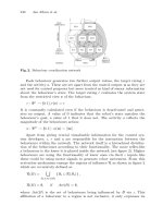
FIGURE 9.1 Microfabricated array of 300 Â 500 mm louver array. The area below the
louvers has been removed using deep reactive ion etch (DRIE). The right picture shows
some of the louvers open, exposing the high emissivity surface below the substrate. (Cour-
tesy: JHU/APL.)
Closed Partially open
0.0 0.2 0.4 0.6 0.8 1.0
Open
FIGURE 9.2 IR emissivity of the MEMS louver array with the louvers closed, partially open,
and open. (Courtesy: JHU/APL.)
Osiander / MEMS and microstructures in Aerospace applications DK3181_c009 Final Proof page 193 1.9.2005 12:07pm
Microsystems in Spacecraft Thermal Control 193
© 2006 by Taylor & Francis Group, LLC
design, JHU/APL, together with NASA/GSFC and Sandia National Laboratory
(SNL), adopted a MEMS shutter design which will be flown on ST5. Fabricated
with SNL’s SUMMIT 5 process, six electrostatic comb drives, using SNL’s high-
performance design, will move an array of shutters, each 150 mm long and 6 mm
wide, to either a gold surface or the silicon substrate and changing the emissivity
from 0.6 (silicon) to < 0.1 (gold). A picture of such an array, 1767 Â 876 mmin
size, is shown in Figure 9.3. Seventy-two of these arrays are on a single die, each
1.265 Â 1.303 cm in size. All arrays on a die are controlled together with a supply
voltage greater than 35 V and negligible current draw. For the shutter, a single
failure may cause a short and stop the entire die from working. In order to prevent
such an issue, each array is connected to the supply bus via a MEMS fuse, which
can be blown with a current of greater than 17 mA. Note that for normal operation,
the current is minimal and the dc leakage current has been determined to be
< 80 mA. A picture of the final radiator assembly is shown in Figure 9.4. Each
radiator, 9 Â 10 in size, contains 6 AlC substrates; which themselves contain six
shutter dies each, adding up to a total of 36 dies on the radiator.
The VEC Instrument consists of two components, the previously described
MEMS Shutter Array (MSA) radiator and the Electronic Control Unit (ECU).
The MSA radiator is physically located on the top deck of the spin-stabilized ST5
spacecraft. The ECU is located within the spacecraft. The MSA radiator can be
operated in both manual and autonomous mode, to automatically evaluate both high
and low emittance states in a given test sequence as well as via ground control. A
1.5 W electrical heater is included in order to provide calibrated measurements of
effective emittance changes. The radiator is located so that it receives minimal solar
exposure. The MSA radiator is thermally isolated from the spacecraft, as the VEC
technologies on this mission are for technology validation only. The thermal
performance associated with opening and closing the shutters is measured by
thermistors that are located on the underside of the MSA radiator chassis.
FIGURE 9.3 Shuttle arrays are on a single die, each 1.265 Â 1.303 cm in size. (Courtesy:
JHU/APL.)
Osiander / MEMS and microstructures in Aerospace applications DK3181_c009 Final Proof page 194 1.9.2005 12:07pm
194 MEMS and Microstructures in Aerospace Applications
© 2006 by Taylor & Francis Group, LLC