Micro Electro Mechanical System Design - James J. Allen Part 3 docx
Bạn đang xem bản rút gọn của tài liệu. Xem và tải ngay bản đầy đủ của tài liệu tại đây (1.18 MB, 30 trang )
40 Micro Electro Mechanical System Design
• Easy to start and stop the etch process
• Repeatable etch process
• Anisotropic etches
• Few particulates
Plasma etching includes a large variety of etch processes and associated
chemistries that involve varying amounts of physical and chemical attack. The
plasma provides a flux of ions, radicals, electrons, and neutral particles to the
surface to be etched. Ions produce physical and chemical attack of the surface,
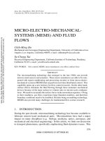
FIGURE 2.21 Directional etching of crystalline silicon.
TABLE 2.6
Common Crystalline Silicon Etchant Selectivity and
Etch Rates
Etchant Etch rate
18HF + 4HNO
3
+ 3Si → 2H
2
SiF
6
+ 4NO + 8H
2
O Nonselective
Si +H
2
O
2
+ 2KOH → K
2
SiO
3
+ 2H
2
{100} 0.14 µm/min
{111} 0.0035 µm/min
SiO
2
0.0014 µm/min
SiN
4
not etched
Ethylene diamine pyrocatechol (EDP) {100} 0.75 µm/min
{111} 0.021 µm/min
SiO
2
0.0002 µm/min
SiN
4
0.0001 µm/min
Tetramethylammonium hydroxide (TMAH) {100} 1.0 µm/min
{111} 0.029 µm/min
SiO
2
0.0002 µm/min
SiN
4
0.0001 µm/min
φ=54.7°
φ
[111]
[100]
SiO
2
mask
© 2005 by Taylor & Francis Group, LLC
Fabrication Processes 41
and the radicals contribute to chemical attack. The sequence of events that occur
in a plasma etch chamber (
Figure 2.23) are listed below:
• Plasma breaks down the feed gases into chemically reactive species.
• Reactive species diffuse to the wafer surface and are adsorbed.
• Surface diffusion of reactive species takes place until they chemically
react.
• Reaction product desorption occurs.
• Reaction products diffuse away from the surface.
• Reaction products are transported out of the chamber
The details and types of etch chemistries involved in plasma etching are varied
and quite complex. This topic is too voluminous to be discussed in detail here,
but a number of excellent references on this subject are available [3,4]. The proper
choice of these chemistries produces various etch rates and selectivity of material
etch rates, which is essential to the integration of processes to produce micro-
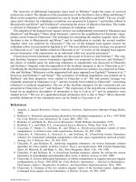
FIGURE 2.22 Boron-doped silicon used to form features or an etch stop.
B B B B B B B B B B B B B B B B B B B B B B B B
Single Crystal Silicon
a. Implant Boron in Single Crystal Silicon wafer
[100]
b. Deposit and Pattern Silicon Dioxide Etch Mask
SiO
2
mask
B B B B B B B B B B B B B B B B B B B B B B B B
[111]
B B B B B B B B B B B B B B B B B B B B B B B B
c. KOH etch
© 2005 by Taylor & Francis Group, LLC
42 Micro Electro Mechanical System Design
electronics or MEMS devices. Fluoride etch chemistries are one of the most
widely studied for silicon etches. Equation 2.6 through Equation 2.8 illustrate
some of the fluoride reactions involved in the etching of silicon, silicon dioxide,
and silicon nitride, respectively. A number of feed gases can produce the free
radicals involved in these reactions.
(2.6)
(2.7)
(2.8)
The anisotropy of the plasma etch can be increased by the formation of
nonvolatile fluorocarbons that deposit on the sidewalls. This process is called
polymerization and is controlled by the ratio of fluoride to carbon in the reactants.
The side wall deposits produced by polymerization can only be removed by
physical ion collisions. Etch products from the resist masking are also involved
in the polymerization.
End point detection of an etch is important in controlling the etch depth or
minimizing the damage to underlying films. This detection is accomplished by
analysis of the etch effluents or spectral analysis of the plasma glow discharge.
Types of plasma etches include reactive ion etching (RIE) and high-density
plasma etching (HDP). RIE etching utilizes a low-pressure plasma. Chlorine (Cl)-
based plasmas are commonly used to etch silicon, GaAs, and Al. RIE etching
may damage the material due to the impacts of the ions; this can be removed by
annealing at high temperatures. HDP etches utilize magnetic and electric fields
FIGURE 2.23 Schematic of a plasma etch chamber.
Si F SiF+ →4
4
*
3 4 2 2 3
2 3 2 4
SiO CF CO CO SiF+ → + +
+
Si N F SiF N
3 4 4 2
12 3 2+ → +*
© 2005 by Taylor & Francis Group, LLC
Fabrication Processes 43
to increase dramatically the distance that free electrons can travel in the plasma.
HDP etches have good selectivity of Si to SiO
2
and resist.
2.5.3 ION MILLING
Ion milling is a purely physical etching process; no chemical reactions are
involved. Ion milling uses noble gases with significant mass such as argon in a
process analogous to sputtering. This process is very isotropic because the ion
impinges the surface nearly vertically. However, the process has an etch rate
selectivity of the material to be etched to the mask material of nearly 1:1 because
the process is purely physical. Ion milling is not widely used for production
applications, and it is generally limited to the smaller wafer sizes (<200 mm).
The etch rates can be increased by increasing the ion densities impacting the
surface through the use of magnetic fields.
2.6 PATTERNING
The ability to pattern deposited layers is an essential capability required in
microelectronics and MEMS processing. Three widely utilized methods of pat-
terning will be discussed: lithography, the lift-off process, and the damascene
process.
Lithography is the mainstream process utilized for patterning in MEMS
processes. Lift-off and damascene are processes used for patterning materials in
which a reliable etch process such as metallization layers or optical coating layers
does not exist. These are frequently required in the postprocessing of MEMS
devices.
The current research and development in patterning for very fine line widths
(<0.35 µm) involve the development of sophisticated tools such as x-ray lithog-
raphy [7] or direct-write E-beam lithography [8]. Microelectronics will need the
capability to pattern features (line widths) of this size in the future in order to
continue development of microelectronic devices of increasing speed and capa-
bility. However, mainstream MEMS technology does not currently require such
fine features, so these methods will not be discussed here.
2.6.1 LITHOGRAPHY
Lithography is the most widely used method to pattern layers in microelectronic
and MEMS processing.
Figure 2.24 is a schematic of a basic lithography system.
The basic components of a photolithographic system include:
• Illumination source
• Shutter
• Mask
• Wafer alignment/support system
• Photosensitive layer (photoresist or “resist”) on a wafer
© 2005 by Taylor & Francis Group, LLC
44 Micro Electro Mechanical System Design
Lithography is the most critical process in microelectronics and MEMS
processes, and the equipment is generally the most costly in a microelectronics
or a MEMS fabrication facility. For example, a microelectronic process will
require 20 or more lithography steps, and a surface micromachine process will
require 10 or more lithography steps. A lithography process step will generally
require application and prebaking of the photoresist to harden the resist; the
exposure of the photoresist in the lithography tool; development of the photoresist;
and a postbake of the photoresist to fully harden the resist to define the feature
accurately. Thus, a lithography step requires several subprocesses that are repeat-
edly performed to fabricate a MEMS or microelectronic device. The other pro-
cessing steps required in a MEMS or microelectonic fabrication may go through
different tools for a specific deposition or a particular type of etch, but lithography
is the common tool that will always be used. Therefore, lithography is the critical
path in the fabrication facility and much attention is paid to the development of
technology and enhancements that can speed this process step.
The performance metrics most important to lithographic processing are res-
olution, registration, and processing throughput. The resolution for optical lithog-
raphy is very closely tied to the wavelength of the illumination source. The
development of lithographic equipment has used ever decreasing wavelength
illumination from the visible spectrum to ultraviolet (UV) and on to the research
and development use of extreme ultraviolet (EUV).
The design of the optical system of the lithographic equipment is very com-
plex, as can be illustrated by the discussion of a few key parameters of the optical
system. The minimum line width, W
min
, capability of the lithographic system can
be expressed by Equation 2.9, which is very similar to the Raleigh criteria [9]
for optical resolution:
FIGURE 2.24 Lithography system schematic.
resist
optical system
mask
shutter
illumination
source
alignment
stage
wafer
© 2005 by Taylor & Francis Group, LLC
Fabrication Processes 45
(2.9)
where
W
min
= minimum line width
K = a measure of the ability of the photoresist to distinguish changes in
intensity
λ = illumination source wavelength
NA = numerical aperture
The numerical aperture defined by Equation 2.10 is a function of the refractive
index, n, of the medium between the objective and wafer and the half angle of
the image, α:
(2.10)
Another optical parameter of interest in the design of the lithographic system
is the depth of focus, σ (Equation 2.11). The depth of focus is an issue in MEMS
fabrication due to the thickness of the films involved and the possible wafer
warpage due to residual stress of the deposited films. Films involved in MEMS
processes can be several microns thick. Patterning of the various layers will give
rise to topographic features on the wafers. When photoresist is spread on a wafer
containing these topographical features or the wafer is warped due to film residual
stress, the lithographic process will attempt to expose the photoresist at various
heights, thus making the depth of focus capability a critical issue.
(2.11)
As can be seen from this limited subset of the optical design parameters, the
optical design is complex and the design parameters interrelated. For example,
to make W
min
smaller, utilizing a smaller wavelength source, λ, and a larger
NA would be beneficial; however, the depth of focus, σ, will be reduced as a
result.
Masks contain the patterns that need to be etched into the material to imple-
ment the MEMS design. The masks can be the same size (1:1) as the patterns to
be transferred and etched into the MEMS material. Depending on the lithographic
system, the masks may be larger than the patterns to be etched into the material.
Masks are typically 1×, 5×, or 10× larger than the patterns to be imaged and
etched. The mask is made of materials (e.g., fused silica) that are transparent at
the illumination wavelength, with the patterns defined by an opaque material
(e.g., chromium) at the illumination wavelength. The mask will need to be very
flat and insensitive to changes in temperature (e.g., small coefficient of thermal
W K
NA
min
≈
λ
NA n= sin α
σ
λ
=
NA
2
© 2005 by Taylor & Francis Group, LLC
46 Micro Electro Mechanical System Design
expansion, α
T
). Contamination control is also an issue in the lithography process.
For example, masks may have a pellicle membrane (Figure 2.25) held above the
patterned area to keep particles off the mask surface and out of the image plane
of the mask to prevent degradation of the lithographic image.
Photoresist is a photosensitive organic compound applied to the wafer surface.
The photoresist consists of three components:
• Resin material is organic material that forms the bulk material of the
photoresist that will affect the durability during subsequent processing
and resolution of the photoresist.
• Photoactive compound is the photosensitive material that determines
the sensitivity of the photoresist (mJ/cm
2
) to the illumination needed
to produce a chemical change.
• Solvent is the component affecting the viscosity of the resist that affects
the application of photoresist, which is generally done by spinning the
wafer and using centrifugal force to spread the photoresist to a uniform
thickness. The solvent in the resist is then removed during the baking
steps to make the material structurally rigid.
FIGURE 2.25 Photomask with pellicle.
© 2005 by Taylor & Francis Group, LLC
Fabrication Processes 47
The lithographic process will transfer the image from the mask to photoresist
on the wafer surface. Two types of photoresist can be used:
• Negative resist. The region of photoresist that has not been exposed to
the illumination will dissolve during the development process and be
removed.
• Positive resist. The region of photoresist that has been exposed to the
illumination will dissolve during the development process and be
removed. Positive resist has the best resolution and is more widely used.
After it is exposed and developed, the photoresist will be used as a physical
mask during subsequent etching processes to transfer the pattern in photoresist
on to the thin film of MEMS material beneath the photoresist. Photoresist is a
key material in the lithographic processing sequence as well as the subsequent
etch steps. It must have a diverse set of properties to enable the definition of the
pattern and also maintain physical integrity during subsequent etching processes.
The aligner is the piece of mechanical equipment that supports the litho-
graphic optical system and mask. It will align the masks relative to target patterns
on the wafer; this will have the effect of aligning the masks and their subsequently
etched patterns on the wafer with the mask and patterns utilized later in the
fabrication sequence. Figure 2.26 shows a typical alignment target, which is
typically specified by the lithographic system manufacturer. Two general types
of aligners will be considered here:
• Contact/proximity aligner. The mask is held in contact or close prox-
imity (a few microns) of the photoresist surface. These aligners utilize
1× masks and do not have pellicles due to the lack of available clear-
ance between the mask and photoresist. The contact aligner actually
FIGURE 2.26 Example of a lithographic alignment target.
© 2005 by Taylor & Francis Group, LLC
48 Micro Electro Mechanical System Design
presses the mask under pressure against the photoresist, which will
have the effect of degrading the mask under repeated use. This category
of aligner is the least expensive, and has the lowest resolution capa-
bility. These aligners are generally used for research or limited pro-
duction applications.
• Projection aligner. The mask and wafer are separated as dictated by
the design of the optical system. This class of aligner can have high
resolution that is only limited by optical system performance. These
systems can be very expensive and are utilized in high-volume
manufacturing.
2.6.2 LIFT-OFF PROCESS
Lift-off is a patterning process frequently used in MEMS for patterning materials
that do not possess a reliable process to etch them (e.g., noble metals). The lift-
off process is accomplished via the use of an intermediate layer and deposition
process, which has poor step coverage. Figure 2.27 is a schematic of a lift-off
process that will deposit and pattern a material on a substrate or underlying layer.
This process involves the following steps:
• Deposit and pattern a thick intermediate layer of a material that is easy
to remove (e.g., SiO
2
or photoresist) and that will have a slightly
reentrant profile.
• Deposit a layer of the material to be patterned utilizing a process that
has poor step coverage (e.g., evaporation). The material thickness
should be a fraction of the intermediate layer thickness.
FIGURE 2.27 Lift-off process schematic.
patterned SiO
2
/resist
evaporated metal layer
substrate
a. Evaporated metal layer on a patterned SiO
2
or resist layer
b. Strip the SiO
2
or resist layer leaving the metal on the substrate
© 2005 by Taylor & Francis Group, LLC
Fabrication Processes 49
• Removal of the intermediate layer will cause the metal layer to fracture
due to the stress concentration in the region of poor step coverage.
Alternatively, the lift-off process can involve a process that will explicitly
form an undercut metal layer and not rely on the metal layer to fracture at the
step. Figure 2.28 is a schematic of a process that will involve the explicit devel-
opment of an undercut region:
• Deposit thick intermediate layer of a material (e.g., SiO
2
).
• Deposit and pattern a layer of photoresist.
• Undercut the photoresist with a process such as wet chemical etching.
• Deposit a layer of the material to be patterned utilizing a process that
has poor step coverage (e.g., evaporation). The material thickness
should be a fraction of the photoresist and oxide layers.
• Remove the SiO
2
and photoresist, which will leave only the patterned
metal layer.
FIGURE 2.28 Lift-off process schematic with undercut metal layer.
resist
substrate
(a) Substrate with an oxide layer and patterned resis
t
(b) Wet etch oxide layer to undercut the resist layer
(c) Evaporate metal layer
metal
(d) Strip resist
(e) Remove oxide
SiO
2
© 2005 by Taylor & Francis Group, LLC
50 Micro Electro Mechanical System Design
2.6.3 DAMASCENE PROCESS
The damascene process is an ancient process first developed in the Middle East
[10] and utilized to inlay elaborate patterns on metal swords with various soft
metals that could be easily polished. The concept of the damascene process
(Figure 2.29) starts with forming a mold upon a substrate, depositing a metal
which fills the mold and covers the surface. The surface is then polished so that
only the material within the mold remains. Then the mold material can optionally
be removed. The damascene process like the lift-off process is used to pattern
materials that do not possess a reliable method of etching. For MEMS and
microelectronics, these processes are used for patterning metal layers (e.g.,
copper, gold, etc.). The method frequently utilized for polishing the metal layer
back to the mold is chemical mechanical polishing, which is discussed later in
this chapter.
2.7 WAFER BONDING
Wafer bonding processes are used in packaging and to build up more complex
structures. For example, bulk micromachined devices can be assembled into more
complex structures by bonding multiple wafers together. Also, microfluidic chan-
nels can be formed by DRIE etching the channel in one wafer and bonding a
wafer to seal the channel. The two categories of wafer bonding processes that
will be discussed are silicon fusion bonding and anodic (electrostatic) bonding.
FIGURE 2.29 Damascene process schematic.
© 2005 by Taylor & Francis Group, LLC
Fabrication Processes 51
The choice of bonding process will be influenced by the thermal budget of the
devices and materials involved.
2.7.1 SILICON FUSION BONDING
At room temperature, two highly polished flat silicon wafers brought into contact
will bond. The mechanism is believed to be hydrogen bonds between the surfaces.
The bond can be converted into a stronger Si–O–Si bond at an elevated temper-
ature (>800˚C). The main concern with this bonding technique is voids in the
bonded wafer due to surface defects, residues, and particulate on the surface. The
processing sequence for silicon fusion bonding will generally include the follow-
ing steps:
• Polishing of the wafer surfaces to be bonded
• Wafer surface wet cleaning processes to make the bond surface hydro-
philic, which will facilitate the bonding mechanism
• Wafer surface inspection
• Precise alignment of bond surfaces in a clean environment
• Annealing of the bonded wafers
Other silicon-based materials such as polycrystalline silicon (polysilicon),
silicon dioxide, and silicon nitride can be similarly bonded. However, yield of
the bonded wafers due to voids will increase due to the different mechanical
properties of the wafers.
2.7.2 ANODIC BONDING
Anodic bonding is an electrostatic bonding technique for glass to silicon wafers
or silicon wafers with a thin silicon dioxide layer between the wafers. Anodic
bonding utilizes a heated chuck with an electrode capable of applying a DC
voltage of up to 200 V. Pressure may be optionally applied to facilitate the bonding
process.
Figure 2.30 is a schematic of an anodic bonding process.
2.8 ANNEALING
Annealing is a process of elevating materials to a high temperature to achieve
one of the following effects:
• Reduction of residual stresses in a material. The deposition process
temperature will greatly influence the residual stress in a deposited
film. A way to reduce the film residual stress is to anneal the film at
a high temperature for a length of time (e.g., polysilicon residual stress
can be reduced by annealing at >1100°C for several hours in an inert
atmosphere, N
2
, which minimizes oxidation).
• Activation of dopants. When dopants are implanted or diffused into a
material to create active electronic devices or piezoresistors, the dopants
© 2005 by Taylor & Francis Group, LLC
52 Micro Electro Mechanical System Design
are activated by an anneal process. This process facilitates the dopants’
movement to an appropriate location within the material lattice struc-
ture. An anneal temperature of >600°C is typical for this application
• Healing of material damage. Implantation of dopants into a material
will cause physical damage to the material through dislocations of the
material atoms. The material damage is healed by annealing the mate-
rial at an elevated temperature (e.g., >600°C).
• Annealing bonded wafers to modify the wafer bond mechanism. Sili-
con to silicon wafer bonds are initially hydrogen bonds that are trans-
formed to a Si–O–Si bond through an annealing step that improves
the wafer bond strength. An anneal temperature of >800°C is typical
of this application.
Several anneal process issues are of concern, depending upon the application:
• Thermal stresses, particularly when dissimilar materials are involved
• Doping profile perturbation at elevated temperatures
• Melting of metal layers, which generally occurs at greater than 450°C
Annealing can be accomplished via an isothermal process in which the
material is exposed to the elevated temperature over a long period of time. The
isothermal annealing processes generally require a thermal controlled volume
with a controlled atmosphere.
Rapid thermal annealing processes that anneal only a small distance into the
material exist. This process will minimize doping profile perturbations and melt-
ing of metal layers within a device. This localized rapidly varying thermal cycling
can be achieved within a fast ramp furnace, which can achieve thermal transients
on the order of 75°C/min. A more rapid thermal transient can be achieved by
moving the wafer within a furnace that has thermal gradients designed into the
equipment.
Figure 2.31 is a schematic of a rapid thermal anneal furnace in which
FIGURE 2.30 Anodic bonding schematic.
hydrated surfaces
glass wafer
silicon wafer
heater
V
(a) Silicon wafers with hydrated surfaces.
(b) Silicon wafers in contact and anneal.
© 2005 by Taylor & Francis Group, LLC
Fabrication Processes 53
the wafer temperature is controlled via an elevator within the furnace. Thermal
transients on the order of 100°C/sec can be achieved with this type of system.
2.9 CHEMICAL MECHANICAL POLISHING (CMP)
Chemical mechanical polishing (CMP) is a process originally developed in the
microelectronics industry to planarize the layers of interconnect. CMP has also
been adapted to MEMS processing in surface micromachining (see Figure 2.32).
CMP has become essential to MEMS fabrication to remove the topography
formed due to the repeated deposition, patterning, and etching of multiple thick
film of material typical in MEMS surface micromachine processes. The topog-
raphy generated in the MEMS processes make patterning with lithographic meth-
ods difficult due to depth of focus issues and poor photoresist coverage over the
uneven surface. The topography also makes the design difficult as well. Figure
2.32 shows a comparison of a MEMS layer in a surface micromachine process
with and without CMP in the process.
In
Figure 2.33, CMP utilizes a slurry of silica particles and a dilute etching
agent applied between the wafer and a pad that is mechanically moved (i.e., a
combination of rotation and linear motion). The removal rate, typically on the
order of 1000s of angstroms per minute, is a function of the pad pressure, relative
velocity, and slurry chemistry. For surface micromachining processes, CMP can
be applied to the sacrificial layers so that the structural layer deposited on top
will not have topography. CMP can also be used in the damascene process
discussed previously to polish the metal layer back to the mold.
FIGURE 2.31 Rapid thermal anneal furnace utilizing a wafer elevator to control the
temperature transient.
Heater section
Cool gas inlet
Gas outlet
© 2005 by Taylor & Francis Group, LLC
54 Micro Electro Mechanical System Design
2.10 MATERIAL DOPING
Dopants are impurities intentionally added to a semiconductor that can achieve
several objectives. Active electronic devices are produced by adding dopants to
a semiconductor material to create the necessary n- and p-junctions. Piezore-
sistors can be used in sensing applications and are created by doping a portion
of a semiconductor material located in a region of high strain. Also, because
doped silicon has different etch characteristics than single-crystal silicon, a
doped layer can be used as an etch stop; this will facilitate bulk micromachining
manufacture.
Figure 2.34 is a two-dimensional representation of a silicon lattice structure
with a doping material included in the lattice. Silicon is in group IV of the
periodic table and has four electrons in its outer shell; it shares these with four
adjacent atoms to form a three-dimensional lattice structure. Covalent bonding
is the sharing of electrons in the outer shell. For pure single-crystal silicon, all
of the electrons in the outer shell of the silicon atoms are shared, thus producing
a silicon crystal with no free electrons. If the silicon lattice has a small amount
of a dopant, a free electron or a hole can be produced. Figure 2.34a shows
silicon doped with phosphorus, a group V element with five electrons in the
FIGURE 2.32 SUMMiT (Sandia ultraplanar multilevel MEMS technology) polysili-
con layer with and without CMP processing.
FIGURE 2.33 Schematic of a chemical mechanical polishing system.
Linkage
arm
Overhang
(a) Example of a conformable Layer (b) Example of topography removed by
Chemical Mechanical Polishing
Hub
Gear
Planarized
linkage arm
Gear
20 µm
Rotation
Down Force
Carrier
Carrier Insert
Wafer
Pad
Platen
Slurry
© 2005 by Taylor & Francis Group, LLC
Fabrication Processes 55
outer shell. This will produce a free electron in the lattice and produce what is
referred to as an n-type semiconductor. Similarly, a silicon lattice doped with
a group III element, such as boron (with three electrons in the outer shell), will
produce an unfulfilled covalent bond in the structure or a hole. This is a p-type
semiconductor. Table 2.7 is a short list of the group III, IV, and V elements
commonly used.
Two types of processes are utilized to introduce the dopants into a semicon-
ductor material: diffusion and implantation. A diffusion will place the source
material for the dopant atoms on the surface of the semiconductor material and
allow the dopants to diffuse into the semiconductor under elevated temperature.
Implantation will use a particle accelerator to implant the dopant atoms physically
into the semiconductor. As a result of this physical implantation of the dopant
atoms, the semiconductor lattice structure is damaged. The implant damage is
then healed and the dopants activated via an anneal process step.
FIGURE 2.34 A two-dimensional schematic of a silicon lattice doped with phosphorous
and boron to produce an n-type and a p-type semiconductor, respectively.
TABLE 2.7
Group III, IV, and V Elements Commonly Used
in Semiconductors
Group III
(three valance
electrons-acceptors)
Group IV
(four valance
electrons)
Group III
(five valance
electrons-donors)
Boron (B) Silicon (Si) Phosphorus (P)
Aluminum (Al) Arsenic (As)
Gallium (Ga) Antimony (Sb)
Indium (In)
( )
( )
© 2005 by Taylor & Francis Group, LLC
56 Micro Electro Mechanical System Design
2.10.1 DIFFUSION
The diffusion process is performed by placing the source material for the dopant
atoms on the surface of a wafer and allowing the dopant atoms to diffuse into
the semiconductor wafer under elevated temperature. Frick’s law provides a
mathematical model of the diffusion process (Equation 2.12), which is illustrated
in a one-dimensional example in Figure 2.35.
(2.12)
where
C = concentration of dopant atoms as a function of space and time
D = diffusion coefficient, which depends upon the dopant and condition
of the diffusion process, such as temperature
The diffusion coefficient is the proportionality constant between the dopant
atom flux across a surface, J, and the rate of change in dopant atom concentration
across that interface, as shown in Equation 2.13. The negative sign indicates that
the material will diffuse to decrease the concentration:
(2.13)
Frick’s law is a boundary value problem that can be solved analytically for
the one-dimensional case to yield solutions that will correspond to physical
implementations of the diffusion process used to dope semiconductors. Two
instructive solutions of Frick’s law will be examined.
FIGURE 2.35 One dimensional schematic of Frick’s laws.
J
2
∂
∂
= ∇
C
t
D C
2
J D
C
x
= −
∂
∂
© 2005 by Taylor & Francis Group, LLC
Fabrication Processes 57
Case 1. In this case, the dopants constantly arrive at the surface of the
wafer to maintain a constant dopant concentration, C
s
, on the wafer surface
(Equation 2.14). The dopant concentration deep within the wafer is 0, as shown
in Equation 2.15:
(2.14)
(2.15)
Equation 2.14 and Equation 2.15 are the problem boundary conditions. The initial
condition at t = 0 is that the concentration is zero throughout the domain:
(2.16)
Frick’s equation with these boundary and initial conditions can be solved to
yield, Equation 2.17. is called the diffusion length — a quantity that appears
in the analytical solutions of Frick’s equations. The solution of Frick’s equation
also involves the complementary error function, which is tabulated in a number
of references [11].
Figure 2.36a plots this solution of Frick’s equation, which
shows the dopant concentration increasing within the wafer and penetrating
deeper as time increases. The concentration remains constant at the wafer surface.
(2.17)
Case 2. In this situation, a fixed amount of dopant, Q, has been initially
introduced to the wafer, as shown in Equation 2.18. The initial distribution is
approximated as a delta function at x = 0, and the initial concentration elsewhere
in the wafer is 0 (Equation 2.19). There are two boundary conditions for this
case. For the surface, x = 0, no additional dopants are added (Equation 2.20).
This boundary condition is obtained from Frick’s first law, Equation 2.13, which
relates the dopant flux at a surface, J, and the rate of change of the concentration
at the surface. The second boundary condition assumes that the wafer is thick;
therefore, at x = ∞, the concentration is zero (Equation 2.21).
(2.18)
(2.19)
(2.20)
C x t C( , )= =0
C x t( , )= ∞ = 0
C x t( , )= =0 0
Dt
C x t C erfc
x
Dt
s
( , ) =
2
C x t dx Q( , )
0
∞
∫
= = constant
C x t x( , ) ,= = ≠0 0 0
J x t
dC x t
dx
( , )
( , )
= =
=
=0
0
0
© 2005 by Taylor & Francis Group, LLC
58 Micro Electro Mechanical System Design
FIGURE 2.36 Solution of Frick’s equation solutions for case 1 and case 2.
10
0
10
1
10
0
0 0.5 1
Depth–micron
(a) Case 1
(b) Case 2
= 0.1
Depth–micron
Concentration/Initial Fixed Impurity Concentration
1.5 2
0 0.5 1 1.5 2
2.5
Concentration/Surface Concentration
2.5
= 0.1
= 0.2
= 0.3
= 0.2
= 0.3
D
t
D
t
D
t
D
t
D
t
D
t
© 2005 by Taylor & Francis Group, LLC
Fabrication Processes 59
(2.21)
The analytical solution for Frick’s law with these initial and boundary con-
ditions is a Gaussian function shown in Equation 2.22. The solution for this case
is illustrated in
Figure 2.36, which shows that the slope of the concentration is
zero at x = 0 because there is no dopant flux at the x = 0 surface. Also, the
concentration at the surface x = 0 decreases with time, which can be calculated
from Equation 2.22:
(2.22)
The implementation of the diffusion process can involve a gaseous, liquid,
or solid source of dopants (Table 2.8). The wafer can be masked to allow the
dopants to diffuse into selected locations (
Figure 2.37). Silicon dioxide can be
used for the masking material in the diffusion process because the diffusion
coefficient for silicon dioxide is approximately 10
4
less than the diffusion coef-
ficient of silicon at typical processing temperatures (
Table 2.9). Two mechanisms
of diffusion occur, as illustrated in
Figure 2.38. Interstitial diffusion is the mech-
anism through which atoms (e.g., H
2
, He, Na, O
2
) that do not strongly interact
with silicon diffuse through the silicon lattice. Lattice vacancy exchange is the
mechanism used by the important group III and V dopants.
TABLE 2.8
Phosphorus, Boron, and Arsenic Chemical Sources for Diffusion
Dopant
Sources
Gaseous Liquid Solid
Arsenic AsH
3
.AsF
3
Arsenosilica AlAsO
4
Phosphorus PH
3
,PF
3
POCl
3
, phosphosilica NH
4
H
2
PO
4
, (NH
4
)
2
H
2
PO
4
Boron B
2
H
6
, BF
3
, BCl
3
BBr
3
, (CH
3
O)
3
B, borosilica BN
FIGURE 2.37 Diffusion with a silicon dioxide mask.
C x t( , )= ∞ = 0
C x t
Q
Dt
e
x
Dt
( , ) =
−
π
2
4
© 2005 by Taylor & Francis Group, LLC
60 Micro Electro Mechanical System Design
2.10.2 IMPLANT
Implantation is the most common method for doping a semiconductor used today.
Implantation utilizes a particle accelerator to implant the ions of up to 200 keV
physically into the wafer material. This physical implantation process will damage
the lattice material, which is subsequently annealed to remove the damage and
allow the implanted ion to fill vacancies in the silicon lattice (i.e., activate the
dopants). Implantation is the most frequently used method of doping material
because of several significant advantages:
• Precise dopant control
• Less lateral diffusion
• Variety of doping profiles attainable (
Figure 2.39)
Figure 2.40 shows a schematic of an ion implantation system. The principal
components are the ion source; magnetic analysis system; resolving aperture;
accelerator; beam control system; mask; and Faraday cup. The ion source pro-
duces a flux of ions that is sent through the magnetic analysis system to select
the desired ions, which produce a collumated beam after they pass through the
resolving aperture. The ions are then accelerated to the desired energy level by
the accelerator and the beam position controlled and scanned by the beam control
system. The ion dose is measured by the Faraday cup where the wafer is posi-
TABLE 2.9
Phosphorus and Boron Diffusion Coefficients
in Silicon and Silicon Dioxide
Material D
Si
(cm
2
/s) (cm
2
/s)
B 2 × 10
–15
3 × 10
–19
P 1 × 10
–14
1 × 10
–18
FIGURE 2.38 Diffusion mechanisms.
D
SiO
2
(a) Interstitial Diffusion (b) Vacancy Diffusion
© 2005 by Taylor & Francis Group, LLC
Fabrication Processes 61
tioned. This type of implantation system can deliver a precise and pure dose of
dopants to the wafer.
2.11 SUMMARY
This chapter provided an overview of the individual processes that can be used
in MEMS fabrication technology. Most of the fabrication processes that have
been presented are an outgrowth of the microelectronics industry. The fabrication
processes can be combined to form a fabrication sequence or technology. MEMS
technologies are discussed in the next chapter.
The fabrication process for starting material or substrates was presented in
Section 2.2. MEMS fabrication frequently involves the deposition, patterning,
and etching of a material upon a substrate (i.e., an additive process) or etching
FIGURE 2.39 Comparison of doping profiles for diffusion and implantation.
FIGURE 2.40 Schematic of an implantation system.
I
© 2005 by Taylor & Francis Group, LLC
62 Micro Electro Mechanical System Design
the substrate material (i.e., a subtractive process). The fabrication methods were
presented for a single-crystal substrate (i.e., Czochralski growth, float zone) as
well as for silicon on insulator (SOI) substrates (i.e., SIMOX, Unibond).
A fundamental process sequence will generally involve deposition, pattern-
ing, and etching. The deposition processes of physical vapor deposition (PVD)
and chemical vapor deposition (CVD) and their variants were presented. The
selection of deposition process and its parameters will control characteristics of
the deposited film such as residual stress, and conformal or nonconformal layer.
These characteristics can be very important to subsequent MEMS fabrication
processes or the MEMS device.
Etching processes can be isotropic or anisotropic in nature. The selection of
the specific etch process and material is important in determining these charac-
teristics. The wet chemical etching, plasma etching, and ion milling processes
were discussed. To a large degree, patterning is performed via lithographic meth-
ods. However, for materials that do not have a viable etch process, the lift-off or
damascene process can be utilized.
A number of other processes used to achieve specific effects were presented.
Annealing is utilized in a manner similar to macroscale manufacturing to relieve
residual stresses. Chemical mechanical polishing (CMP) is used to remove topog-
raphy in films or for patterning a film in a damascene process. The doping of a
material for electrical purposes can be achieved by diffusion or implantation
processes. Wafer bonding is a process that can be used to produce a specific
structure for packaging or a MEMS device.
QUESTIONS
1. List the type of atomic bonds and describe them. Give an example of
a material utilizing each type of bond.
2. What are Van der Waals forces and when are they important?
3. What are the three types of material structure?
4. Name and sketch the common variants of the cubic lattice structure.
5. Sketch a face-centered cubic lattice and the (1 0 0) plane. What is the
plane equivalent to the (1 0 0) plane? Repeat for the (1 1 1) plane.
6. Give four examples of lattice defects. What is activation energy?
7. What is the maximum pull rate of a silicon seed crystal from the molten
bath due to the heat transfer of the latent heat of fusion? (Hint: refer
to Equation 2.1.) What are the parameters that could be used to control
the boule diameter?
8. What are the majority carriers for single-crystal silicon doped with
boron?
9. What are the dopants that could be used in an n-type silicon wafer?
10. What is meant by a conformable film? What process could deposit a
conformable film?
11. What is meant by a nonconformable film? What process could be used
to deposit a nonconformable film? Why would one want to do this?
© 2005 by Taylor & Francis Group, LLC
Fabrication Processes 63
12. What is meant by step coverage? Give an example of why this is
important.
13. What etchants can anisotropically etch single-crystal silicon? What
crystal direction has the fastest etch rate? What crystal direction has
the smallest etch rate?
14. What material could be used as a mask for a KOH etch of single-crystal
silicon?
15. Describe the difference between contact and optical lithography. Which
could produce a smaller dimension pattern in the photoresist?
16. What are the elements of a photoresist? Describe how photoresist is
utilized in the patterning process.
17. Why would one use a lift-off or damascene process?
18. Describe the lift-off and damascene processes and their similarities.
19. Describe the annealing process for polysilicon. List two reasons for
annealing a deposited film.
20. Why does the implant process provide a more accurate definition of
the dopant profile and region?
REFERENCES
1. G.K. Teal, Single crystals of germanium and silicon — basic to the transistor and
the integrated circuit, IEEE Trans. Electron. Dev. ED-23, 621, 1976.
2. W.R. Grove, On the electrochemical polarity of gases, Philos. Trans. Faraday Soc.
87, 1852.
3. R.A. Morgan, Plasma Etching in Semiconductor Fabrication, Elsevier, Amster-
dam, 1985.
4. D.M. Manos and D.L. Flamm, Plasma Etching, an Introduction, Academic Press,
Boston, 1989.
5. R.A. Morgan, VCSEL — a new twist in semiconductor-lasers, Photonics Spectra,
24(12), 89, 1990.
6. M.A. Michalicek, V.M. Bright, Flip-chip fabrication of advanced micromirror
arrays, Sensors Actuators A, 95, 152–157, 2002.
7. S. Ohki, S. Ishihara, An overview of x-ray lithography, Microelectron. Eng.,
30(1–4), 171–178, January 1996.
8. R. DeJule, E-beam lithography, the debate continues, Semiconductor Int., 19, 85,
1996.
9. M.V. Klein, Optics, John Wiley & Sons, New York, 1970.
10. J.D. Verhoeven, The mystery of Damascus blades, Sci. Am., 74–79, January 2001.
11. M. Abramowitz, I.A. Stegun, Handbook of Mathematical Functions with Formu-
las, Graphs, and Mathematical Table, National Bureau of Standards Applied
Mathematics Series 55, June 1964, 10th printing, December 1972.
© 2005 by Taylor & Francis Group, LLC
65
3
MEMS Technologies
For all but the simplest of applications, the large assortment of individual fabri-
cation processes discussed in
Chapter 2 needs to be combined synergistically to
form a technology that can produce useful MEMS devices. Three dominant
MEMS fabrication technologies — philosophically different in their approach —
are currently in use:
• LIGA (Lithographie, Galvanoformung, Abformung)
• Bulk micromachining
• Sacrificial surface micromachining
Figure 3.1 illustrates the basic concepts of each of the three fabrication
approaches. Bulk micromachining and sacrificial surface micromachining are
most frequently silicon based and are generally very synergistic to the microelec-
tronics industry because they tend to use common tool sets.
Bulk micromachining (BMM) utilizes wet- or dry-etch processes to produce
an isotropic or anisotropic etch profile in a material. Bulk micromachining can
create large MEMS structures (tens of microns to a millimeter thick), which can
be used for applications such as inertial sensing or fluid flow channels. Commer-
cial applications of bulk micromachining have been available since the 1970s.
These applications include pressure sensors, inertial sensors, and ink-jet nozzles.
Sacrificial surface micromachining (SSM) is a direct outgrowth of the fabri-
cation processes of the microelectronics industry. SSM technology also has a
path toward the integration of electronics with the MEMS structures, which will
facilitate control or sensing functions. SMM technology has had several com-
mercial successes in the last decade (
Figure 3.2), including optical mirror arrays
and inertial sensors. Both of these applications include integrated microelectron-
ics for sensing and control functions. This technology is generally limited to
individual film thicknesses of 2 to 6 µm with an overall device thickness of <15
µm. The resulting devices are assembled as they are fabricated, thus relieving a
difficult task; this gives SSM technology a large advantage for applications
involving large arrays of devices.
LIGA technology was first demonstrated in the1980s. This technology can
fabricate devices with small critical dimensions and high aspect ratios (i.e.,
thickness/width) with electroplated metallic materials. The metallic LIGA parts
can be used directly or as a die for an injection molding process to produce plastic
parts. This gives this technology the advantage in applications requiring a broad
© 2005 by Taylor & Francis Group, LLC