Microengineering MEMs and Interfacing - Danny Banks Part 4 pot
Bạn đang xem bản rút gọn của tài liệu. Xem và tải ngay bản đầy đủ của tài liệu tại đây (601.69 KB, 14 trang )
40
Microengineering, MEMS, and Interfacing: A Practical Guide
in a rotating clamp is brought up to the surface of the melt. As the seed crystal
is slowly withdrawn from the crucible, it draws out the cooling silicon with it.
As this solidifies, it takes on the same crystal structure as that of the seed crystal.
The result is a cylindrical bar or ingot (Figure 2.4) of up to 12-in. (300-mm)
diameter. (Note: wafer diameters are often specified in imperial units).
2.4 DOPING
Impurities are normally introduced into the silicon melt to dope it as either a
p-type
or
n-type
semiconductor. In the case of
p-type
semiconductors, a group III
element, boron (B), is introduced. Group V elements, phosphorous (P) or arsenic
(As), are used to form
n-type
silicon. The introduction of a small proportion of
B impurities into the silicon reduces the number of electrons available from
carrying current, whereas n-type dopants such as P or As increase the number of
available electrons. The physical effects induced by this processing form the basis
of electronic components such as diodes and transistors.
FIGURE 2.4
Silicon bar. (Image courtesy of Compart Technology Ltd, Peterborough,
U.K., www
.compart-tech.co.uk and Forest Software, Peterborough, U.K., www.forestsoft-
ware.co.uk.)
Dopant Levels
Silicon is referred to as p-type, p
+
, or p
++
(also n-type, n, or n) silicon, depending
on the degree of doping. Silicon wafers will be either n- or p-type. Electronic
devices will usually be constructed of n-type and p-type layers, with more
heavily doped n or p
+
regions being used to connect to conductive intercon-
nects. Heavily doped n and p
++
silicon is highly conductive and not normally
used in devices, except as short-conducting tracks.
DK3182_C002.fm Page 40 Friday, January 13, 2006 10:58 AM
Copyright © 2006 Taylor & Francis Group, LLC
Silicon Micromachining
41
In the fabrication of both electronic circuits and MEMS, it is desirable to introduce
controlled levels of impurities into the silicon substrate in specific areas. The engineer
has two basic options for achieving this: thermal diffusion and ion implantation.
2.4.1 T
HERMAL
D
IFFUSION
This is normally carried out in a furnace at temperatures in excess of 1000
°
C.
As such, it must be one of the earliest processes engaged in or the temperatures
will damage (melt) subsequent parts of the structure. The process is fairly straight-
forward in concept and consists of the following:
• A layer of high-quality silicon dioxide (thermal oxide, or densified
chemical vapor deposition [CVD] oxide) is deposited and patterned to
form a mask (the photoresist being stripped).
• The wafer is brought into contact with ceramic tiles rich in the appro-
priate impurity (a diffusion source). A doped spin-on glass can also be
used if deep diffusion of high impurity concentration is not required.
• The wafer and diffusion source are introduced into a furnace heated
to sufficient temperature for an appropriate time. (For example, at
temperatures of 1175
°
C an 8-h diffusion will result in > 8-
µ
m-thick
structures released by concentration-dependent etching. It will be
necessary to use an oxide mask of at least 1-
µ
m thickness in such
cases.)
• Following diffusion, the mask needs to be stripped. This is normally
a difficult process as the material will have been affected by the dif-
fusion; a wet etch may not suffice, and dry-etching processes (discussed
later in this chapter) may have to be employed.
Note that diffusion is an anisotropic process — the impurities diffuse laterally
under the mask as well as vertically into the substrate. Diffusion profiles are,
therefore, somewhat rounded.
2.4.2 I
ON
I
MPLANTATION
In contrast to thermal diffusion, ion implantation is a very precise and isotropic
process. Charged ions of the chosen impurity are accelerated towards the substrate.
They will reach a depth that can be determined by the momentum that the ion gains
through acceleration. Note that ions with a stronger charge can be accelerated more
rapidly towards the target and, thus, implanted to greater depths. Nonetheless, ion
implantation normally targets only the top 1
µ
m of the substrate. It is possible to
implant ions to a depth of 4
µ
m into the surface of the substrate, but this can leave
it mildly radioactive (it will have to be subjected to a cooling period).
Ion implantation has several advantages over thermal diffusion, such as the
following:
• It is carried out at room temperature (but the substrate will get hot
unless mounted on a cooled chuck).
DK3182_C002.fm Page 41 Friday, January 13, 2006 10:58 AM
Copyright © 2006 Taylor & Francis Group, LLC
42
Microengineering, MEMS, and Interfacing: A Practical Guide
• It is isotropic.
• It can be used with far more elements than thermal diffusion (oxygen
can be implanted, for instance, to form an insulating layer beneath the
surface of the wafer).
One application of ion implantation in electronics is to create self-aligned
gates on transistors. This effectively utilizes part of the electrical structure of the
transistor as the mask (see Figure 2.7). Ion implantation is not, however, a magical
process by which the impurities simply appear in their targeted locations. When
passing through the wafer, there is a chance that ions will cause damage to the
crystal lattice on the way.
2.5 WAFER SPECIFICATIONS
The first thing to consider when ordering the wafer is the dopant and the degree
of doping required. This will normally be done by specifying the resistivity of
the material — for example, p-type (boron), 10 to 30
Ω
cm.
Silicon ingots are sawn into individual wafers. In addition to the diameter of
the resulting wafer, the thickness, crystal orientation, and flats should be specified.
Wafers are supplied with diameters of 2, 4, 6, 8, or even 12 in. (50, 100, 150,
200, or 300 mm). Wafers of 2-in. diameters and the equipment required to process
them are becoming rare, except for wafers composed enpotic materials. At the time
of writing, 12-in. wafers are only available in the most advanced IC fabs, and
most MEMS work is performed on 4- and 6-in. wafers.
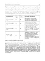
Wafer suppliers will normally supply wafers with what are regarded as opti-
mal thickness — around 525
µ
m for 4- or 6-in. wafers. Thicker wafers waste
silicon, and thinner wafers stand a greater chance of breaking during processing.
It is possible, however, to specify wafers from several millimeters thick to about
10
µ
m thick (Figure 2.5). Very thin wafers are flexible. During processing these
will need to be bonded to a thicker supporting wafer. Very thin wafers are
produced by grinding and chemical–mechanical polishing
of thicker wafers. Note
that the thickness will vary across the wafer because of the natural variations in
the mechanical machining process.
Crystal orientation is specified as the plane along which the ingot is cut, and
tolerance may also be specified. It is normal to grind flats on the sides of the
wafer (see Figure 2.5a). These are specified by the purchaser (e.g., 4-in diameter
(100) wafer with one (110) flat), although there is a loose convention that p-type
wafers have one flat ground and n-type wafers have two. These flats are useful
for aligning the wafer for anisotropic etching, but it should be recalled that they
are mechanically produced and will not align exactly to the crystal plane.
Finally, single- or double-sided polishing, as appropriate, should be specified.
If photolithography is to be performed on both sides of the wafer, then it is
necessary to specify double-sided polishing.
Further refinements may be added to the specification. Silicon-on-insulator
(SOI) wafers are becoming increasingly popular for MEMS applications. These
DK3182_C002.fm Page 42 Friday, January 13, 2006 10:58 AM
Copyright © 2006 Taylor & Francis Group, LLC
44
Microengineering, MEMS, and Interfacing: A Practical Guide
which provides a device-quality surface for circuit fabrication. Silicon dioxide,
silicon nitride, and aluminum films are also commonly provided on request.
Wafer suppliers are also normally able to supply glass wafers (Figure 2.6),
which are also commonly used for MEMS devices, III–V (three–five) semicon-
ductor wafers (i.e., gallium arsenide, or GaAs, which is used for RF, optical, and
high-frequency electronic circuits and, less frequently, for MEMS), sapphire
wafers, and other unusual materials. Some can also supply other shapes in silicon,
such as cylinders, etc.
One final point to recall is that a very thin
native
oxide layer forms on silicon
when exposed to air. This can be stripped by dipping the wafers in a wet oxide
etch prior to processing, but for critical processes, it may be necessary to perform
a sequence of processing steps in an evacuated chamber without breaking the
vacuum, for which special equipment is required.
FIGURE 2.6
Machined glass wafers. (Image courtesy of Compart Technology Ltd., Peter-
borough, U.K., www
.compart-tech.co.uk and Forest Software, Peterborough, U.K.,
www
.forestsoftware.co.uk.)
Specifying the Wafer
The specifications for a wafer are as follows:
• Dopant — impurity and resistivity
• Diameter, thickness
• Orientation, flats
• Polishing
• Special requirements (e.g., SOI, thin-film deposition)
Remember to specify tolerances to critical parameters.
DK3182_C002.fm Page 44 Friday, January 13, 2006 10:58 AM
Copyright © 2006 Taylor & Francis Group, LLC
46
Microengineering, MEMS, and Interfacing: A Practical Guide
• Equipment may be contaminated if used for the deposition of different
materials.
• Deposited films will often be under mechanical stress.
• Deposited films must adhere (usually by forming strong [covalent]
chemical bonds).
• Different materials have different melting points (i.e., high-temperature
processes cannot be carried out after depositing a material of low
melting point).
• Different materials will have different coefficients of thermal expansion
(this may cause cracking, wrinkling, or delamination during fabrication).
• Some deposition processes may coat all exposed surfaces (i.e., be
conformal); others may not coat vertical sidewalls at all (this being
described as the degree of “step coverage”).
Because the properties of the deposited material are so dependent on the
deposition process, it is common to use both the name of the process and the name
of the material together; thus: LTO, meaning low-temperature oxide, aka LPCVD
oxide, is a film of silicon dioxide deposited by the low-pressure chemical vapor
deposition (CVD) technique. Additional comments on thin-film materials will,
therefore, be left until after discussion of the deposition processes. Table 2.1 intro-
duces the most common thin-film materials that can be found in silicon fabs.
TABLE 2.1
Common Thin-Film Materials
Chemical
Symbol Full Name
Abbreviated
Name Comments
SiO
2
Silicon dioxide Oxide An electrical insulator
Si
3
N
4
Silicon nitride Nitride An electrical insulator
Polycrystalline silicon Poly or
polysilicon
Silicon film that is made up of
multiple crystalline regions at
different orientations to each other
(cf. the monocrystalline silicon
wafer — all atoms aligned in a
single lattice); this is a poor
electrical conductor and is usually
doped to improve its conductance
Al Aluminum
Noble metals Gold (Au), platinum (Pb)
Other metals Tantalum (Ta), tungsten (W), chrome
(Cr), titanium (Ti); Ta and W are
sometimes used as conductors, more
often to form conductive metal-
silicides (more conductive poly); Ti
is used as a conductor, but also with
Cr as an adhesion layer or barrier
layer for noble-metal films
DK3182_C002.fm Page 46 Friday, January 13, 2006 10:58 AM
Copyright © 2006 Taylor & Francis Group, LLC
Silicon Micromachining
47
2.6.1.1 Depositing Thin Films
Common deposition processes are shown in Table 2.2 along with some comments.
Thermal diffusion has also been included for comparison.
In most of the processes described, the thickness of the film is mainly deter-
mined by the time taken in depositing it (deposition time).
2.6.1.1.1 Thermal Oxidation
Thermal oxidation can only be applied to exposed silicon. The substrate is
immersed in a furnace at a temperature of above 1000
°
C in an oxygen-rich
atmosphere. Steam may also be introduced (wet thermal oxidation). A chemical
reaction takes place at the surface of the wafer, whereby silicon is converted to
silicon dioxide. This produces a very-high-quality conformal film, but because
the oxygen molecules have to diffuse through a thickening layer of silicon dioxide
before they can react with the silicon, the process is very slow. The thickness of
the resulting film can be controlled down to 10 nm or so, but films in excess of
a few 100 nm are unusual because of the high temperatures and slow growth rate.
Notice that the film is not deposited on the surface of the silicon; as it forms
(grows), then the underlying silicon is converted into the film itself. Thermal
oxide films used as sacrificial layers can produce very small structures.
2.6.1.1.2 Chemical Vapor Deposition
CVD in its various forms produces a film by reacting with precursor gases in a
chamber. The product of this reaction is deposited on the substrate as a thin film.
There are two common derivative forms of CVD: low-pressure CVD (LPCVD)
and plasma-enhanced CVD (PECVD), which achieve the results through slightly
different approaches. The kinetics, chemistry, and different reaction systems are
not dealt with here, and the reader is referred to more detailed texts [2].
All three forms are capable of depositing the basic insulators: silicon dioxide
(SiO
2
, or oxide) and silicon nitride (Si
3
N
4
, or nitride). Polycrystalline silicon
(polysilicon, or poly) can be deposited by CVD at medium to high temperatures,
although LPCVD processes are commonly used, and it is also possible to deposit
epitaxial silicon layers by CVD. PECVD can be used to produce a form of
polysilicon contaminated with hydrogen; this has found application in solar cells
and similar devices. Generally speaking, the higher-temperature processes pro-
duce higher-quality films. LPCVD oxide can be enhanced by densification —
heating to high temperatures in a furnace in an oxygen or wet oxygen atmosphere.
PECVD films (oxide, nitride, and poly) are normally contaminated with consid-
erable amounts of hydrogen. This reduces their qualities as electrical insulators
and makes them etch faster. On the other hand, PECVD films normally grow
faster than LPCVD, which, in turn grow faster than CVD, which is faster than
thermal oxidation. So, PECVD can normally be used to deposit relatively thick
films (microns).
A further factor limiting film thickness and the structures that can be created is
mechanical stress in the deposited films. Too much stress will lead to the structure
buckling or the films’ wrinkling or cracking. High-temperature nitride films have a
DK3182_C002.fm Page 47 Friday, January 13, 2006 10:58 AM
Copyright © 2006 Taylor & Francis Group, LLC
Silicon Micromachining
49
particular problem: they exhibit high tensile stresses within the film and cannot be
deposited directly onto silicon. A stress-relieving layer of oxide is required. It is not
advisable to attempt PECVD nitride deposition directly onto silicon, unless this
particular process has been very well characterized for MEMS applications. Note
that processes that produce the best electronic devices do not necessarily produce the
best mechanical devices. It is possible to control the stress in films by altering the
deposition parameters or the composition of the resulting film (using PECVD to
deposit a hydrogen-contaminated silicon oxynitride layer, for instance). The mechan-
ical, electrical, and chemical (etching) properties of the film will all be affected by
the deposition parameters used, so it is necessary to carefully characterize and monitor
each process (a demanding and time-consuming job) or seek out a foundry that has
experience with the processes required for the device under development.
One oxide CVD process, TEOS has become quite popular. This is a LPCVD
process based on tetraethoxysilane (i.e., TEOS) and produces high-quality con-
formal oxide films.
CVD processes are quite versatile. LPCVD is often used to deposit other
inorganic films, such as silicon carbide, tungsten, and metal silicides. Carbon
films that range from polycrystalline diamond (CVD processes) to diamond-like
carbon films (PECVD) can be deposited. PECVD, in particular, is being exploited
to deposit polymeric films (for example, parylene). A further form of CVD,
metalorganic CVD (MOCVD), is used to deposit III–V semiconductors (these
will not be dealt with here as they are not commonly used in MEMS as yet).
2.6.1.1.3 Sputter Deposition
The sputter deposition process is performed in a chamber at low pressures and
temperatures. A target consisting of the material that is to be deposited is placed
above the substrate, and a plasma of inert gas (argon) is formed in the chamber.
Oxide vs. Nitride
Oxide films are excellent electrical insulators, easily deposited, and easily
etched (commonly wet-etched in buffered HF; see Subsection 2.6.2). Nitride
films have higher stress but are mechanically harder and chemically more
resilient (to attach to and with respect to diffusion of ions or moisture). PECVD
nitride films are extensively used as protective coatings.
Signs of Stress
Stress in films may cause one of the following several problems:
• Cracking or wrinkling of the film
• Strings peeling off from sharp corners
• Twisting or buckling of structures (particularly, cantilever beams)
• Buckling of the silicon wafer (in extreme cases)
DK3182_C002.fm Page 49 Friday, January 13, 2006 10:58 AM
Copyright © 2006 Taylor & Francis Group, LLC
50
Microengineering, MEMS, and Interfacing: A Practical Guide
The ions of the plasma are accelerated towards the target, where they knock atoms
from its surface. Some of these displaced atoms make their way to the substrate
where they settle, forming a thin film with a chemical composition and structure
which approximates that of the target. Deposition rates are controllable and can
be relatively high. Sputtering is commonly used to deposit metal films and, less
commonly, to deposit simple inorganic compounds.
2.6.1.1.4 Evaporation
The substrate is placed in a chamber opposite a source (target) of the material that
is to be deposited. The chamber is evacuated, and the material is heated to form a
vapor in the chamber, which condenses on the substrate (and the walls of the
chamber, etc.). The heating is normally effected by a filament (or sometimes
inductive heating of a crucible) or an electron beam, giving rise to thermal or e-
beam evaporation processes. As a result, the materials involved are usually limited;
evaporation is commonly used to deposit elemental metals, particularly the noble
metals. It is important to select an appropriate combination of source, filament,
crucible, etc., to avoid contamination problems (facility manuals or the literature,
e.g., Vossen and Kern [2], should be referred to if in doubt). This is a line-of-sight
process, so step coverage is usually very poor, but it is at a low temperature and
(depending on the material) does not usually result in high-stress films.
High-purity targets and sources for sputtering or evaporation are readily
available from specialist suppliers.
2.6.1.1.5 Spinning
The section on photoresist processing in Chapter 1 introduced spin-coating as a
method for applying films of photoresist prior to processing. By varying the solvent
content and viscosity of the film, and the spin speed and profile, it is possible to
apply films from less than 1
µ
m thick to 100 or 200
µ
m thick in a single step. It is
even possible, with some trial and error, to form a reasonable coating on fairly
rough (micromachined) substrates, although spray-coating is generally preferred.
The spin-coating process can be adapted to apply to a variety of different
materials. Of particular interest in micromachining work is the application of
solgels. These are suspensions of very fine (nanometer dimension) ceramic in a
liquid. A film is applied by spinning, and then the substrate and applied film are
heated in an oven or furnace to drive off the liquid and to melt or fuse the film
into a continuous ceramic layer. This approach is used, particularly, for the
application of low-melting-point glasses (these formulations may be referred to
as spin-on glass [SOG]) and piezoelectric materials (e.g., PZT). Coatings applied
in this manner will typically be a few microns thick, and uniformity and consis-
tency of coating can be a problem.
2.6.1.1.6 Summary
Table 2.3 summarizes the deposition methods commonly used for various com-
mon thin-film materials (note that not all deposition methods are listed for each
material).
DK3182_C002.fm Page 50 Friday, January 13, 2006 10:58 AM
Copyright © 2006 Taylor & Francis Group, LLC
Silicon Micromachining 53
Hydrofluoric acid (HF) is commonly used to etch oxides. The stronger
concentrations are used to rapidly strip oxides or as a dip etch, whereas when
buffered with ammonium fluoride it is used to pattern oxides. The latter is
known as buffered HF (BHF) or buffered oxide etch (BOE); its etch rate is
more controlled because of the buffering, and it does not peel photoresist as
does more concentrated HF. Phosphoric acid in various combinations with other
compounds is used to etch either nitride or aluminum; oxide is commonly used
as the mask (phosphoric acid attacks photoresist). Isotropic silicon etchants are
based on hydrofluoric and nitric acids in combination with either methanol or
water. These can be formulated for etch rates that vary from polishing to wafer-
thinning applications.
Note that most etches will strip aluminum from a wafer, including the Piranha
etch, which was introduced in Chapter 1 for precleaning substrates. Gold is
commonly etched with an iodine-based solution, but noble metals are also etched
by aqua regia, a mixture of hydrochloric and nitric acids (3:1).
Most wet etches are purchased premixed directly from specialist dealers
because handling them is very dangerous. Notice also that some wet-etching
processes have to be performed at high temperatures or under reflux conditions
(i.e., the etching solution is boiled in an apparatus fitted with a condenser so that
no vapor is lost to the environment). Concentrations are normally given in ratio
by volume of standard (as supplied) components. Percentage values are normally
given by weight. This 10:1 HF is in fact ten parts of HF to one part water, the
HF being supplied as 49% by weight HF (the remainder being water). Water in
a clean room will normally be deionized (DI) and filtered.
Anisotropic etchants that etch different crystal planes in silicon at different
rates are available. The most popular anisotropic etchants are potassium hydroxide
(KOH) and tetramethyl ammonium hydroxide (TMAH). Common anisotropic
etchants are compared in Table 2.5.
The simplest structures that can be formed using KOH to etch a silicon
wafer with the most common crystal orientation (100) are shown in Figure 2.9.
These are V-shaped grooves or pits with right-angled corners and sloping
sidewalls. Using wafers with different crystal orientations can produce grooves
Postetch Rinsing
Immediately upon the completion of wet etching, the wafers are rinsed in DI
water. This is normally performed in a series of three basins connected by
small waterfalls. DI water is continually supplied so that the overspill from
the first flows into the second, and the second flows into the third. The output
is monitored by either a conductivity or pH meter, and flows into an acid drain.
The etched wafers are placed first in the basin nearest to the inlet and then
moved forward.
DK3182_C002.fm Page 53 Friday, January 13, 2006 10:58 AM
Copyright © 2006 Taylor & Francis Group, LLC
Silicon Micromachining 55
boron-rich silicon. This is termed concentration-dependent etching. The boron
impurities are usually introduced into the silicon by diffusion. A thick oxide mask
is formed over the silicon wafer and patterned to expose the surface of the silicon
wafer onto which the boron is to be introduced (Figure 2.10a). The wafer is then
placed in a furnace in contact with a boron-diffusion source. Over a period of
time, boron atoms migrate into the silicon wafer. Once the boron diffusion is
completed, the oxide mask is stripped off (Figure 2.10b).
A second mask may then be deposited and patterned (Figure 2.10c) before
the wafer is immersed in the KOH etch bath. The KOH etches the silicon that is
not protected by the mask and etches around the boron-doped silicon (Figure
2.10d).
Boron can be driven into the silicon as far as 20 µm over periods of 15 to
20 h; however, it is desirable to keep the time in the furnace as short as possible.
With complex designs, etching the wafer from the front in KOH may cause
problems when slow-etching crystal planes prevent it from etching beneath the
boron-doped silicon. In such cases, the wafer can be etched from the back;
however, this is not without disadvantages (longer etching times, more expen-
sive wafers, etc.). The high concentration of boron required means that the
microelectronic circuitry cannot be fabricated directly on the boron-doped
structure.
FIGURE 2.10 Concentration-dependent etch process: (a) mask for boron diffusion, (b)
oxide mask stripped following diffusion, (c) mask for KOH etch, (d) boron-doped structure
released by KOH etch (cross section, not to scale).
(a)
(b)
(c)
(d)
DK3182_C002.fm Page 55 Friday, January 13, 2006 10:58 AM
Copyright © 2006 Taylor & Francis Group, LLC
56 Microengineering, MEMS, and Interfacing: A Practical Guide
2.6.3 DRY ETCHING
There are various etching processes that are carried out in a chamber at low
pressure, using either inert or reactive gasses. The two principle advantages for
MEMS processing are the following:
• Higher selectivity of target material over masking material
• No problems with surface tension causing microstructures to bend and
adhere
There are two main classes of dry etching: reactive ion etching (RIE), which
involves chemical processes, and ion beam milling, which involves purely phys-
ical processes.
2.6.3.1 Relative Ion Etching
This is the most common form of dry etching for micromachining applications
(a summary can be found in Williams and Muller [3], and the processes are
described in detail in Vossen and Kern [2]). A plasma of reactive ions is created
in a chamber, and these react chemically with the material to be etched. In its
most basic form (embodied as the barrel etcher), RIE is an isotropic etch; however,
it is more often used as an anisotropic etch. In this form, the reactive ions are
accelerated toward the material to be etched, and etching is enhanced in the
direction of the travel. Deep trenches and pits (up to several microns) of arbitrary
shape and with vertical walls can be etched in a variety of materials including
Improving Results
Ragged lines are usually a symptom of poor masking or poor mask adhesion.
Make sure the substrate is clean, check if an adhesion promoter is required
for the photoresist, check the resist manufacturer’s guidelines, check with
shorter etch times, and make sure the etch solution is not contaminated. With
isotropic silicon etchants, surface finish can usually be improved by adding to
the recipe (check the literature for this).
Cavities appearing beneath the mask are usually due to pinholes in the
mask. If using photoresist, check as stated earlier. If a thin-film mask is being
used, try and improve the quality of the film or perform multiple depositions.
Try an alternative film (chrome can sometimes be used). With some anisotropic
etchants (KOH or EDP), try etching in the dark.
Uneven etching can be avoided by agitating, stirring, or bubbling air
through the etch bath to ensure that fresh solution circulates. If small holes
are not being completely etched, this may be due to poor solution access —
surfactants added to the etch (e.g., sodium lauryth sulfate) or use of ultrasound
(particularly if the process develops gas).
DK3182_C002.fm Page 56 Friday, January 13, 2006 10:58 AM
Copyright © 2006 Taylor & Francis Group, LLC
Silicon Micromachining 57
silicon, oxide, and nitride. Unlike anisotropic wet etching, RIE is not limited by
the crystal planes in the silicon.
There has been considerable development of deep RIE (DRIE) processes for
MEMS, aimed at creating structures with vertical sidewalls and high aspect ratios
(the height-to-width ratio). The most successful of these has been the Bosch
process [5]. This involves repeatedly changing the system over from RIE to CVD
functions. Following a period of etching, a layer of polymer is deposited to protect
the sidewalls of the structure from further etching leading to an extremely aniso-
tropic etch process capable of creating structures of several tens of microns deep
in silicon with very vertical sidewalls.
Oxygen RIE is increasingly used in MEMS fabrication. In the first instance,
it is used as an isotropic etch to strip polymer films — the ashing process. Polymer
films used as sacrificial layers can be readily removed by plasma ashing. Its
second application is to modify the surface of problem materials to improve
adhesion, a brief exposure to oxygen plasma can help considerably with films
such as polytetrafluoro ethylene (PTFE). Note, however, that exposure to oxygen
plasma will also have the effect of oxidizing other exposed surfaces, such as
silicon. Argon plasma may also be used to roughen surfaces without chemically
changing them.
2.6.3.2 Ion-Beam Milling
This process uses inert ions accelerated from a source to physically remove
material. There are two forms, showered-ion-beam milling (SIBM) and focused-
ion-beam milling (FIBM). The former showers the entire substrate with energetic
ions, whereas in the latter ions are focused to a spot that is directed to a particular
part of the workpiece.
Incomplete Etching
As with wet etching, the gases of the RIE process need to gain access to the
material to be etched. As a result, very-narrow-diameter holes may etch more
slowly than larger holes. For this reason, it is desirable to over-etch to ensure
that all structures have been etched completely. The point at which a plasma
etcher finally etches through one layer to the one beneath can be identified as
the plasma changes color.
Doped Oxides
Phosphosilicate glass (PSG) and borosilicate glass (BSG) have different etch-
ing characteristics to (pure) silicon dioxide when etched by reactive means
(both wet and dry). PSG tends to etch a lot more rapidly than plain oxide, and
hence can be useful as a sacrificial material.
DK3182_C002.fm Page 57 Friday, January 13, 2006 10:58 AM
Copyright © 2006 Taylor & Francis Group, LLC
58 Microengineering, MEMS, and Interfacing: A Practical Guide
SIBM can be used as much as RIE, although it is generally slower and more
controlled. FIBM can be used to trim structures to dimensions of approximately
10 nm.
2.6.4 LIFTOFF
Liftoff is a stenciling technique often used to pattern noble-metal films. There
are a number of different techniques; the one outlined here is an assisted-liftoff
method.
A thin film of the assisting material (e.g., oxide) is deposited. A layer of resist
is put over this and patterned, as for photolithography, to expose the oxide in the
pattern desired for the metal (Figure 2.11a). The oxide is then wet-etched so as
to undercut the resist (Figure 2.11b). The metal is then deposited on the wafer,
typically by evaporation (Figure 2.11c). The metal pattern is effectively stenciled
Dry Etching and Sputtering
One question that could be asked is where does all the material go that is
removed through physical processes? If the dry-etching process is not tuned,
then the material can be sputtered onto adjacent areas, resulting in the growth
of grass. As a further aside, note that the sputter-deposition process can also
be reversed to achieve a form of dry etching. Also, note that the grass in the
area being etched may be caused by dirt on the surface of the substrate acting
as a kind of etch mask.
FIGURE 2.11 Oxide-assisted liftoff: (a) photoresist pattern developed, (b) oxide wet-
etched to undercut the resist, (c) metal evaporated on, (d) resist strip, (e) oxide strip.
(a)
(b)
(c)
(d)
(e)
DK3182_C002.fm Page 58 Friday, January 13, 2006 10:58 AM
Copyright © 2006 Taylor & Francis Group, LLC
Silicon Micromachining 59
through the gaps in the resist, which is then removed, lifting off the unwanted
metal with it (Figure 2.11d). The assisting layer is then stripped off too, leaving
the metal pattern alone (Figure 2.11e).
In the assisted-liftoff method, an intermediate layer assists in the process to
ensure a clean liftoff and well-defined metal pattern. When noble metals are used,
it is desirable to deposit a thin layer of a more active metal (e.g., chrome) first
to ensure good adhesion of the noble metal. There are liftoff techniques in which
only a (negative) photoresist is used as the stencil, and special liftoff resists are
becoming available. One further method that is used to achieve the negative
(overhanging) sidewalls required for liftoff is to use an image-reversal process.
This enables a positive photoresist (AZ5214) to be used; the exact process varies
from laboratory to laboratory. Following the initial exposure step, the acid pro-
duced as part of the resist chemistry is neutralized near the surface using ammonia
or is driven off in a second baking step, and the entire resist is then flood-exposed
to UV and developed.
2.7 STRUCTURES IN SILICON
Silicon microstructures are formed by combining the aforementioned techniques
in various ways. Most structures in silicon are fabricated using either bulk or
surface micromachining processes. Bulk micromachining involves the selective
removal of material from the bulk of the silicon wafer to form the desired
structure. Surface micromachining involves the creation of microstructures by
the successive deposition and patterning of sacrificial and structural layers on the
surface of the silicon wafer. This section considers some of the simpler structures
that can be created. Part II considers how these can be combined to create more
complex devices.
2.7.1 BULK SILICON MICROMACHINING
One of the simplest possible and most obvious structures is the patterning of
insulated electrical conductors. One possible application of this could be to use
electric fields to manipulate individual cells.
2.7.1.1 Pits, Mesas, Bridges, Beams, and Membranes
with KOH
Anisotropic etching with KOH can easily form V-shaped grooves or cut pits with
tapered walls into silicon (Figure 2.9 and Figure 2.12). Notice that because KOH
etching is anisotropic, arbitrary mask openings will eventually become limited
by specific planes. This is illustrated in Figure 2.13.
KOH can also be used to produce mesa structures (Figure 2.14a). When
etching mesa structures, the corners can become beveled (Figure 2.14b) rather
than right-angled. This has to be compensated for in some way. Typically,
the etch mask is designed to include additional structures on the corners.
DK3182_C002.fm Page 59 Friday, January 13, 2006 10:58 AM
Copyright © 2006 Taylor & Francis Group, LLC