Coatings of Polymers and Plastics Part 3 pptx
Bạn đang xem bản rút gọn của tài liệu. Xem và tải ngay bản đầy đủ của tài liệu tại đây (263.95 KB, 25 trang )
Overview of the Automotive Plastics Market 39
F
IG
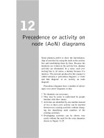
.27 Electrostatic paint transfer efficiency versus substrate conductivity for
plaques painted in a test laboratory.
Polar materials will have a faster inherent dissipation constant than nonpolar
materials because of their higher dielectric constant. Such charge dissipation
processes that occur with highly resistive substrates produce characteristically
low dissipation currents, in comparison to those of a conductive substrate.
Figure 27 plots the transfer efficiency versus part conductivity for plaques
of polymers having various conductivities. For these experiments, transfer effi-
ciencies were evaluated by paint thickness (theoretical yield is calculated based
on percent solids in the paint and time of plaque exposure to the paint, which
is sprayed at a particular delivery rate). A plateau of transfer efficiency versus
substrate conductivity occurs in the region of approximately 10
−5
S/cm, which
shows that paint transfer efficiency equivalent to that of metal can be observed
at levels of polymer conductivity significantly below metallic (35).
Practical aspects to grounding a conductively modified part in a painting
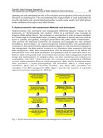
shop are of equal importance as the theory. Figure 28 illustrates that a charge
will typically travel a shorter distance if it moves toward the grounding clip
through the bulk of a semiconductor instead of along the surface. However, it
is not the physical distance, but instead the total resistance of the path that is
the determining feature for current distribution. The resistance of any given path
is the average resistivity of the material traversed multiplied by the distance
traveled. If substrate bulk conductivity is equal to or greater than that of the
40 Babinec and Cornell
F
IG
.28 Charge dissipation currents divide across all available paths using relative
power (IR drop) losses just as they would in a parallel electrical circuit.
F
IG
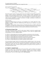
.29 Theoretical Percolation Curve. (From Ref. 39.)
Overview of the Automotive Plastics Market 41
conductive primer, discharge currents will travel through the bulk (the shorter
path to ground). Practical details such as the shape of the part, the placement of
grounding clips, and the number of grounding clips can clearly affect the rela-
tive merits of the various charge dissipation routes, and thus the optimal conduc-
tivity value. The published literature consensus of a target conductivity for elec-
trostatic painting appears to be a value of about 10
−5
to 10
−6
S/cm (35).
4.2 Preparation of Conductively Modified Plastics
Typical fillers employed in the preparation of conductive polymers are conduc-
tive carbon powders, fibers, and nanofibers. The literature offers general guide-
lines and many experimental examples of composite preparation. An important
guiding principal for all systems is percolation theory, which is used to predict the
amount of filler required to make a single phase material conductive through filler
addition. This theory is based on the universal experimental finding that a critical
state exists at which the fillers in an insulating matrix suddenly connect with each
other to create a continuous conductive network, as shown in Figure 29.
The percolation threshold, ϕ
c
, is the filler loading level at which the poly-
mer first becomes conductive, which is generally considered to be a value of
about 10
−8
S/cm. Comprehensive experimental and theoretical treatments de-
scribe and predict the shape of the percolation curve and the basic behaviors of
composites as a function of both conductive filler and the host polymer charac-
teristics (36–38). A very important concept is that the porous nature of the
conductive carbon powders significantly affect its volume filling behavior. The
typical inclusive structural measurement for conductive carbon powder porosity
is dibutyl phthalate absorption (DBP) according to ASTM 2314. The higher the
DBP, the greater the volume of internal pores, which vary in size and shape.
The crystallinity of the polymer also reduces the percolation threshold, because
conductive carbons do not reside in the crystallites but instead concentrate in
the amorphous phase. Eq. (2) describes the percolation curve (39).
ϕ
c
= (1 −ζ)
ͩ
1
1 + 4ρν
ͪ
Eq. (2)
where:
ϕ
c
= volume at percolation onset
ρ=density of carbon (taken as 1.82)
ν=DBP absorption on crushed carbon in cm
3
/g
ζ=crystalline volume fraction of the polymer
Table 14 compares the theoretical and experimental results for percolation
of two conductive carbon powders in a PP of two different melt flows, 4 and
44 g/10 min, when prepared by two melt-processing techniques, compression
42 Babinec and Cornell
T
ABLE
14 Comparison of Theoretical and Experimental Electrical Percolation
Behavior for PP
Predicted Experimental Experimental
percolation percolation loading for
PP Melt flow Carbon threshold Sample threshold (σ
c
)10
−5
S/cm
(g/10 min) type (%) preparation (wt %) (wt %)
44 XC-72
a
3.0 IM
c
10.0 11.0
XC-72 3.0 CM
d
3.0 5.0
44 EC-600
b
1.1 IM 3.0 3.0
EC-600 1.1 CM <1.0 <2.0
4 XC-72 2.4 IM 12.0 14.0
XC-72 2.4 CM 6.0 7.0
4 EC-600 0.9 IM 2.0 2.0
EC-600 0.9 CM 2.0 2.0
a
XC-72 obtained from the Cabot Corporation, DBP = 178;
b
EC-600 obtained from Akzo Nobel,
DBP = 495;
c
IM = Injection molded;
d
CM = Compression molded.
Source: Ref. 39.
and injection molding. The experimental thresholds did not match the theoretical
predictions when the sample was injection molded, under any conditions. How-
ever, the compression-molded samples showed generally better agreement be-
tween theory and experiment, especially when polymer viscosity was low. Fur-
ther, agreement with theory was found to be independent of the level of carbon
porosity, as evidenced by similar levels of agreement between carbons of two
distinctly different DBP values. The excellent predictive quality when the poly-
mer has low viscosity and the composite experiences ample time in the melt
state under zero shear (as with compression molding) suggests that flocculation
of the carbon and formation of a preferred carbon network structure are rate
limiting in morphology development (39).
In conductive polymer blends, for example, TPO, another phenomenon
must be taken into account—the localization of the conductive filler in only one
of the available phases. Such composites characteristically acquire conductivity
at lower filler loading levels than would be achieved by either of the two indi-
vidual polymer phases. This advantaged percolation using localization of filler
in a single phase of a polymer blend is called “double percolation.” Filler local-
ization has been reported in a large number of conductive blends (40–54).
The driving force for localization is believed to be the thermodynamics of
polymer/filler interaction, as described by Young’s equation. Sumita et al. have
calculated a carbon black wetting coefficient, ω
p
1
−p
2
, Eq. (3), from Young’s equa-
Overview of the Automotive Plastics Market 43
F
IG
.30 Transmission electron micrograph (TEM) of the morphology of a conduc-
tive TPO.
tion in order to predict the thermodynamically controlled location of the filler
in a binary blend (20,36).
ω
p
1
−p
2
=
γ
c−p
2
−γ
c−p
1
γ
p
1
−p
2
Eq. (3)
where:
γ
c−p
1
= interfacial tension between conductive carbon and polymer 1
γ
c−p
2
= interfacial tension between conductive carbon and polymer 2
γ
p
1
−p
2
= interfacial tension between polymer 1 and polymer 2
θ=contact angle of the polymer on the carbon
Prediction:
ω
p
1
−p
2
> 1 = carbon in the P
1
phase
ω
p
1
−p
2
<−1 = carbon in the P
2
phase
−1 <ω
p
1
−p
2
<+1 = carbon at the P
1
/P
2
interface
In blends of polar and nonpolar polymers, the carbon typically resides
in the more polar phase. For blends of low-surface-energy polymers, such as
polyolefins, there are conflicting accounts of positioning of the carbon
(21,39,55,56). It has been reported that conductive fillers are least likely to
reside in a PP phase, which is related to its exceptionally low surface energy.
44 Babinec and Cornell
When the conductive filler localizes in a minor phase of a blend, that
phase must be at least partially continuous for the composite to be globally
conductive. Morphology is often adjusted to keep a conductive minor phase
volume to a minimum, while maximizing continuity in an attempt to minimize
the additional cost incurred for the conductive filler. For example, in a rubber-
modified polypropylene, the carbon resides in the minor rubber phase. Figure
30 shows that the minor phase rheology of a conductive TPO. For this, the
conductive carbon resides fully in the elastomer phase, which is the dark region.
The minor elastomer phase morphology has been adjusted to be somewhat la-
mellar so that the conductive domains can be continuous within the composite
at low-volume fractions.
REFERENCES
1. Chem Eng News 58(40):29, 1980.
2. BRGTownsend Inc., P.O. Box F, Suite 130, 500 International Drive North, Mount
Olive, NJ 07828.
3. Automotive Plastics Report—2000, Market Search Inc.
4. RW Carpenter. Electroplating: back to the basics. The Society of Plastics Engineers
Regional Educational Technical Conference. March 1992.
5. Standards and guidelines for electroplated plastics. American Society of Electro-
plated Plastics. Englewood Cliffs, NJ: Prentice-Hall, Inc, 1984.
6. B Factor, T Russell, M Toney. Physical Review Letters, 1991, p. 1181.
7. Merriam-Webster’s Collegiate Dictionary, Tenth Edition. Merriam-Webster, Inc.
2001, p. 14.
8. S Granick. MRS Bulletin 33–36, 1996.
9. D Brewis, D Briggs. Polymer 22:7–16, 1981.
10. RA Ryntz. The Influence of Surface Morphology on the Adhesion of Coatings to
Thermoplastic Polyolefins Under Stress. In: The Annual Meeting of the Adhesion
Society, 18th. 1995.
11. E Tomasetti, R Legras, B Henri-Mazeaud, B Nysten. Polymer 41:6597–6602, 2000.
12. D Bergbreiter, B Walchuk, B Holtzman, H Gray. Macromolecules 31:3417–3423,
1993.
13. P Schmitz, J Holubka. Journal of Adhesion 48:137–148, 1995.
14. S Rzad, DC, M Burrell, J Chera. In: SAE International Congress and Exposition.
Detroit SAE, 1990.
15. R Bongiovanni, BG, G Malucelli, A Priola, A Pollicino. J Materials Science 33:
1461–1464, 1998.
16. M Hailat, HX, K Frisch. J Elastomers and Plastics 32:195–210, 2000.
17. T Ouhadi, JH, U.S. Patent 5,843,577, 1998.
18. T Ouhadi, JH, PCT WO 95/26380, 1995.
19. B Miller. Plastics World 15, 1996.
20. J Helms. Electrostatic painting of conductively modified injection molded thermo-
plastics. In: Coating Applications of Specialty Substrates. Society of Manufacturing
Engineers, 1995.
Overview of the Automotive Plastics Market 45
21. J Helms. Conductive TPOs for improved painting efficiency of bumper fascia. In:
TPOs in Automotive Conference. 1996.
22. T Derengowski, EB, J Helms. In SAE. 1998.
23. D Edge, DG, C Doan, S Kozeny, P Kim. The benefits of conductive TPO for
improving the painting of automotive part. In: TPOs in Automotive. 1998.
24. J Pryweller. Plastics News. 4, 1997.
25. Plastics Engineer. 32, 1998.
26. VTA News. 2, 1993.
27. B Miller. Plastics World. 73–77, 1996.
28. JD Gaspari. Plastics Technology. 14–15, 1997.
29. B Miller. Plastics World. 15, 1996.
30. H Scobbo, DG, T Lemmen, V Umamaheswaran. In: SAE Conference. 1998.
31. D Garner, AE. J Coatings Technology 63(803):33–37, 1991.
32. D Garner, AE. J Coatings Technology 64(805):39–44, 1992.
33. C Speck, AE. Transactions on Industry Applications 27(2):311–315, 1991.
34. A Elmoursi. In: IEEE Industry Applications Society Annual Meeting. 1991.
35. K Sichel. Carbon Black-Polymer Composites—The Physics of Electrically Con-
ducting Composites. New York: Marcel Dekker, 1982.
36. N Probst. Carbon Black—Science and Technology, Second Edition—Conducting
Carbon Black. ch. 8, 1993.
37. A Medalia. Rubber Chem and Technology 59:432, 1985.
38. S Babinec, RM, R Lundgard, R Cieslinski. Advanced Materials 12(23):1823–1834,
2000.
39. K Miyasaka, KW, E Jojima, H Aida, M Sumita, K Ishikawa. J Materials Science
17:1610, 1982.
40. S Asai, KS, M Sumita, K Miyasaka. Polymer Journal 24(5):415, 1992.
41. M Sumita, KS, S Asai, K Miyasake, H Nakagawa. Polymer Bulletin 25:265, 1991.
42. G Geuskens, E DK, S Blacher, F Brouers. European Polymer Journal 27:1261,
1991.
43. F Gubbels, RJ, Ph Teyssie, E Vanlathem, R Deltour, A Calderone, V Parente, J
Bredas. Macromolecules 27:1972, 1994.
44. F Gubbels, SB, E Vanlathem, R Jerome, R Deltour, F Brouers, Ph Teyssie. Macro-
molecules 28:1559, 1995.
45. B Soares, FG, R Jerome, Ph Teyssie, E Vanlathem, R Deltour. Polymer Bulletin
35:223, 1995.
46. M Sumita, KS, S Asai, K Miyasaka. In: Sixth Annual Meeting—PPS. Nice, France,
1990.
47. F Gubbels, RJ, E Vanlathem, R Deltour, S Blacher, F Brouers. Chem Materials 10:
1227, 1998.
48. R Tchoudakov, OB, M Narkis. Polymer Networks Blends 6:1, 1996.
49. M Narkis, RT, O Breuer. In ANTEC 95 1995.
50. R Tchoudakov, OB, M Narkis, A Siegmann. Polymer Engineering and Science
36(10):1336, 1996.
51. C Zhang, HH, X Yi, S Asai, M Sumita. Compos Interfaces 6:227, 1999.
52. J Feng, CC. Polymer 41:4559, 2000.
53. A Ponomarenko, VS, N Enikolopyan. Advances in Polymer Science 126, 1996.
54. R Lundgard, SB, R Mussell, A Sen. U.S. Patent 5,844,037. 1998.
46 Babinec and Cornell
55. J Helms, EB, M Cheung. U.S. Patent 5,484,838. 1996.
56. No 38 was given in the original document.
57. RW Cahn. #8, 1993.
58. RA Ryntz. Adhesion to Plastics: Molding and Paintability. Polymer Surfaces and
Interfaces Series. MW Urban, ed. Global Press, 1998, ch. 5.
59. J Israelachvili. Intermolecular & Surface Forces. 2
nd
ed. New York: Academic
Press, 1997.
60. RA Ryntz. Adhesion to Plastics: Molding and Paintability. Polymer Surfaces and
Interfaces Series. MW Urban, ed. Global Press, 1998, ch. 4.
61. DW Van Krevelen, PJH. Properties of Polymers, Their Estimation and Correlation
with Chemical Structure. Amsterdam: Elsevier, 1976, p. 170.
62. J Bicerano. Prediction of Polymer Properties. 2
nd
ed. New York: Marcel Dekker,
1996, pp. 195–196.
63. Teltech Resources Network Corp. Adhesives Age 38–44, 1996.
64. BN McBane. Automotive Coatings Monograph, Federation of Cosieties for Coat-
ings Technology. Blue Bell, PA: SAE, 1987, p. 39.
65. IA Hamley. Introduction to Soft Matter, Polymers, Colloids, Amphiphiles, and Liq-
uid Crystals. New York: Wiley, 2000.
66. RJ Young, PA Lovell. Introduction to Polymers, 2nd ed. London: Chapman and
Hall, 1991, ch. 4.
67. MF Ashby. Materials Selection in Mechanical Design, 2nd ed. Oxford: Butter-
worth/Heinemann Publishing, 1999.
68. RN Howard, RJ Young. The Physics of Glassy Polymers, 2nd ed. London: Chap-
man and Hall, 1997.
2
Plastics Processing
Steven D. Stretch
Emhart Fastening Teknologies, Inc., Mt. Clemens, Michigan, U.S.A.
1 INTRODUCTION
There are many reasons why plastics are today’s materials of choice in a wide
variety of applications. Plastic materials exhibit a broad and useful range of
properties that can be fitted to any number of specific environments. Plastics
are light, tough, strong, and environmentally resistant. It is their flexibility in
processing, however, that has allowed plastics to enjoy the level of success they
have achieved over the past 50 years.
Processing flexibility plays an important role in the overall plastics sce-
nario in two ways. First, flexibility makes it possible for plastics to be used in
the design of complex shapes that often cannot be produced with metals or other
types of materials. Second, the precision and rapid cycling that can be realized
in everyday manufacturing produces a compelling economic scenario that is
difficult or impossible for other material-process combinations to match.
This chapter will provide a broad overview of the variety of plastics pro-
cesses that are used to produce component parts. To gain a perspective, the
relationship between raw materials and processes will be explored. Next, the
fundamental physical mechanics of conversion will be outlined to develop an
appreciation for how specific techniques are used to create processes that can
be applied to achieve specific goals.
With this foundation in place, the factors used to make the underlying
process selection decision will be discussed. Because the selection of process
has important implications to coating of raw molded components, a method of
incorporating coating considerations into the decision will be introduced.
47
48 Stretch
Finally, an organized summary of key plastics conversion processes will be
presented as an aid to making the best coating decisions for specific application
scenarios.
2 OVERVIEW OF PLASTICS CONVERSION PROCESSES
The sheer number and variety of processes used for converting plastic raw mate-
rials into components can be daunting. Thankfully, it is possible to make sense
of it all by understanding the nature of the raw materials that can be used and
by viewing processes in terms of the basic physical mechanics that are involved
for each. This approach will make it relatively easy to understand which materi-
als can be used with what processes and what a given process is able to accom-
plish.
2.1 Raw Material Considerations
Plastic materials are based on hydrocarbons, a class of organic compounds that
contain hydrogen and carbon. The primary source of hydrocarbons today is
crude oil, although it is possible to produce them from coal, shale, or other
forms of fossil fuel. It is also possible to produce hydrocarbons from other
organic matter, such as cereal grains.
Hydrocarbons are interesting compounds because some of them lend
themselves to reaction by polymerization. This type of reaction produces plastic
materials from simple molecular building blocks. The building blocks combine
into chains that result in polymer molecules that are very large (in atomic terms).
The term polymers is from the Latin poly (meaning many) and mers (meaning
units). So plastics are described as hydrocarbons that are composed of “many
units.”
2.1.1 Raw Material Form
The first source of processing variety comes into play when the question of
when and how this polymerization reaction takes place. Raw materials may be
liquid components or they may be solids in the form of powders, granules, or
pellets. The raw materials may be presented for processing in a prepolymerized
form (polyethylene or acrylonitrile/butadiene/styrene [ABS]), they may be in a
partially reacted form (urethanes = polyols + isocyanates), or they may be in
the state of their precursor raw materials (phenolics and alkyds).
The general path from hydrocarbons to molding materials is shown in
graphical form in Figure 1. There are several considerations that determine the
form that raw materials take.
Physical Form of the Polymer Building Blocks. The raw materials or
units used to produce plastics are normally compounds that are in the form of
Plastics Processing 49
F
IG
.1 Possible raw material path to produce a precursor to present for process-
ing into molded parts.
liquids or gases. Because gases are difficult to handle and control, the reactions
involving them are normally done in a separate and highly controlled process
on a large scale. The production of polyethylene from ethylene gas is a good
example of this.
Number and Type of Building Blocks Used in the Polymerization Process.
In some cases, the polymerization may involve the use of a single building
block that is caused to repeatedly link to itself and form long chains, as is the
case of ε-caprolactam to form nylon 6. This type of reaction is referred to as
addition polymerization. In other situations, two building blocks are combined
to form a polymer, such as the polymerization of hexamethylenediame (HMDA)
and adipic acid to form nylon 6/6. This type of reaction is called condensation
polymerization. When liquid raw material constituents are used, it may be possi-
ble to directly convert them to parts, but this may be prevented if other factors
are involved.
Environment in Which the Reaction Must Take Place. In some situa-
tions, raw materials may react and polymerize readily when simply mixed to-
gether, such as epoxies. In others, unusual conditions of heat and pressure may
be required to accomplish the polymerization. For example, high pressures and
temperatures are required to produce polycarbonate. If unusual conditions are
needed, then raw materials are converted in a separate, dedicated process that
produces polymers in a basic form.
Presence of Other Physical Agents to Achieve the Desired Results. Most
polymerization reactions require the presence of one or more catalysts. A cata-
lyst is a compound or agent that promotes a reaction but that is not consumed
by the reaction and is not normally an important constituent of the finished
polymer. Because catalysts are often expensive, it often makes sense to use
them within the confines of a specific manufacturing process so that they can
be controlled and used again.
50 Stretch
Once the base polymer is prepared, it may be ready for commercial use.
In many cases, however, further work is required to enhance the physical prop-
erties offered by the polymer and to make it more forgiving during processing.
Some commercial products are produced by blending polymers together and in
many situations the base polmer is compounded with inorganic additives.
Inorganic additives such as glass fibers, pigments, heat stabilizers, UV
stabilizers, and flame retardants are commonly incorporated into basic polymer
formulations to impart special behavior. In most cases, these additives are com-
pounded into the base polymer after the reaction and presented for processing
after a separate operation is performed.
2.1.2 Direct vs. Indirect Conversion
The starting point for any process is thus defined by the nature and form of the
raw materials available. The scope of the process can be described to explain
how the transition from raw materials to finished product is made. The term
direct conversion is applied to processes that start with raw materials and pro-
duce parts in one step. Extrusion and injection molding are examples of this
type of process.
Other processes require that intermediate steps be performed to the raw
materials on the path to finished parts. Examples of indirect conversion are
thermoforming, which first requires the production of plastic sheet and injection
blow molding, which requires the production of a preform before finished parts
can be produced. Intermediate steps may be accomplished in-line as a defined
portion of the process, or the raw materials may be the result of a separate
process that was performed at a different location. The mechanisms of how
these intermediates are produced will, of course, have an impact on process
flexibility and economics.
2.1.3 Thermoplastics vs. Thermosets
Polymer reactions have another attribute that can have a significant effect on
processing. Some polymers are delivered in a form in which the polymerization
reaction is essentially complete. They are described by the broad term thermo-
plastics. Thermoplastic materials are converted to parts through the application
of heat and force. They are normally delivered as solid materials (pellets, pow-
ders, or granules) and are melted by the process and cooled to solidification to
produce their finished part form. Polymer materials that can be handled in this
way are often referred to as being melt processable. One of the chief advantages
of thermoplastics is that they can be remelted and used more than once (within
limitations) by the processor.
Other materials are delivered in a form in which the polymerization reac-
tion has not taken place or is only partially completed. In the case of polyure-
thanes, the isocyanate component is essentially unreacted and the raw material
Plastics Processing 51
is in liquid form. Phenolics and alkyd resins are delivered in solid form, but
their level of crosslinking has only been partially completed. These materials
are melted and then the crosslinking or polymerization is completed once they
are in the shape of their finished parts. These type of materials are referred to
as thermosets, and they normally cannot be remelted and reused.
2.1.4 Heat Management
Heat is a necessary component of all plastics processing and its proper manage-
ment is essential to producing quality parts. The type of material used is the
most important factor in determining a heat-management scenario for a given
process.
Thermoplastic materials by definition are melt processable. This implies
that a sufficient amount of heat be added to the material to melt it in order
to begin processing. Maintaining the material at a specific temperature during
processing is important, because a material’s viscosity or resistance to flow will
vary with temperature. In some situations, it may be desirable to heat the mate-
rial to a point where the polymer is almost wafer-thin. In others, the process
may dictate that the material be kept at a temperature where it is melted but still
has a degree of integrity so that it can be stretched or shaped.
Thermoset materials have special characteristics that have to be dealt with
differently, because chemical reactions take place during processing. These reac-
tions have to be properly staged because, in most cases, processing causes irre-
versible changes to take place. If the raw material components are liquids, they
only have to be heated to a temperature that will promote a controlled and
predictable reaction. In the cases where thermoset raw materials are in solid
form, they must be heated to the point where they are malleable or can be
moved according to the requirements of the process.
While heat has been added at the beginning of the process, it must then
be removed once parts have been formed. The way heat is removed is critical
because it affects the overall cycle of the process and influences the appearance
and properties of finished parts. With thermoplastics, the amount of heat that must
be removed will be somewhat less than the total heat introduced at the beginning
of the process. The amount of heat removed with thermosets may have to be
considerably more, because chemical reactions can produce additional heat during
part formation that must be managed in the finished components.
3 BASIC PROCESSING MECHANICS
The path from raw material to molded component may be either straightforward
or convoluted, but all plastics processing methods make use of fundamental
physical forces to accomplish work. Every plastics process uses one of six basic
physical strategies to produce parts.
52 Stretch
As is indicated in Figure 2, all of the major plastics processes can be
approached by understanding their basic strategies. By studying the strategy for
a process, it is possible to gain an understanding of its origins, possibilities, and
limitations.
3.1 Push Processes
Some processes produce parts by physically pushing liquid raw materials into a
closed mold. Processes that use this strategy can be generally classified as injec-
tion-type processes, and they all involve pushing (inducing shear flow upon) the
F
IG
.2 Classification of plastics processes in terms of basic mechanical strategies.
Plastics Processing 53
material. The raw materials may be unreacted or partially polymerized constit-
uents that are liquids at room temperature, as is the case for Reaction Injection
Molding (RIM) or for Liquid Injection Molding (LIM). These processes gener-
ally work with thermosets and reactions occur inside the mold itself. The key
to dealing with this type of process is to achieve very fast or turbulent flow so
that the constituents will be intimately mingled to maximize the reaction rate
and time to completion.
Working with thermosetting liquid materials has several advantages. Very
large parts can be produced with these processes, and significant structure can
be realized when glass fibers, mats, or other reinforcements are incorporated
into the process. Moderate levels of part detail are routinely achieved, but the
property combinations are dictated by the limited number of polymer types that
lend themselves to processing in this way.
Other processes deal with thermoplastics that are melted to a liquid state
and then pushed through channels into a closed mold. Thermoplastic injection
molding and all of its derivative processes use this approach to produce parts.
Melted thermoplastics are normally thicker or have a higher viscosity or resis-
tance to flow than the liquid components found in the RIM or LIM processes
and require higher pressures to process. Therefore, it is difficult if not impossi-
ble to push the materials fast enough to achieve turbulent flow conditions.
Melted thermoplastics have special characteristics, particularly because
pushing force creates what is generally described as Poiseuille Flow in the mate-
rial. When pushed, the molding material exhibits different levels of shear stress
across the thickness of the part. Variations in stress levels can be controlled
through design and processing, but are always a consideration in thermoplastic
injection processes. Stress variations can affect the physical strength of the part,
influence its ability to maintain shape and dictate its reaction when contacted
by solvents or other chemicals.
Push processes using thermoplastics are broadly applied and highly versa-
tile. It is possible to quickly produce highly complex shapes from very small to
moderate size that have a high level of detail. At the same time, tooling for
thermoplastic injection molding processes can be expensive because of the high
level of operating pressure usually encountered.
3.2 Squeeze Processes
This type of process uses the force of compression between two mold halves to
squeeze the material into the desired shape to produce finished parts. Two basic
methods are used to introduce material into the mold: charges and preforms.
The first and most common approach is to open the mold and introduce a
preweighed charge of solid material into the lower half of the mold. The mold
is then closed and the material is squeezed into the shape of the finished part.
54 Stretch
This is the method that is used to produce parts using the Sheet Molding Com-
pound (SMC) process. The charged raw material is a precompounded wet solid
mixture of thermosetting polyester resins and additives. Charged compression
molding normally uses thermosets as raw materials, although thermoplastic
compounds are beginning to gain acceptance for use in this process as well.
The second method of taking advantage of the compression approach is
to load the mold with a preformed shape. The advantage of the preform is that
more complex shapes can be produced and additional material can be introduced
through injection or other means to encapsulate the preform and provide a
unique finished product.
Compression processes can produce large parts, although the level of de-
tail is necessarily limited because the force used can only cause limited move-
ment of raw material. Because thermosets are commonly used, there is a limited
range of property profiles that can be realized by these processes.
3.3 Pull-Push Processes
The most prevalent form of plastics processing (by volume of material con-
verted) uses a pull-push strategy to move raw materials and convert them into
finished shapes. The extrusion processes pull material through a heating mecha-
nism and then push it through a die to produce two-dimensional profiles or
sheets of material.
Extrusion processes are significant producers of primary products and also
produce intermediates that can be subjected to further processing. The nature of
the process dictates that thermoplastic raw materials or rubbers be used. Melted
thermoplastics are viscous enough to be pushed through a die and still maintain
their shape until they are cooled and completely solidified.
There are several advantages to extrusion that explain its popularity. While
primarily restricted to thermoplastics and rubbers, a wide variety of polymers can
be formulated to have the strength required to hold their shape after being pushed
through a die. Tooling is cheap and application potential is plentiful.
There are still significant limitations to pull-push processing. Shapes pro-
duced by this strategy are necessarily limited to two-dimensional profiles, but
many practical applications exist in this realm. The key advantage is that very
long shapes can be extruded and cut to length to fit a variety of needs. Flat
profiles are useful for siding and window treatments, while hollow profiles are
extensively used for piping and ductwork. Meanwhile, complex profiles have
found application in window components and seals, moldings, and seals of vari-
ous types.
Extruded sheets are useful in their own right for glazing and architectural
panels, but they also form the basic raw materials for an entire realm of second-
ary processes.
Plastics Processing 55
3.4 Forming Processes
Thermoforming is used to describe a family of processes that use sheet stock in
the form of blanks as a starting point for producing shapes. In general, forming
methods are described as indirect conversion, open-mold processes. They are
extremely useful in producing large, simple shapes on inexpensive tools, partic-
ularly when overall volume requirements are low.
Sheet stock can be produced using variations of the physical mechanics
used by other processes. Simple drape forming uses the force of gravity-induced
creep to allow a preheated blank to form over an open male mold. Vacuum may
be applied to either a male or female mold to improve the formability and
improve detail. In an approach similar to other compressive processes, pressure
forming squeezes heated material between two mold halves to produce a crisply
finished shape. Finally, two sheets may be heated and formed outward against
the walls of a closed mold to produce hollow shapes.
3.5 Blowing Processes
This type of process uses compressed air to displace and form melted material
into shapes. The concept is generally described as blow molding. The applica-
tion of the strategy works well in the production of hollow shapes, and works
in much the same way as blowing up a balloon. Air pressure can be applied
over a wide surface area and can be useful in making very large parts.
The use of air pressure to move material has certain advantages, but it is
also subject to some specific limitations. Materials must be molten but still
viscous and strong enough to respond to the air pressure in a controlled way. If
the material is too thin, it will be unstable and difficult to control.
This restriction implies that only thermoplastic materials have the required
physical characteristics to qualify for this type of processing. Resin manufactur-
ers have developed special formulations that exhibit good melt strength and that
are predictable in the melted state. Thermosets that are based on unreacted liq-
uids or solids that do not have well-defined behavior during reactions do not
have the stability required for blow molding.
Because the force of compressed air is relatively low when compared to
the forces required to compress plastics or to push them into a closed mold, the
amount of detail and definition that can be achieved is somewhat limited. At
the same time, the application of air to produce a hollow shape also limits the
possibilities with regard the overall complexity of shapes that can be produced.
3.6 Rotating Processes
The use of centrifugal force can also be used to effectively produce hollow
shapes. Material, usually in fine granular or powdered form, is introduced into
56 Stretch
a heated, hollow mold while it is rotating. The material is deposited on the walls
of the mold and is built up to its ultimate wall thickness. This processing strat-
egy is generally referred to as rotational molding.
As with blow molding, the process is capable of producing very large
three-dimensional shapes such as those found in recreational equipment and
agricultural tanks. Because rotational molding operates with open molds at es-
sentially ambient pressure, tooling is economical and can be fabricated from
sheet metal.
Still, there are limits to this strategy. There are a limited number of poly-
mers that can be specially formulated so that they build up on the mold walls
in the appropriate way. Cycle times are relatively long when compared to other
processes. The level of detail and complexity that can be designed into rotation-
ally molded parts is somewhat limited, although special techniques have been
developed that are substantially expanding the horizons of this type of pro-
cessing.
4 SELECTING A PROCESS
The decision to produce a part from a particular process is the result of several
factors. First, the way a component is designed within the context of the overall
product or subassembly sets the stage for its possibilities and limitations. Next,
the chosen process must be capable of producing the part to the desired geome-
try and meet its defined performance requirements. Finally, the manufacturing
economics for the scenario must be favorable (1).
4.1 Components in Context
The key to success with plastics applications has its foundations in product
design. Once a product’s form has been visualized, it must be reviewed and
interpreted in terms of its component parts. Good, manufacturable component
designs are those that are based on an understanding of the capabilities of both
materials and conversion processes. Successful applications usually take advan-
tage of some of the general benefits of using plastic materials:
• The ability to consolidate parts
• The ability to integrate, reduce, or eliminate fasteners
• The ability to simplify or eliminate secondary operations
Workable solutions tend to be recognized and proliferated, because they
lead to better product performance and economics. While many designs can be
developed through imitation, unique and better solutions are normally the result
of an in-depth understanding of the possibilities.
Plastics Processing 57
Because every potential plastics application is described by a unique set
of circumstances, the degree of difficulty associated with process selection for
a given component can range from intuitively obvious to very complex. Situa-
tions that involve radical product redesign, short product life cycles, a limited
tooling budget, or uncertain volume forecasts tend to make process selection
more difficult, because historical precedent may have little or no relevance to
the decision at hand.
The most effective way to make component process-selection decisions is
to work within a framework that includes three basic elements: (1) a well-
defined statement of the problem; (2) a good understanding of the candidate
processes; and (3) a logical set of priorities for decision making.
The way to take advantage of an in-depth knowledge of processes is to
review complete products or subassemblies and consider how individual parts
should be defined within them. In other words, process selection should ideally
be integrated into a product’s concept development phase so that maximum
manufacturing flexibility is preserved from the outset. Components can thus be
defined within the product-as-a-system framework to uncover unique benefits
that may be associated with a particular process (2).
4.2 Process Capabilities
At the individual component level, each basic process type has a range of spe-
cific strengths and limitations that are derived from its fundamental strategy.
Each process type offers a unique profile of possibilities that makes it well
suited for particular types of applications. There are, however, some areas of
overlap, and many situations exist where more than one process can do a given
job.
A review of the fundamental process possibilities will help explain why
certain parts are produced using one strategy and not another. When application
requirements can be met by one or more competing processes, it is usually
simple economics that dictate the winner.
The capabilities of processes can be generally described by reviewing four
basic characteristics:
1. Part size. There are normally size limitations that are dictated by the
materials and the fundamental mechanics of a processing strategy.
When a process is used to produce parts outside of its acceptable part
size range, the quality of the parts or the economics will suffer.
2. Part shape. Tooling considerations and the approach to moving mate-
rial will determine what kind of shapes can be produced. Shapes can
be defined by their dimensionality. Pull/push processes, for example,
can usually only produce two-dimensional shapes with a constant
cross section because material is pushed through a die. Push processes
58 Stretch
use closed molds and can produce complex shapes that approach three
dimensions if slides or other types of mold action are employed. Pro-
cesses that use compressed air or centrifugal force can produce hollow
shapes that are truly three dimensional.
3. Part complexity. Again, the processing strategy places limitations on
just how much complexity can be produced in parts. The shapes pro-
duced using forming, compressed air or centrifugal force are limited
in their ability to reproduce surface detail and to incorporate fine fea-
tures such as standing ribs or bosses. Higher pressures used by com-
pression and push processes make it possible to produce parts with
higher levels of detail.
4. Material flexibility. Part of the utility of a processing strategy involves
the range of raw materials that can be successfully and economically
used. For example, the success of push-type processes is due at least
in some measure to the broad array of materials that can take advan-
tage of this strategy.
One good way to create a summary of the capabilities of different process
types is to use radar plots. Figure 3 shows each of the six process types and
allows for ready comparison.
Push processes lend themselves to the production of parts that are small-
to-moderately sized and that have a high degree of detail and complexity. They
are also prime contenders in situations where exacting performance require-
ments can be obtained by using different raw materials. Squeeze processes can-
not easily produce a high level of complexity or detail, but they can be used to
produce large parts that are very strong and that have excellent surface appear-
ance.
Pull/push processes are best employed in the production of profiles or
sheet stock. They take advantage of situations that involve the production of
parts that are cut-to-length and that can be produced continuously. Forming
processes, which use sheet as a raw material, are useful in producing simple
shapes under low pressure. Either very large parts or a large number of smaller
parts can be produced using a forming strategy.
Processes that use compressed air can be applied to producing large, hol-
low complex shapes with a moderate level of detail. Similar hollow shapes can
be produced using centrifugal force, although larger parts are possible by this
approach. Material availability is limited, as is the amount of complexity that
can be incorporated.
4.3 Part Economics
When more than one process can produce a part, the ultimate choice is normally
driven by finished part economics. Ultimately, part costs are viewed as the cal-
Plastics Processing 59
F
IG
.3 A comparison of process capabilities. Comparison of basic process capabilities using radar plots. Variables
are rated from 1 to 10. Higher numbers and greater surface area are indications of higher inherent process capa-
bility.
60 Stretch
culated variable cost per unit. Variable costs, however, do not always reflect the
total situation because capital investments in tooling must also be made to put
the part into production.
There is normally an inverse relationship between part cost and tooling
cost. Logically, a larger investment in tooling will generate benefits such as
faster cycles or production rates, higher production capacity, or the ability to
produce more complex parts. These factors will tend to drive individual part
costs down.
Uncertainty can color the process-selection decision, particularly because
capital investment in tooling can represent substantial financial risk. For exam-
ple, the decision may be made to produce soft tools for pressure forming for a
new product where there is some question about volume projections. Hard tool-
ing for injection molding would result in lower part costs, but the up-front in-
vestment in soft tooling is much smaller and defrays product risk until the uncer-
tainty is removed.
4.3.1 Capital Costs
Each process has its unique requirements for tooling, but the costs are generally
related to the following factors: (1) part size or total projected area; (2) mold
structural requirements; (3) materials of construction; (4) cooling management
needs; and (5) complexity of the part’s geometry.
Part size or projected area (in closed molds) dictates the overall size
of the mold. Multiple cavity molds for small parts may require as much pro-
jected area as the single cavity footprint for a large part. The overall size influ-
ences the structural requirements for the mold, although the general structural
needs are also determined by the operating pressures generated during pro-
cessing.
Materials of mold construction are chosen based on their structural
strength and durability. If only a few parts are required, as is normally the case
for prototype molds, it is usually possible to use cheaper materials of construc-
tion for the mold.
These factors in combination with the overall structural requirements dic-
tate common choices of mold materials for different processes. For example,
high-grade tool steel is normally required for injection molding because of high
pressures, while rotational molding tools can normally be built by fabricating
metal plate. The requirements for low pressure forming molds can even be sim-
pler—wood or nickel-coated epoxy will often suffice.
Some processes require cooling water for production molds, and the need
for cooling lines or flooding jackets can increase the tooling cost. The combina-
tion of cooling lines and cavity replication represent the majority of the labor
required to produce a mold. Large or complex parts require a substantial effort
in machining for basic cavity replication. The presence of fine details normally
Plastics Processing 61
implies the use of electrodischarge machining (EDM) to produce with accuracy.
More complexity translates into higher cost.
4.3.2 Variable Costs
Variable or per-unit part-cost determinations require careful analysis and are
influenced by several factors:
Raw Material Cost. The choice of material has a significant impact on
the overall part cost. The cost of plastic resins varies widely and prices are
related to physical property performance. Under normal circumstances, parts
should be produced from the material that best meets application requirements
at the lowest cost.
Finding the most cost-effective material is not always a simple task. The
properties of different materials often overlap, creating many situations in which
more than one material will perform well in the part. In some situations, using
less of a higher cost material may be more cost-effective than using more of a
lower performing one. At the same time, one of two similar materials may be
easier to process than the other.
Because plastics are sold by weight, it is important to view part economics
in terms of volume. A kilogram or pound of a material with a low density or
specific gravity will produce more parts than an equal weight of a heavier one.
Processing Costs. Each process has an inherent variable cost structure.
Considerations in this area include machine costs, energy costs, labor costs, and
the costs associated with auxiliary equipment that may be needed to successfully
perform processing. There may be appreciable setup charges in some situations. In
general, larger parts require larger equipment that costs more on a per hour basis.
Cycle Time. How quickly parts can be produced is an important consid-
eration. The speed at which thermoplastics can be safely molded is related to
the thickness of the part, which determines how rapidly the part will cool and
be safe to handle without deformation. Thermoset cycles are also determined
by the rate of reaction and how quickly parts can develop the required green
strength.
One useful technique for decreasing the effective cycle time for most pro-
cesses is to build molds that are capable of producing multiple parts per cycle.
For example, a part running on a 60-second cycle in a single cavity mold will
produce 60 parts per hour. If a 16-cavity mold is deployed, on the order of 960
parts can be produced in an hour. Multiple cavities will raise tooling costs, but
may have the effect of dramatically lowering the processing costs associated
with each part.
Secondary Operations Costs. In some cases, raw molded parts may re-
quire labor to prepare them for coating or for ultimate sale. The need may be
62 Stretch
simple, such as manually degating parts as they come out of the mold. On the
other hand, raw parts may require substantial hand or machine trimming, sand-
ing, or surface repair to allow them to be coated or to elevate them to a saleable
condition.
5 COATING CONSIDERATIONS
Because the coating of raw molded parts can represent a substantial cost, the
process-selection decision must incorporate the impact of this operation into the
overall scenario. In some cases, it may be possible to produce precolored or
color-matched parts and avoid the need for secondary operations altogether. In
other situations, coatings may be necessary so that the part will meet its defined
requirements.
The chosen material and process combination will have a significant im-
pact on the coating process that is applied to the raw molded part. The material
will influence the type of coating used, while the process will dictate what kind
and how much surface preparation is required to achieve the desired results.
5.1 Materials
The material used to produce the part dictates the nature of the substrate that
must be coated. Material selection is often entwined in the process-selection
decision because not all materials can be used with every process. The ultimate
decision may be material-driven, process-driven, or it may represent a compro-
mise based on a variety of factors. In any case, the resulting material substrate
and its own particular characteristics must be dealt with in terms of coatings
performance.
Important decisions must be made based on the substrate material, such as
finding the coating material and method that best addresses factors like surface
adhesion, appearance, durability, surface properties, and solvent migration. A
detailed description of this selection process is covered elsewhere in this text.
5.2 Surface Appearance
The selected process will produce a raw molded part that may or may not re-
quire surface preparation prior to coating. The surface finish may be limited by
the inherent capabilities of the process. In general, higher pressure processes
can produce better surface definition than processes that operate at low pres-
sures. Push and squeeze type processes can often produce excellent surface defi-
nition and are capable of generating Class A surfaces or detailed grains out of
the mold.
Blow and rotating type processes operate at lower pressures, but can still
achieve a good degree of surface definition. These processes can generate many
Plastics Processing 63
standard surface grains and hold them well in moderately complex shapes. Matte
or low-gloss surfaces can also be reproduced and held reasonably well.
Pull/push and forming type processes are generally more limited. Extruded
profiles cannot be expected to produce a Class A surface or to hold a grain.
Extruded sheet can be produced with a smooth surface or can be embossed to
achieve a good grain. If the sheet is to be formed, then the problem becomes
more difficult. The challenge with forming is to hold the surface or grain consis-
tently as the sheet is stretched. Here, part geometry and materials play an impor-
tant role in defining what is possible in a specific situation.
Some material and process combinations are inherently limited in their
ability to reproduce surfaces with fidelity. If the surface is less than perfect,
then manual intervention is indicated. Blemishes may have to be filled and the
entire surface may have to be sanded in order to achieve a level of appearance
needed.
5.3 Stress Levels
By definition, the act of plastics processing implies that stresses will be gener-
ated in the material. While the subject of stress in plastic parts is complex and
beyond the scope of this chapter, some generally useful statements can be made.
The act of producing a compatible interface between coating and substrate
can disrupt the stress patterns that are present on the surface of the part and
result in a lowering of the part’s physical properties. Stress disruption or relief
can also induce stress cracking in the part surface. The degree to which this
becomes important depends in part upon the levels of molded-in stress that are
generated during processing. These levels are dependent to a degree upon the
inherent nature of the selected process but can be influenced by the specific
processing conditions that are used to produce the part.
Further performance degradation can result from solvent migration into
the wall of the part over time. The effects of solvents may not be immediately
evident and can cause long-term failure of the part weeks or months after it is
has been put in service. Careful selection of solvents and cosolvents used with
the coating can prevent unnecessary and costly field failures.
6 PROCESS PROFILES
This portion of the chapter will provide a summary of plastics processes that
will act as a reference.
6.1 Push Processes
Processes that push material into a closed mold are widely employed. In total,
push processes offer the most overall versatility for general part manufacturing.