Extractive Metallurgy of Copper Part 8 doc
Bạn đang xem bản rút gọn của tài liệu. Xem và tải ngay bản đầy đủ của tài liệu tại đây (630.05 KB, 30 trang )
CHAPTER
12
Direct-To-Copper Flash Smelting
Previous chapters show that coppermaking from sulfide concentrates entails
two
major steps: smelting and converting. They also show that smelting and
converting are part
of
the same chemical process, Le.:
oxidation
of
Fe and
S
from
a Cu-Fe-S phase.
It has long been the goal
of
metallurgical and chemical engineers to combine
these
two
steps into one continuous direct-to-copper smelting process.
The principal advantages of this combining would be:
(a) isolation
of
SOz
emission to a single, continuous gas stream
(b)
minimization
of
energy consumption
(c) minimization
of
capital and operating costs.
This chapter
(i)
describes direct-to-copper smelting in
2002
and (ii) examines the
degree to which its potential advantages have been realized. The chapter
indicates that the principal problems with the process are that:
(a) about
25%
of
the
Cu
entering a direct-to-copper smelting furnace ends up
dissolved in its slag
(b) the cost
of
recovcring this
Cu
will probably restrict future expansion
of
direct-to-copper smelting to low-Fe concentrates (e.g. chalcocite
(Cu2S)
and bornite (Cu5FeS4) concentrates) rather than high-Fe chalcopyrite
concentrates.
12.1
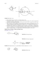
The Ideal Direct-to-Copper Process
Fig.
12.1
is
a sketch
of
the ideal direct-to-copper process. The principal inputs to
the process are:
187
188
Extractive
Metallurgy
of
Copper
concentrate, oxygen, air, flux and recycles.
The principal outputs are:
molten copper, low-Cu slag, high-SO2 offgas.
The process is autothennal. With highly oxygen-enriched blast, there
is
enough
excess reaction heat to melt all the Cu-bearing recycle materials from the smelter
and adjacent refinery, including scrap anodes. The process is continuous.
The remainder of this chapter indicates how close we have come to this ideality.
Concentrates
Flux
and reverts
Scrap copper
Oxygen and air
SO2
-
rich offgas
Liquid
copper
ready for refining
Slag
low
enough
in
Cu
for direct discard
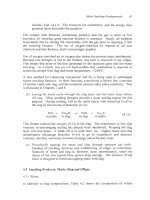
Fig.
12.1.
Ideal single-furnace coppermaking process. Ideally the copper
is
low
in
impurities, the slag is discardable without Cu-recovery treatment and
the
offgas is strong
enough in
SO1
for
sulfuric acid manufacture.
12.2
Industrial Single Furnace Direct-to-Copper Smelting
In
2002, single furnace direct-to-copper smelting is done
by
only one process
-
Outokumpu flash smelting, Fig.
1.4.
It is done in
two
locations; Glogow, Poland
(Czernecki
et
al.,
1998, 1999a,b,c) and Olympic Dam Australia (Hunt
et
al.,
1999a,b). Both furnaces treat chalcocite-bornite concentrates.
For several years the Noranda submerged-tuyere process (Fig.
1.5)
also
produced copper directly (Mills
et
al.,
1976). It now produces high-grade matte,
72-75% Cu. The change was made to increase smelting rate and improve
impurity elimination.
The products of direct-to-copper flash smelting (Table 12.1) are:
Direct-To-Copper
Flash
Smelting
189
copper
offgas
99%
Cu,
0.04
to
0.9%
S,
0.01%
Fe,
0.4%
0,
1280°C
15
to 20 volume%
SO2,
1350°C.
slag
14
to
24%
CU,
-1300°C
As with conventional matte flash smelting, the temperature of the furnace is
controlled by adjusting;
(a) the degree of oxygen enrichment of the blast,
i.e.
the amount of
N2
'coolant' entering the furnace
(b) the rate at which fossil fuel is burnt in the furnace.
The
O2
content of industrial direct-to-copper flash furnace blast is
50
to
90
volume%
02,
depending on the furnace's solid feed mixture. Considerable
fossil
fuel is burnt in the reaction shaft and in settler burners, Table
12.1.
12.3
Chemistry
Direct-to-copper smelting takes place by the schematic (unbalanced) reaction:
Cu2S,CugFeS4
+
O2
+
Si02
+
Cu;
+
Fe0,Fe3O4,SiO2
+
SO2
concentrate in oxygen flux molten slag in offgas
enriched
blast
(12.1).
Just enough
O2
is supplied to produce metallic copper rather than
Cu2S
or
Cu20.
In practice, the flash furnace reaction shaft product is a mixture of overoxidized
(oxide) and underoxidized (sulfide) materials. Individual particles may be
overoxidized
on
the outside and underoxidized on the inside. The overoxidized
and underoxidized portions react like:
2C~20
+
CU~S
-+
~CU;
+
SO,
(1
2.2)
2Fe304
+
Cu2S
+
2Cui
+
6Fe0
+
SO2
to produce molten copper, molten slag and SO2.
Industrially, the overall extent of Reaction 12.1 is controlled by:
(12.3).
(a) monitoring the Cu content of the product slag and the
S
content of the
product copper
(b) adjusting the:
190
Extractive Metallurgy ofCopper
0,
-in
-
blast inwt rate
concentrate input rate
ratio based on these measured Cu-in-slag and S-in-copper values.
An increasing
%
Cu-in-slag
is
reversed by decreasing the Oz/concentrate ratio
and vice versa. The
%
Cu-in-slag is kept between
14
and 24%.
12.4
Industrial Details
Operating details of the two direct-to-copper flash furnaces are given in Table
12.1. The furnaces are similar to conventional flash furnaces. Differences are:
(a) the hearths are deeply 'bowl' shaped to prevent molten copper from
contacting the furnace sidewalls
(b) the hearths are more radically arched and compressed to prevent their
refractory from being floated by the dense
(7.8
tonnes/m3) molten copper
layer (Hunt, 1999)
(c) the furnace walls are extensively water cooled and the hearth extensively
air cooled to prevent metallic copper from seeping too far into the
refractories
(d) the refractories are monolithic to prevent molten copper from seeping
under the bricks, solidifying and lifting them.
Also,
the copper tapholes are designed to prevent the out-flowing molten copper
from enlarging the taphole to the point where molten copper contacts cooling
water.
Olympic Dam's molten copper passes through magnesite-chrome brick (inside),
a silicon carbide insert and
a
graphite insert (outside) (Hunt
et
al.,
1999b). The
graphite insert is replaced after -1200 tonnes of tapped copper and the silicon
carbide insert
is
replaced after -2400 tonnes. Excessive copper flow (i.e. an
excessive taphole diameter) initiates earlier replacement.
12.5
Control
The compositions
of
the industrial furnace products are controlled by adjusting
the ratios:
0,
-in -blast input rate
concentrate input rate
and
Direct-To-Copper Flash Smelting
191
Table
12.1.
Details of Olympic Dam and Glogow direct-to-copper Outokumpu flash
furnaces. Note the high product temperatures as compared to matte smelting, Table
5.1.
Smelter
WMC Resources Olympic KGHM Polska Miedz
Dam, Australia
Glogow
Poland
Startup date 1999
Size, inside brick,
rn
hearth: w
x
1
x
h
reaction shaft
diameter
height, above settler roof
diameter
height above settler
roof
gas uptake
slag layer thickness,
m
copper layer thickness,
m
active slag tapholes
active copper tapholes
concentrate burners
settler burners
Feed details, tonnedday
new concentrate (dry)
oxygen
silica flux
recycle flash furnace dust
other
Blast details
blast temperature, "C
volume%
O2
flowrate, thousand Nm3/hour
Production details
copper production, tonnesiday
composition
temperature, "C
slag production, tonnesiday
mass%
Cu
mass% Si02/mass%Fe
temperature,
"C
Cu-from-slag recovery method
offgas, thousand Nm'/hour
volume%
SO2,
leaving furnace
temperature,
"C
dust production, tonnedday
burnt in reaction shaft
Hydrocarbon fuel inputs, kg/hour
6.3
x
19.2
x
1.9
4.8
5.8
3.7
7.5
0-0.65
0.5-0.85
2
8
1
2
1200-1600: 41-56%
CU
90-450
12-120 (95%
Si02)
0-144
ambient
SO-90
22
390-680
99%
Cu,
0.7
to
0.85%
S,
0.4%
0
1280
24
0.5
1320
electric furnace
25
19
1320-1400
boiler
65,
ESP
55
oil,
0-200
620-883
1978
9.2
x
26.4
x
3.0
7.4
8.3
6.7
12.3
0.5
0.7
6
10
4
normally none
2000 (28%
Cu)
self- fluxing
270
IO0
desulfurizing dust
140
75
32
392
0.007%
Fe,
0.25%
Pb
1280
1050
14
5.7*
1290
electric furnace
35
15
I320
260
0.04%
S,
0.45?'00,
oil,
300
burnt in settler burners oil,
900-1200
0
'32%
SO2;
5.6%
Fe;
10%
A1203;
13.4%
CaO;
6.9%
MgO;
13.7%
Cu;
3%
Pb
192
Extractive
Metallurgy
of
Copper
flux input rate
concentrate input rate
The temperatures of the products are controlled by adjusting the oxygen-
enrichment level of the blast
(as
represented by the
N2/02
ratio) and the rate at
which fossil fuel is burnt in the furnace.
12.5.1
Target:
No
Matte Layer to Avoid Foaming
The Glogow and Olympic Dam furnaces are operated with 02/concentrate ratios
which are high enough to avoid forming a Cu2S layer. This is done to avoid the
possibility of foaming slag out the top of the furnace (Smieszek
et
al.,
1985;
Asteljoki and Muller, 1987; Day, 1989; Hunt
et al.,
1999a).
A
molten Cu2S layer, once built up between the molten copper and molten slag
layers, has the potential to react with slag
by
reactions like:
2C~20
+
CU~S
+
6Cu;
+
SO,
in slag matte
2cuo
+
cu2s
-+
4cu;
+
so,
in slag matte
(12.2)
(12.4)
2Fe304
+
Cu2S
-+
2Cui
+
6Fe0
+
SO2
inslag matte
(12.3)
all of which can produce
SO2
beneath the slag layer.
Foaming is particularly favored if the input 02/concentrate ratio
is
subsequently
increased to shrink
or
remove an existing Cu2S layer.
This results in a highly
oxidized slag, fill of Fe304, CuO and Cu20, which has great potential for
producing
SO2
beneath the slag layer.
The foaming problem is avoided by ensuring that the 02/concentrate ratio
is
always at
or
above its set point, never below. This may lead to high copper
oxide-in-slag levels but it avoids the potentially serious operational problems
caused by foaming (Hunt
et
al.,
1999a). S-in-copper below -1%
S
guarantee
that a Cu2S layer does not form (Fig. 9.2a)*.
*Glogow copper contains
0.04%
S,
Le.
much less than
is
necessary to prevent matte layer formation.
This extra oxidation is done to oxidize Pb (from concentrate) to PbO, keeping Pb-in-copper below
0.3%.
Direct-To-Copper Flash Smelting
I93
12.5.2
High
%Cu-in-slag from
no-matte-layer strategy
An unfortunate side effect
of
the above no-matte-layer strategy is high %Cu-in-
slag, mainly as dissolved Cu20. It arises because there is no permanent layer of
CuzS in the furnace
to
reduce Cu20 to metallic copper, Reaction
(1
2.2).
Simply stated, direct-to-copper smelting is operated in a slightly over-oxidizing
mode
to
prevent the foaming described in Section 12.5.1. The downside of
operating this way is
14
to 24% Cu in slag, Table 12.1.
12.6
Cu-in-Slag: Comparison with
Conventional Matte Smelting/Converting
A significant difference between direct-to-copper flash smelting and flash
smelting/Peirce-Smith converting is the large amount
of
Cu in direct-to-copper
slag. This extra Cu-in-slag arises because:
(a)
%
Cu in direct-to-copper slags (14-24%, Table 12.1) is much greater than
%
Cu in conventional smelting slags (1-2% Cu) and converting slags
(b) the amounts of slag produced
by
direct-to-copper smelting and
(-6%
CU)
conventional smelting/converting are about the same.
Also, direct-to-copper slags contain most of their Cu in oxidized form (Le.
copper oxide dissolved in the molten slag)
-
so
they must be reduced with
carbon to recover their Cu.
12.6.1
Electric furnace
Cu
recovery
Both direct-to-copper smelters reduce their flash furnace slag in an electric slag
cleaning furnace. The slag flows from the flash furnace directly into an electric
furnace where it is settled for about
10
hours under a 0.25 m blanket of
metallurgical coke (Czernecki
et
al.,
1999b). This coke reduces the oxidized Cu
from the slag by reactions like:
cu20
+
c
-+
2cu;
+
co
CUO
+
c
-+
cu;
+
co
Magnetite (molten and solid) is also rerluced:
Fe304
+
C
+
3Fe0
+
CO
(12.5)
(12.6).
(12.7)
and some FeO is inadvertently reduced
to
Fe by the reaction:
194
Extractive Metallurgy ofcopper
FeO
+
C
+
Fe
+
CO
(12.8).
The Fe joins the newly reduced copper.
Glogow
results
The Cu content of the Glogow direct-to-copper slag is lowered from -14% Cu to
-0.6% Cu in an 18
000
kVA electric furnace. The metallic product is (Czernecki
et
u1,
1999b):
70-80%
CU
-5%
Fe
15-25% Pb (from Pb in the concentrate).
This product is too impure to be sent directly to anode-making. It is oxidized in
a Hoboken converter (Section 9.6.1) to remove its Fe and Pb, then sent to anode-
making.
Olympic
Dam
results
Olympic Dam lowers its direct-to-copper slag from 24% to
-4%
in its 15
000
kVA electric furnace (Hunt
et
al.,
1999a).
It
could lower it more by using more
coke and a longer residence time, but the copper product would contain
excessive radioactive '"Pb and
'"Po,
from the original concentrate.
Instead, the Cu-in-slag is lowered further by
solidificationicommunitiodflotation
in its mine flotation circuit, Section 11.5.
12.7
Cu-in-Slag Limitation
of
Direct-to-Copper Smelting
The principal advantage of direct-to-copper smelting is isolation of
SO2
evolution to one furnace. The principal disadvantage
of
the process is its large
amount of Cu-in-slag.
Balancing these factors, it appears that direct-to-copper smelting is best suited to
Cu2S, Cu5FeS4 concentrates. These concentrates produce little slag
so
that Cu
recovery from slag is not too costly.
Direct-to-copper smelting will probably not, however, be suitable for most
chalcopyrite concentrates,
-30%
Cu. These concentrates produce about 2 tonnes
of slag per tonne of Cu
so
that the energy and cost of recovering
Cu
from their
slag is considerable. Only about
60%
of new Cu in concentrate would report
directly to copper,
40%
being recovered from slag.
Direct-To-Copper
Flash
Smelting
195
Davenport
et
ai.
(2001) confirm this view but Hanniala
et
al.
(1999) suggest that
direct-to-copper smelting may be economic even for chalcopyrite concentrates.
12.8
Direct-to-Copper Impurities
The compositions of the anode copper produced by the direct-to-copper smelters
are given in Table 12.2. The impurity levels of the copper are within the normal
range
of
electrorefining anodes, Chapter
15.
The impurity levels could be
reduced further by avoiding recycle of the flash hrnace dust.
Impurities do not seem therefore, to be a problem in the
two
existing direct-to-
copper smelters. However, metallic copper
is
always present in the direct-to-
copper furnace, ready to absorb impurities. For this reason, concentrates
destined for direct-to-copper smelting should always be carefully tested in a pilot
furnace before being accepted by the smelter.
Table
12.2.
Anode compositions from direct to copper
smelters.
Olympic Dam
Glogow
I1
ppm
in
copper
Impurity
pp
m
in
copper
Ag
200-300 1500-3500
AS
250-350 500-800
Au
10-20
Bi
100-150 10-30
Fe
20-200
200-400
Ni
20-40 500-
1000
Pb
10-50 2000-3000
S
20-30
Sb 5-15 50-200
Se
150-350
100
Te
30-50
12.9
Summary
Direct-to-copper smelting is smelting of concentrate directly to molten copper in
one furnace. In 1994, it is practiced in
two
smelters; Glogow
I1
(Poland) and
Olympic Dam (Australia). In both cases the smelting unit is an Outokumpu
flash furnace.
The main advantage of the process is its restriction
of
SOz
evolution to a single
continuous source of high S02-strength gas. In principal, the energy, operating
and capital costs of producing metallic copper are also minimized by the single-
furnace process.
196
Extractive Metallurgy
of
Copper
Metallic copper is obtained in a flash furnace by setting the ratio:
0,
-in -blast input rate
concentrate input rate
at the point where all the Fe and
S
in the input concentrate are oxidized. The
ratio must be controlled precisely, otherwise Cu2S or
Cu20
will also be
produced. Avoidance
of
forming a molten Cu2S layer in the furnace
is
particularly important. Reactions between Cu2S layers and oxidizing slag have
caused rapid
SOz
evolution and slag foaming.
Direct-to-copper flash smelting has proven effective
for
SO2
capture. However,
15-35%
of
the Cu-in-concentrate is oxidized, ending up as copper oxide
dissolved in slag. This copper oxide must be reduced back to metallic copper,
usually with coke.
The expense
of
this Cu-from-slag recovery treatment will probably restrict future
direct-to-copper smelting to concentrates which produce little slag. Chalcopyrite
concentrates will probably continue to be treated by multi-furnace processes
-
either by conventional smeltingkonverting
or
by continuous multi-furnace
processing, Chapter 13.
Suggested Reading
Czemecki, J., Smieszek,
Z.,
Miczkowski,
Z.,
Dobrzanski, J. and Warmuz, M. (1999)
Copper metallurgy at the KGHM Polska Miedz S.A.
-
present state and perspectives. In
Copper 99-Cobre 99 Proceedings
of
the Fourth International Conference,
Vol.
V
Smelting Operations and Advances,
ed. George, D.B., Chen, W.J., Mackey P.J. and
Weddick, A.J., TMS, Warrendale, PA, 189 203.
Davenport, W.G., Jones, D.M., King, M.J. and Partelpoeg, E.H. (2001)
Flash Smelting,
Analysis, Control and Optimization,
TMS, Warrendale,
PA
(especially Chapters 19-2
1).
Hunt, A.G.,
Day,
S.K.,
Shaw,
R.G.
and West,
R.C.
(1999)
Developments in direct-to-
copper smelting at Olympic Dam. In
Copper 99-Cobre 99 Proceedings ofthe Fourth
International Conference,
Vol.
V
Smelting Operations and Advances,
ed. George, D.B.,
Chen, W.J., Mackey, P.J. and Weddick, A.J.,
TMS,
Warrendale, PA, 239 253.
References
Asteljoki, J.A. and Muller,
H.B.
(1987) Direct smelting
of
blister copper
-
flash smelting
tests
of
Olympic Dam concentrate.
In
Pyrometallurgy
87,
The Institution
of
Mining and
Metallurgy, London, England,
265
283.
Direct-To-Copper Flush Smelting
197
Czernecki, J., Smieszek,
Z.,
Gizicki,
S.,
Dobrzanski, J. and Warmuz, M. (1998) Problems
with elimination
of
the main impurities in the KGHM Polska Miedz S.A. copper
concentrates from the copper production cycle (shaft furnace process, direct blister
smelting in a flash furnace). In
Sulfide Smelting ’98,
ed. Asteljoki, J.A. and Stephens,
R.L.,
TMS,
Warrendale, PA, 3 15-343.
(a) Czernecki, J., Smieszek,
Z.,
Miczkowski,
Z.,
Bas, W., Wamuz, M. and Szwancyber,
G. (1999) Changes in the construction of the KGHM flash smelting furnace of Glogow I1
introduced in the years 1996-1998. In
Proceedings of
gh
International Flush Smelting
Congress,
Australia, June 6-12, 1999.
(b) Czerneclu,
J.,
Smieszek,
Z.,
Miczkowski,
Z.,
Dobrzanski, J., Bas, W., Szwancyber,
G.,
Warmuz, M. and Barbacki, J. (1999) The process flash sla cleaning in electric
furnace at the
Glogow
I1 copper smelter. In
Proceedings of
9’
International Flash
Smelting Congress,
Australia, June
6-
12, 1999.
(c) Czernecki, J., Smieszek,
Z.,
Miczkowski,
Z.,
Dobrzanski, J. and Wamuz, M. (1999)
Copper metallurgy at the KGHM Polska Miedz S.A.
-
present state and perspectives. In
Copper 99-Cobre 99 Proceedings of the Fourth International Conference,
Vol.
V
Smelting Operations and Advances,
ed. George, D.B., Chen, W.J., Mackey P.J. and
Weddick, A.J., TMS, Warrendale, PA, 189 203
Davenport, W.G., Jones, D.M., King, M.J. and Partelpoeg,
E.H.
(2001)
Flash Smelting,
Analysis, Control and Optimization,
TMS,
Warrendale, PA (Chapter 19).
Day, B.E. (1989) Commissioning
of
the Olympic Dam smelter. Paper presented at the
Non-Ferrous Smelting Symposium of the Australasian Institute of Mining and Metallurgy
(Parkville, Victoria), held at Port Pirie, South Australia, September 1989, 57
60.
Hanniala,
P.,
Helle,
L.
and Kojo, I.V. (1999) Competitiveness of the Outokumpu flash
smelting technology now and in the Third Millennium. In
Copper 99-Cobre 99
Proceedings of the Fourth International Conference,
Vol.
V
Smelting Operations and
Advances,
ed. George, D.B., Chen, W.J., Mackey P.J. and Weddick, A.J., TMS,
Warrendale, PA, 221 238.
(a) Hunt, A.G., Day,
S.K.,
Shaw, R.G., Montgomerie, D. and West,
R.C.
(1999) Start
up
and operation of the #2 direct-to-copper flash furnace at Olympic Dam. In
Proceedings of
9Ih
International Flush Smelting Congress,
Australia, June 6-12, 1999.
(b) Hunt, A.G., Day,
S.K.,
Shaw, R.G. and West, R.C. (1999) Developments in direct-to-
copper smelting at Olympic Dam. In
Copper 99-Cobre 99 Proceedings of the Fourth
International Conference, Vol.
V
Smelting Operations and Advances,
ed. George, D.B.,
Chen, W.J., Mackey, P.J. and Weddick, A.J.,
TMS,
Warrendale, PA, 239 253.
Mills,
L.A.,
Hallett, G.D. and Newman, C.J. (1976) Design and operation
of
the Noranda
Process continuous smelter. In
Extractive Metallurgy of Copper,
Vol.
I
Pyrometallurgy
and Electrolytic Refining,
ed. Yannopoulos, J.C. and Aganval, J.C.,
TMS,
Warrendale,
PA, 458 487.
Smieszek,
Z.,
Sedzik,
S.,
Grabowski, W., Musial,
S.
and Sobierajski, S. (1985) Glogow
2
copper smelter
-
seven years of operational experience. In
Extractive MetallurgV
85,
IMM Publications, London, 1049
1056.
a
CHAPTER
13
Mitsubishi Continuous Smelting/Converting
Chapter 12 indicates that single furnace coppermaking:
(a) successfully restricts
SO2
emission to a single continuous source
(b) inadvertently sends
-25%
of its input Cu to slag as copper oxide.
but:
Reduction and recovery of this Cu from the slag is expensive. It will probably
restrict future single-furnace smelting to concentrates which produce little slag
-
i.e. chalcocite (Cu2S) and bornite (Cu5FeS4) concentrates rather than
chalcopyrite (CuFeS2) concentrates.
This Cu-in-slag problem and the significant potential benefits of continuous
processing have led to the development of continuous coppermaking in
connected smelting, slag cleaning and converting furnaces.
The potential benefits are:
(a) ability to smelt all concentrates, including CuFeS2 concentrates
(b) elimination of Peirce-Smith converting with its
SO2
collection and air
infiltration difficulties
(c) continuous production of high S02-strength offgas, albeit from
two
sources
(d) relatively simple Cu-from-slag recovery
(e) minimal materials handling.
The most advanced industrial manifestation of continuous smeltinglconverting
is
the Mitsubishi process with four systems operating in
2002
(Goto and Hayashi,
1998; Ajima
et
af.,
1999). Other manifestations are Outokumpu flash
smeltingkonverting and Noranda submerged tuyere smeltingkonverting,
Chapter
10.
199
Air,
oxygen, dry concentrates,
flux,
converter slag 'granules' and reverts
h)
0
0
so2
offgas
Recycle to smelting andlor
converting furnaces
JI
Electrorefinery
Fig.
13.1.
Mitsubishi process flowsheet and vertical layout at Gresik, Indonesia (Ajima
et
al.,
1999).
Note the continuous gravity flow
of
liquids between furnaces. The smelting furnace
is
about
15
m
higher than the Hazelett caster. The smelting and converting furnaces each have
9
or
IO
rotating lances, Figs.
10.1
and
13.2.
hlifsuhishi
Continuous
Snzeliing/Converting
20
1
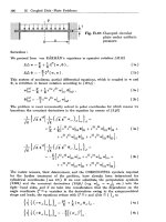
13.1 The Mitsubishi Process (Fig. 13.1, Tables 13.1
And
13.2)
The Mitsubishi process employs three furnaces connected by continuous gravity
flows of molten material. They are:
smelting furnace
electric slag cleaning furnace
converting furnace
The
smelting
furnace blows oxygen-enriched air, dried concentrates, Si02 flux
and recycles into the furnace liquids via vertical lances, Fig.
13.1.
It oxidizes the
Fe
and
S
of
the concentrate to produce
-68%
Cu matte and Fe-silicate slag.
Its
matte and slag flow together into the electric slag cleaning furnace.
The
electric
slag-cleaning furnace separates the smelting furnace's matte and
slag. Its matte flows continuously to the converting furnace. Its slag
(0.7-0.9%
Cu)
flows continuously to water granulation and sale or stockpile.
The
converting
furnace blows oxygen-enriched air, CaCO, flux and granulated
converter slag 'coolant' into the matte via vertical lances. It oxidizes the matte's
Fe and
S
to make molten copper. The copper continuously exits the furnace into
one of
two
holding furnaces for subsequent fire- and electrorefining. The slag
(14%
Cu) flows continuously into a water granulation system. The resulting slag
granules are recycled to the smelting furnace for
Cu
recovey and the converting
furnace for temperature control.
A
major advantage of the process is its effectiveness in capturing
SO2.
It
produces
two
continuous strong
SOz
streams, which are combined to make
excellent feed gas for sulfuric acid or liquid
SO2
manufacture.
Also,
the absence
of crane-and-ladle transport of molten material minimizes workplace emissions.
These environmental advantages plus recent improvements in productivity make
the Mitsubishi process well worth examining for new copper smelting projects.
13.2 Smelting Furnace Details
Fig.
13.2
shows details
of
the Mitsubishi smelting furnace. Solid particulate feed
and oxidizing gas are introduced through
9
vertical lances in
two
rows across the
top of the furnace. Each lance consists of
two
concentric pipes inserted through
the furnace roof. The diameter of the inside pipe is
5
cm
-
the diameter of the
outside pipe,
10
cm. Dried feed is air-blown from bins through the central pipe;
oxygen-enriched air
(55
volume%
02)
is blown through the annulus between the
pipes. The outside pipes are continuously rotated (7-8 rpm) to prevent them
from sticking to their water-cooled roof collars.
202
Extractive Metallurgy
of
Copper
u)
D
e
c
a,
w
-
I
a,
Y
+++++
++
++
A4itsubishi Continuous SmeltingKonverting
203
The outside pipes extend downward to -0.7 m above the molten bath
-
the inside
pipes
to
the furnace roof or
just
above. The outside pipes are high chromium
steel (27% Cr)
-
they burn back -0.4 m per day and are periodically slipped
downward to maintain their specified tip positions. New 3 m sections are
welded to the top
of
the shortened pipes to maintain continuous operation.
The
inside pipes are 304 stainless steel. They do not wear back because their tips are
high above the reaction zone.
Concentrate/flux/recycle
feed meets oxidizing gas at the exit
of
the inside pipe.
The mixture jets onto the molten bath to form a matte-slag-gas foandemulsion in
which liquids, solids and gas react with each other to form matte and slag. These
continuously overflow together through a taphole and down a sloped launder
into the electric slag-cleaning furnace.
The offgas (25-30 volume%
SOz)
from the oxidation reactions
is
drawn up a
large uptake. It passes through waste heat boilers, electrostatic precipitators and
a wet gas cleaning system before being pushed into a sulfuric acid or liquid
SO1
plant.
13.3
Electric Slag Cleaning Furnace Details
The electric slag-cleaning furnace (3600 kW) is elliptical with three or six
graphite electrodes in one or
two
rows along the long axis. It accepts matte and
slag from the smelting furnace and separates them into layers.
Matte continuously underflows from its layer out
of
the electric furnace and into
the converting furnace.
A
siphon and launder system is used. Slag continuously
overflows through
a
taphole. It is granulated in flowing water and sold or
stockpiled. Residence times in the furnace are
1
to 2 hours.
The purpose of the electrodes and electrical power
is
to keep the slag hot and
fluid. Heat is obtained by resistance to electric current flow between the
graphite electrodes in the slag
-
selectively heating the slag to 1250°C.
Only a tiny amount of offgas is generated in the clcctric furnace. It is collected
from the slag taphole hood, drawn through an electrostatic precipitator and
vented to atmosphere.
13.4
Converting Furnace Details
The converting furnace continuously receives matte from the electric slag-
cleaning furnace. It blows oxygen-enriched air blast
(30-35
volume%
Oz),
CaC03 flux and converter slag granules
onto
the surface
of
the matte. It also
receives considerable copper scrap including scrap anodes.
204
Extractive Metallurgy
of
Copper
Table
13.1.
Physical details
of
three Mitsubishi coppermaking systems,
2001.
Figs.
13.2
and
10.1
show diagrams
of
the furnaces.
Mitsubishi
PT
Smelting
Materials
Corp.
co.
LG Nikko
Naoshima,
Gresik, Onsan,
Japan
Indonesia Korea
Smelter
Furnace commissioning date
Copper production rate, tonnedday
Smelting furnace
shape
diameter
x
height (inside brick),
m
number of lances
outside pipe diameter, cm
inside pipe diameter, cm
lance rotations per minute
slag layer thickness,
m
matte layer thickness,
m
liquids, offgas temperature,
"C
Electric slag cleaning furnace
power rating, kW
shape
width
x
lenglh
x
height,
ni
electrodes
material
number
diameter,
m
immersion in slag, m
voltage between electrodes,
V
current between electrodes, kA
applied power, kW
slag layer thickness, m
matte layer thickness, m
matte, slag, offgas temperatures,
"C
estimated slag residence time, hours
Converting furnace
shape
diameter
x
height,
m
number of lances
outside pipe diameter, cm
inside pipe diameter, cm
lance rotations per minute
slag layer thickness,
m
copper layer thickness,
in
copper, slag, offgas temperature,
"C
1991
900
to
1000
circular
10x4
9
ID:
10
ID:
5
7.7
0.1
1.4
1225- 1240,
1225-1240
3600
elliptical
6.0~ 12.5~2.0
graphite
6
0.4
0.5
90
to
120
10.5
to
12.0
2400
0.6
0.45
1210, 1250,
-
-1
circular
8.0
x
3.6
10
ID:
10
ID:
5
7.7
0.12
0.97
1220, 1235,
1235
1998
-750
circular
10.1
x
4
9
10
5
6.5
0.1
1.4
1240, 1240
2 100(No.
I);
1500 (No.2)
elliptical
5.9~12.5~2.0
graphite
6
0.4
0.2
to
0.3
90
to
120
6.5(No.l);
5.5 (No.2)
3000
0.45
0.65
1230, 1270,
-
1
to
2
circular
9.0
x
3.7
10
10,9
5
6.5
0.15
1.1
1220, 1235,
1998
800
circular
IO
x
4
9
SxlOcm,
2x9cm
5
7.8
0.1
1.4
1240, 1250
3600
elliptical
6.0~12.5~2.0
graphite
6
0.4
0.5
to
0.6
80
to
100
5.5
to 7.0
1700
0.60
0.45
1220, 1250,
1000
1
to
2
circular
8.1
x
3.6
10
8xlOcm,
2x8.2cm
5
7.8
0.13
0.96
1220, 1240,
1230 1250
Mitsubishi Continuous Smelting/Converting
205
Table
13.2.
Operating data
for
three Mitsubishi coppermaking systems,
2001.
Smelter
Smelting furnace
Naoshima, Japan Gresik, Indonesia Onsan, Korea
Inputs,tonnes/day
concentrate
silica flux
limestone flux
granulated converting furnace slag
smelting furnace dust
converting furnace dust
other:
Blast
volume%
02
input rate, Nm’/minute
oxygen, tonndday
Hydrocarbon
Fuel
(coal, tonnes/day)
Output
offgas
volume%
SO2
(entering boiler)
flowrate, Nm’/minute
dust tonnedday
Electric Slag Cleaning Furnace
Inputs
outputs
matte, tonneslday
matte
%Cu
slag, tonnedday
slag %Cu
slag %Si02/%Fe
offgas, Nm’/minute (ppm
SO?)
kWh consumptiodtonne of slag
Converting Furnace (autothermal)
Inputs, tonnedday
matte from electric furnace
limestone flux
granulated converting furnace slag
anode scrap copper
purchased scrap copper
volume%
02
input rate, Nm’/minute
oxygen, tonnedday
copper, tonneslday
copper,
%Cu
copper,
%O
copper,
%S
slag, tonnedday
slag,
%Cu
slag, mass% CaO/mass% Fe
offgas, Nm’/minute
volume%
SO2
Blast
outputs
2300 (34%
Cu)
340
42
240
67
61
5
compressed
copper scrap
56
540
500
63
34
560
67
2000
to
2300 (31.7%
Cu)
300
to
400
35
I60
to
180
60
60
40
sludge from
wastewater
treatment plant
50
to
55
600
to
650
90
30
600
to
650
60
2109 (33.2%
Cu)
386 (82%
SO2)
52
96
60
60
14
reverts
45
to
55
600
450 (99%
02)
140
31
570
60
matte and slag from smelting furnace
1400
68
1300
0.7
0.9
42
1400
50
360
120
34
35
490
180
900
to
1000
98.4
0.3
0.7
600
14
0.4
480
31
1270
68
1450
0.7
0.8
55
1270
30
I60
to
180
95
to
100
0
25
to
28
460
to
470
850
to
900
98.5
0.3
0.7
I60
to
180
14
0.4
450
25
1018
68.8
1331
0.8
0.9
30
500
(<I50
ppm)
1018
69
246
78
44
32
to
35
430
133
(99%
02)
820
98.5
0.9
360
I5
0.34
410
24
206
Extractive Metallurgy
of
Copper
It produces:
(a) molten copper,
-0.7%
S
(b) molten slag,
14%
Cu
(c) SO2 bearing offgas,
25-30
volume% S02.
The molten copper continuously departs the furnace through a siphon and
launder into one
of
two
anode furnaces, Fig 13.1. The slag continuously
overflows into a water-granulation system. The offgas is drawn through a large
uptake, waste heat boiler, electrostatic precipitators and a wet gas cleaning
system before being pushed into
a
sulfuric acid
or
liquid SO2 plant. The
smelting and converting offgases are combined prior to entering the electrostatic
precipitators.
The oxygen-enriched air and solids are introduced into the furnace through
10
lances like the smelting furnace lances. The tips of the outside pipes are
0.3
to
0.8
m above the bath
-
the inside pipe tips above
or
just through the
roof.
The
outer pipes are continuously rotated
to
prevent them from sticking to their roof
collars. They are also slowly slipped downwards
as
they bum back.
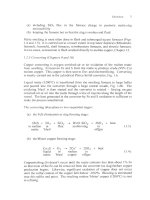
13.4.
I
Converting furnace slag
A
unique feature
of
Mitsubishi converting is its CaO-based (rathcr than SiOz
based) slag (Yazawa
et
aZ.,
1981;
Goto
and Hayashi,
1998).
Early in the
development
of
the process, it was found that blowing strong
02
'blast' onto the
surface
of
SO2-based slag made a crust
of
solid magnetite. This made hrther
converting impossible. CaO, on the other hand, reacts with solid magnetite,
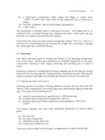
molten Cu and O2 to form a liquid CaO-Cu20-Fe0, slag, Fig. 13.3. The slag
typically contains:
12-
16%
Cu
(-60%
as
Cu20,
balance Cu)
40-55%
Fe
(-70%
as Fe+++, balance Fe")
1520% CaO.
Its viscosity is -10.' kg/m.s (Wright
et
al.,
2000).
13.4.2
Converting furnace
copper
Mitsubishi copper contains more
S
than Peirce-Smith converter copper,
-0.7%
vs.
-0.02%.
The only disadvantage of this is a longer oxidation period in the
anode furnace. The
S
content can be lowered in the Mitsubishi converter by
supplying more
02,
but this increases the amount of Cu in slag.
0.7%
-
0.8%
S
in copper seems optimum.
Mitsubishi Continuous Smelting/Converting
207
1300°C
1200°C
60
CaO
melt
_
~~~~~~~
cuzo
20 40 60
80
FeO,
mass%
FeO,
Fig.
13.3.
Liquidus lines
at
1200°C
and
1300°C
for
Ca0-Cu20-Fe0.
slags
in air,
1
atmosphere pressure (Yazawa and Eguchi,
1976;
Goto
and Hayashi,
1998). The
triangle
represents Mitsubishi converting furnace slag if
all
its
Cu
exists
as
Cu20.
Slag
compositions inside
the
solid
line
are
fully
liquid
at
13OOOC.
Slag compositions
inside
the
dashed lines are
fully
liquid
at
1200°C.
13.5
Recent
Mitsubishi
Process Developments
The 1980’s and 1990’s saw a doubling
of
Mitsubishi smelting rates (Newman
et
ai.,
1992, 1993). This has greatly improved the competitive position
of
the
process. The changes that have enhanced productivity and competitiveness have
been:
(a) increased oxygen enrichment
of
the smelting and converting furnace
blasts
(b)
improvements in furnace refractories and water-cooling, which have
enhanced reliability and extended furnace campaign life (Majumdar
et
al.,
1997)
(c) better measurements
of
temperature and lance tip position plus improved
computer control
(d) bending of recycle scrap anodes to prevent mechanical damage to the
firnace hearth (Oshima
et
al.,
1998).
Converting furnace life was extended at the Timmins smelter by avoiding
impingement
of
lance gas and solids
on
the furnace hearth (Majumdar
et
al.,
1997).
Impingement was avoided by:
(a) increasing the lance diameter
to
reduce gas/solids velocity
(b)
maintaining the lances at
0.6
or
0.7
m above the bath
208
Extractive Metallurgy
of
Copper
(c) feeding abrasive solids (e.g. converter slag granules) through low velocity
bypass lances.
Innovations have also been made
in
the new Naoshima smelter to enable the
smelting and converting furnaces to melt large quantities of scrap copper
(Oshima
et al.,
1998;
Shibasaki
et
al.,
1991, 1992,
1993).
This scrap melting
capability has considerably enhanced the versatility of the process.
13.6
Reaction Mechanisms in Mitsubishi Smelting
13.6.
I
Smelting furnace
The velocities of solids and gas leaving Mitsubishi smelting hace lances are
130-150
dsecond (Goto and Hayashi,
1998).
Times of flight
of
the particles
across the
0.7
m distance between lance tip and melt surface are, therefore, on
the order of
1
0-3
to
10’
seconds. The temperature rise of the gadsolid jet during
this time
is
calculated to be
-50°C.
This is not enough to cause ignition of the
concentrate. Consequently, melting and oxidation of concentrate particles
occurs entirely after entry into the gas-slag-matte foademulsion beneath the
lances (Goto and Hayashi,
1998;
Asaki
et
al.,
2001).
Industrial evidence indicates that the smelting furnace contains mainly matte
(1.2-
1.5
m deep) with a gas/slag/matte foademulsion beneath the lances (Goto
and Echigoya,
1980,
Shibasaki and Hayashi,
1991).
Away from the lances,
S02&
gas disengages from the foam and the matte and slag begin to separate.
Newly formed slag (-0.05 m thick and containing some entrained matte) flows
toward the taphole where
it
overflows. Matte also continuously overflows as
new matte is made under the lances.
13.6.2
Electric slag cleaning furnace
The electric slag cleaning furnace accepts molten matte and slag from the
smelting furnace. These liquids separate and form
two
layers in the furnace
-
a
bottom layer
of
matte
0.5
-
0.8
m
thick, and a top layer of slag
-0.5
m thick. The
residence times
of
the liquids are
1
or
2
hours. These times,
plus
electromagnetic stimng in the furnace allow the slag and matte to approach
equilibrium. Passage of electricity through the slag ensures that the slag is hot
and fluid. This, in turn, creates conditions for efficient settling
of
matte droplets
from the slag.
The slag is the main route of Cu
loss
from the smelter. It is important, therefore,
that the total amount of Cu-in-slag be minimized. This is done by:
(a) maximizing slag residence time
in
the electric furnace (to maximize matte
settling)
Mitsubishi Continuous SmeltingKonverting
209
(b) keeping the slag hot, fluid and quiescent
(c) minimizing slag mass (per tonne
of
Cu) by smelting high Cu grade
concentrates and minimizing fluxing
(d) optimizing slag composition
to
minimize slag viscosity and density.
13.6.3
Converting
furnace
The converting furnace blows oxygen-enriched air, CaC03 flux and recycle
converter slag granules through ten roof lances. The velocity of the gadsolid
mix is typically 120 dsecond.
02
is supplied to the furnace at the exact rate
which will produce metallic copper from the incoming matte.
The furnace contains a thin
(-0.1
m) layer of slag on top of about
1
m of molten
copper. The solids and gas from the lance penetrate through the slag and deep
into the copper.
The furnace is operated with an excess of
O2
to
avoid the presence of a
permanent molten matte layer in the furnace. This reduces the risk of slag
foaming, Section 12.5.1. The absence of a permanent matte layer is indicated by
0.7%
S
in
the converter's copper rather than
1%
S
which would be at equilibrium
with a Cu2S layer.
Likely converting mechanisms are:
(a) matte flows continuously into the furnace and spreads out on the furnace's
(b)
it
reacts with
O2
under the lances to make FeO and molten copper by the
permanent layer of molten copper
reactions:
3
FeS
+
+
FeO
+
SO2
(13.1)
in matte in slag
cu2s
+
02
+
2CU"
+
so2
(13.2).
(c) the above mentioned excess
O2
leads
to
over-oxidation
of
Cu and FeO by
in matte
the reactions:
1
3Fe0
+
,02
+
Fe304
in slag
1
2cu
+
?O*
+
cu*o
in slag
(13.3)
(13.4).
210
Extractive
Metallurgy
ofcopper
(d) Cu20, FeO and Fe304 are slagged by the reactions:
CaC03
+
CaO
+.
C02
from lance
CaO+Cu20+FeO+Fe304
+
moltenslag
(-
15%Ca0, 15% Cu,
15%Fef+,35%Fe+++)
This slag probably reacts with matte by reactions like:
3Fe3O4
+
FeS
+
lOFeO
+
SO2
in slag in matte
2Fe304
+
Cu2S
+
2Cu"
+
6Fe0
+
SO2
in slag in matte
2C~20
+
CU~S
+
~CU"
+
SO2
in slag in matte
(13.5)
(13.6).
(13.7)
(13.8)
(13.9).
The relative importance of direct oxidation (by
02)
and indirect oxidation (by
slag) is a matter of conjecture.
13.7
Optimum Matte Grade
The Cu grade
of
the matte being produced by the smelting furnace (and flowing
into the converting furnace) is chosen as a balance between:
(a) the amount of Cu lost in the discard slag from the electric furnace, Fig.
(b) the amount of granulated high-Cu slag which must be recycled back from
(c) the amount of coal which must be added to the smelting furnace and the
4.6
the converting furnace to the smelting furnace
amount of coolant which must be added to the converting furnace.
The optimum matte grade for the Mitsubishi process is 68% Cu. With this matte
grade, the discard slag from the electric slag cleaning furnace contains 0.7-0.9%
Cu and converter slag recycle is
0.1
to 0.3 tonnes per tonne of concentrate feed,
Table
13.2.
13.8
Impurity Behavior in Mitsubishi SmeltinglConverting
Table
13.3
quantifies impurity behavior at the Naoshima and Timmins smelters.
Mitsubishi
Continuous Smelting/Converting
2
1
I
It
shows that Mitsubishi copper contains a significant fraction of impurities
(except Zn), but that the fraction can be decreased by not recycling electrostatic
precipitator dust.
Table
13.3.
Distribution
of
impurities
to
anodes during Mitsubishi smelting/converting.
The
Naoshima data are
from
Shibasaki and Hayashi, 1991, Nagano, 1985 and
Goto
and
Hayashi, 1998.
The
Timrnins
data
are
from
Newman
et
al.,
1991.
Process
%
of
impurity-in-feed reporting
to anode copper
As
Bi
Pb
Se
Sb
Zn
Naoshima Mitsubishi smeltingkonverting
with
21
34
42
87
45
0.2
complete dust recycle
Naoshima Mitsubishi smeltingkonverting,
4 15 15
15
0
Timmins Mitsubishi smelting/converting,
11
55
electrostatic precipitator dust not recycled
electrostatic precipitator dust sent
to
Zn plant
13.9
Process Control in Mitsubishi SmeltingKonverting
(Goto
and Hayashi,
1998)
Bath temperature is the most important control parameter in the Mitsubishi
process. Maintaining an optimum temperature ensures good slag and matte
fluidity while at the same time minimizing refractory erosion. Typical operating
temperatures at the Naoshima smelter are shown in Table 13.4.
Table 13.4 shows that the electric slag cleaning furnace slag is operated hotter
than the smelting furnace mattelslag. This is done to avoid precipitation
of
solid
Fe304
and/or SO2.
Precipitation
of
Fe304 has been found to cause formation of a “muddy layer”
between molten matte and molten slag.
This layer prevents good mattelslag
separation. It results in high matte entrainment in the discard slag, hence high
Cu-in-slag losses.
Precipitation of Si02 produces Si02 rich “floating solids”. These solids (-10%
Cu) do
not
settle into the matte layer and result
in
high Cu-in-slag losses.
13.9.
I
Mitsubishiprocess control
Process control at Naoshima combines quantitative and qualitative process
information, Tables
13.5
and 13.6. The quantitative information is continuously
inputted into an expert type computer control system.