CompTIA A+ Complete Study Guide phần 2 pdf
Bạn đang xem bản rút gọn của tài liệu. Xem và tải ngay bản đầy đủ của tài liệu tại đây (4.44 MB, 98 trang )
28
Chapter 1
Identifying Personal Computer Components
You can easily identify which component inside the computer is the CPU because it is a
large square lying flat on the motherboard with a very large heat sink and fan (as shown earlier
in Figure 1.10). Or if the CPU is installed in a Slot 1 motherboard, it is a large
1
⁄
2
-inch-thick
expansion card with a large heat sink and fan integrated into the package. It is located away
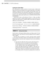
from the expansion cards. Figure 1.24 shows the location of the CPU in relation to the other
components on a typical ATX motherboard. Notice how prominent the CPU is.
FIGURE 1.24 The location of a CPU inside a typical computer
Modern processors can feature the following:
Hyperthreading This term refers to Intel’s Hyper-Threading Technology (HTT). HTT is a
form of simultaneous multithreading (SMT). SMT takes advantage of a modern CPU’s super-
scalar architecture. Superscalar processors are able to have multiple instructions operating on
separate data in parallel.
HTT-capable processors appear to the operating system to be two processors. As a result, the
operating system can schedule two processes at the same time, as in the case of symmetric mul-
tiprocessing (SMP), where two or more processors use the same system resources. In fact, the
operating system must support SMP in order to take advantage of HTT. If the current process
stalls because of missing data caused by, say, cache or branch prediction issues, the execution
resources of the processor can be reallocated for a different process that is ready to go, reduc-
ing processor downtime.
Multicore A processor that exhibits a multicore architecture has two completely separate pro-
cessors in the same package. Whether there are multiple dies in the same package or the single
4831x.book Page 28 Tuesday, September 12, 2006 11:59 AM
Identifying Purposes and Characteristics of Processors
29
die contains the equivalent circuitry of multiple processors, the operating system can treat the
single processor as if it were two separate processors. As with HTT, the operating system must
support SMP. In addition, SMP is not an enhancement if the applications run on the SMP system
are not written for parallel processing. Dual-core processors are a common specific case for the
multi-core technology.
Throttling CPU throttling, or clamping, is the process of controlling how much CPU time is
spent on an application. By controlling how individual applications use the CPU, all applica-
tions are treated more fairly. The concept of application fairness becomes a particular issue in
server environments, where each application could represent the efforts of a different user.
Thus, fairness to applications becomes fairness to users, the real customers. Clients of today’s
terminal servers benefit from CPU throttling.
Microcode Microcode is the set of instructions (known as an instruction set) that make up
the various microprograms that the processor executes while carrying out its various duties.
The Multimedia Extensions (MMX) microcode is a specialized example of a separate micro-
program that carries out a particular set of functions. Microcode is at a much lower level than
the code that makes up application programs. Each instruction in an application will end up
being represented by many microinstructions, on average. The MMX instruction set is incor-
porated into most modern CPUs from Intel and others. MMX came about as a way to take
much of the multimedia processing off the CPU’s hands, leaving the processor to other tasks.
Think of it as sort of a coprocessor for multimedia, much like the floating-point unit (FPU) is
a math coprocessor.
Overclocking Overclocking your CPU offers increased performance, on par with a proces-
sor designed to operate at the overclocked speed. However, unlike with the processor designed
What’s Your CPU?
The surest way to determine which CPU your computer is using is to open the case and view
the numbers stamped on the CPU, which today requires removal of the active heat sink. How-
ever, you may be able to get an idea without opening the case and removing the heat sink and
fan, because many manufacturers indicate the type of processor by placing a very obvious
sticker somewhere on the case indicating the processor type. Failing this, you can always go
to the manufacturer’s website and look up the information on the model of computer you
have. If you have a no-name clone, there is always the System Information dialog found by
right-clicking My Computer and selecting Properties. The General tab, which is the default,
contains such information.
Another way to determine a computer’s CPU is to save your work, exit any open programs,
and restart the computer. Watch closely as the computer returns to its normal state. You
should see a notation that tells you what chip you are using.
4831x.book Page 29 Tuesday, September 12, 2006 11:59 AM
30
Chapter 1
Identifying Personal Computer Components
to run that fast, you must make special arrangements to ensure that an overclocked CPU does
not destroy itself from the increased heat levels. An advanced cooling mechanism, such as
liquid cooling, might be necessary to avoid losing the processor and other components.
Cache As mentioned in the “Memory Slots and External Cache” section earlier in this chapter,
cache is a very fast chip memory that is used to hold data and instructions that are most likely
to be requested next by the CPU. The cache located on the CPU is known as L1 cache and is gen-
erally smaller in comparison to L2 cache, which is located on the motherboard. When the CPU
requires outside information, it believes it requests that information from RAM. The cache con-
troller, however, intercepts the request and consults its tag RAM to discover if the requested
information is already cached, either at L1 or L2. If not, a cache miss is recorded and the infor-
mation is brought back from the much slower RAM, but this new information sticks to the L1
and L2 cache on its way to the CPU from RAM.
Voltage Regulator Module The voltage regulator module (VRM) is the circuitry that sends
a standard voltage level to the portion of the processor that is able to send a signal back to the
VRM concerning the voltage level the CPU needs. After receiving the signal, the VRM truly
regulates the voltage to steadily provide the requested voltage.
Speed The speed of the processor is generally described in clock frequency (MHz or GHz).
There can be a discrepancy between the advertised frequency and the frequency the CPU uses
to latch data and instructions through the pipeline. This disagreement between the numbers
comes from the fact that the CPU is capable of splitting the clock signal it receives from the
oscillator into multiple regular signals for its own use.
32- and 64-Bit System Bus The set of data lines between the CPU and the primary memory
of the system can be 32 or 64 bits wide, among other widths. The wider the bus, the more data
that can be processed per unit of time, and hence the more work that can be performed. Inter-
nal registers in the CPU might be only 32 bits wide, but with a 64-bit system bus, two separate
pipelines can receive information simultaneously.
Identifying Purposes and Characteristics
of Memory
“More memory, more memory, I don’t have enough memory!” Today, memory is one of the
most popular, easy, and inexpensive ways to upgrade a computer. As the computer’s CPU
works, it stores information in the computer’s memory. The rule of thumb is the more memory
a computer has, the faster it will operate.
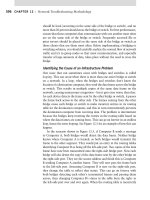
To identify memory within a computer, look for several thin rows of small circuit boards
sitting vertically, packed tightly together near the processor. Figure 1.25 shows where memory
is located in a system.
4831x.book Page 30 Tuesday, September 12, 2006 11:59 AM
Identifying Purposes and Characteristics of Memory
31
FIGURE 1.25 Location of memory within a system
Parity checking is a rudimentary error-checking scheme that lines up the chips in a column
and divides them into an equal number of bits, numbered starting at 0. All the number n bits,
one from each chip, form a numerical set. If even parity is used, for example, the number of
bits in the set is counted up, and if the total comes out even, then the parity bit is set to 0,
because the count is already even. If it comes out odd, then the parity bit is set to 1 to even up
the count. You can see that this is effective only for determining if there was a blatant error
in the set of bits, but there is no indication as to where the error is and how to fix it. This is
error checking, not error correction. Finding an error can lock up the entire system and display
a memory parity error. Enough of these errors and you need to replace the memory. If that
doesn’t fix the problem, good luck.
In the early days of personal computing, almost all memory was parity-based. Compaq was
one of the first manufacturers to employ non-parity RAM in their mainstream systems. As
quality has increased over the years, parity checking in the RAM subsystem has become rarer.
If parity checking is not supported, there will generally be fewer chips per module, usually one
less per column of RAM.
The next step in the evolution of memory error detection is known as Error Checking and
Correcting (ECC). If memory supports ECC, check bits are generated and stored with the
data. An algorithm is performed on the data and its check bits whenever the memory is
accessed. If the result of the algorithm is all zeros, then the data is deemed valid and processing
continues. ECC can detect single- and double-bit errors and actually correct single-bit errors.
In the following sections, we’ll outline the four major types of computer memory—DRAM,
SRAM, ROM, and CMOS—as well as memory packaging.
4831x.book Page 31 Tuesday, September 12, 2006 11:59 AM
32
Chapter 1
Identifying Personal Computer Components
DRAM
DRAM is dynamic random access memory. (This is what most people are talking about when they
mention RAM.) When you expand the memory in a computer, you are adding DRAM chips. You
use DRAM to expand the memory in the computer because it’s cheaper than any other type of
memory. Dynamic RAM chips are cheaper to manufacture than other types because they are less
complex. Dynamic refers to the memory chips’ need for a constant update signal (also called a
refresh signal) in order to keep the information that is written there. If this signal is not received
every so often, the information will cease to exist. Currently, there are four popular implementa-
tions of DRAM: SDRAM, DDR, DDR2, and RAMBUS.
SDRAM
The original form of DRAM had an asynchronous interface, meaning that it derived its clocking
from the actual inbound signal, paying attention to the electrical aspects of the waveform, such
as pulse width, to set its own clock to synchronize on the fly with the transmitter. Synchronous
DRAM (SDRAM) shares a common clock signal with the transmitter of the data. The com-
puter’s system bus clock provides the common signal that all SDRAM components use for each
step to be performed.
This characteristic ties SDRAM to the speed of the FSB and the processor, eliminating the
need to configure the CPU to wait for the memory to catch up. Every time the system clock
ticks, one bit of data can be transmitted per data pin, limiting the bit rate per pin of SDRAM
to the corresponding numerical value of the clock’s frequency. With today’s processors inter-
facing with memory using a parallel data-bus width of 8 bytes (hence the term 64-bit proces-
sor), a 100MHz clock signal produces 800MBps. That’s megabytes per second, not megabits.
Such memory is referred to as PC100, because throughput is easily computed as eight times
the rating.
DDR
Double Data Rate (DDR) SDRAM earns its name by doubling the transfer rate of ordinary
SDRAM by double-pumping the data, which means transferring it on both the rising and
falling edges of the clock signal. This obtains twice the transfer rate at the same FSB clock
frequency. It’s the rising clock frequency that generates heating issues with newer compo-
nents, so keeping the clock the same is an advantage. The same 100MHz clock gives a DDR
SDRAM system the impression of a 200MHz clock in comparison to a single data rate
(SDR) SDRAM system.
You can use this new frequency in your computations or simply remember to double your
results for SDR calculations, producing DDR results. For example, with a 100MHz clock, two
operations per cycle, and 8 bytes transferred per operation, the data rate is 1600MBps. Now
that throughput is becoming a bit tricker to compute, the industry uses this final figure to
name the memory modules instead of the frequency, which was used with SDR. This makes
the result seem many times better, while it’s really only twice as good. In this example, the
module is referred to as PC1600. The chips that go into making PC1600 modules are named
after the perceived double-clock frequency: DDR-200.
4831x.book Page 32 Tuesday, September 12, 2006 11:59 AM
Identifying Purposes and Characteristics of Memory
33
Referring to the original SDRAM as SDR, or single data rate SDRAM, is similar
to retrospectively referring to The Great War as World War I only after the
start of World War II.
DDR2
Think of the 2 in DDR2 as yet another multiplier of 2 in the SDRAM technology, using a
lower peak voltage to keep power consumption down (1.8V vs. the 2.5V of DDR and others).
Still double-pumping, DDR2, like DDR, uses both sweeps of the clock signal for data transfer.
Internally, DDR2 further splits each clock pulse in two, doubling the number of operations it
can perform per FSB clock cycle. Through enhancements in the electrical interface and buffers,
as well as through adding off-chip drivers, DDR2 nominally produces four times what SDR
is capable of producing.
However, DDR2 suffers from enough additional latency over DDR that identical throughput
ratings find DDR2 at a disadvantage. Once frequencies develop for DDR2 that do not exist for
DDR, however, DDR2 could become the clear SDRAM leader, although DDR3 is nearing
release. Continuing the preceding example and initially ignoring the latency issue, DDR2 using
a 100MHz clock transfers data in four operations per cycle and still 8 bytes per operation, for
a total of 3200MBps.
Just like DDR, DDR2 names its chips based on the perceived frequency. In this case, you
would be using DDR2-400 chips. DDR2 carries on the final-result method for naming modules
but cannot simply call them PC3200 modules because those already exist in the DDR world.
DDR2 calls these modules PC2-3200. The latency consideration, however, means that DDR’s
PC3200 offering is preferable to DDR2’s PC2-3200. After reading the “RDRAM” section, con-
sult Table 1.2, which summarizes how each technology in the “DRAM” section would achieve
a transfer rate of 3200MBps, even if only theoretically. For example, SDR PC400 doesn’t exist.
TABLE 1.2 How Each Memory Type Transfers 3200MBps
Memory Type
Actual/Perceived Clock
Frequency (MHz) Bytes per Transfer
SDR SDRAM PC400* 400/400 8
DDR SDRAM PC3200 200/400 8
DDR2 SDRAM PC2-3200 100/400 8
RDRAM PC800 400/800 4**
* SDR SDRAM PC400 does not exist.
** Running in 32-bit dual-channel mode.
4831x.book Page 33 Tuesday, September 12, 2006 11:59 AM
34
Chapter 1
Identifying Personal Computer Components
RDRAM
Rambus DRAM, or Rambus Direct RAM (RDRAM), named for the company that designed
it, is a proprietary synchronous DRAM technology. RDRAM can be found in fewer new sys-
tems today than just a few years ago. This is because Intel once had a contractual agreement
with Rambus to create chipsets for the motherboards of Intel and others that would primarily
use RDRAM in exchange for special licensing considerations and royalties from Rambus. The
contract ran from 1996 until 2002. In 1999, Intel launched the first motherboards with
RDRAM support. Until then, Rambus could be found mainly in gaming consoles and home
theater components. RDRAM did not impact the market as Intel had hoped, and so mother-
board manufacturers got around Intel’s obligation by using chipsets from VIA Technologies,
leading to the rise of that company.
Although other specifications preceded it, the first motherboard RDRAM model was known
as PC800. As with non-RDRAM specifications that use this naming convention, PC800 specifies
that, using a faster 400MHz clock signal and double-pumping like DDR/DDR2, an effective fre-
quency of 800MHz and a transfer rate of 800Mbps per data pin are created. PC800 uses only a
16-bit (2-byte) bus called a channel, exchanging a 2-byte packet during each read/write cycle, still
bringing the overall transfer rate to 1600MBps per channel because of the much higher clock rate.
Modern chipsets allow two 16-bit channels to communicate simultaneously for the same read/
write request, creating a 32-bit dual-channel. Two PC800 modules in a dual-channel configuration
produce transfer rates of 3200MBps.
Today, RDRAM modules are also manufactured for 533MHz and 600MHz bus clock fre-
quencies and 32-bit dual-channel architectures. Termed PC1066 and PC1200, these models
produce transfer rates of 2133 and 2400MBps per channel, respectively, making 4266 and
4800MBps per dual-channel. Rambus has road maps to 1333 and 1600MHz models. The sec-
tion “RIMM” in this chapter details the physical details of the modules.
Despite RDRAM’s performance advantages, it has some drawbacks that keep it from tak-
ing over the market. Increased latency, heat output, complexity in the manufacturing process,
and cost are the primary shortcomings. PC800 RDRAM had a 45ns latency, compared to only
7.5ns for PC133 SDR SDRAM. The additional heat that individual RDRAM chips put out led
to the requirement for heat sinks on all modules. High manufacturing costs and high licensing
fees led to triple the cost to consumers over SDR, although today there is more parity between
the prices.
In 2003, free from its contractual obligations to Rambus, Intel released the i875P chipset.
This new chipset provides support for a dual-channel platform using standard PC3200 DDR
modules. Now, with 16 bytes (128 bits) transferred per read/write request, making a total
transfer rate of 6400MBps, RDRAM no longer holds the performance advantage it once did.
SRAM
The S in SRAM stands for static. Static random access memory doesn’t require a refresh signal
like DRAM does. The chips are more complex and are thus more expensive. However, they
are faster. DRAM access times come in at 60 nanoseconds (ns) or more; SRAM has access
times as fast as 10ns. SRAM is often used for cache memory.
4831x.book Page 34 Tuesday, September 12, 2006 11:59 AM
Identifying Purposes and Characteristics of Memory
35
ROM
ROM stands for read-only memory. It is called read-only because the original form of this
memory could not be written to. Once information had been written to the ROM, it couldn’t
be changed. ROM is normally used to store the computer’s BIOS, because this information
normally does not change very often.
The system ROM in the original IBM PC contained the power-on self-test (POST), Basic
Input/Output System (BIOS), and cassette BASIC. Later IBM computers and compatibles
include everything but the cassette BASIC. The system ROM enables the computer to “pull
itself up by its bootstraps,” or boot (start the operating system).
Through the years, different forms of ROM were developed that could be altered. The first
generation was the programmable ROM (PROM), which could be written to for the first time
in the field, but then no more. Following the PROM came erasable PROM (EPROM), which
was able to be erased using ultraviolet light and subsequently reprogrammed. These days, our
flash memory is a form of electrically erasable PROM (EEPROM), which does not require UV
light, but rather a slightly higher than normal electrical pulse, to erase its contents.
CMOS
CMOS is a special kind of memory that holds the BIOS configuration settings. CMOS
memory is powered by a small battery, so the settings are retained when the computer is
shut off. The BIOS starts with its own default information and then reads information
from the CMOS, such as which hard drive types are configured for this computer to use,
which drive(s) it should search for boot sectors, and so on. Any conflicting information
read from the CMOS overrides the default information from the BIOS. CMOS memory
is usually not upgradable in terms of its capacity and is very often integrated into the
modern BIOS chip.
Memory Packaging
First of all, it should be noted that each motherboard supports memory based on the speed of
the frontside bus (FSB) and the memory’s form factor. So, for example, if the motherboard’s FSB
is rated at a maximum speed of 533MHz, and you install memory that is rated at 300Mhz, the
memory will operate at only 300MHz, thus making the computer operate slower than what it
could. In their specifications, most motherboards list which type(s) of memory they support as
well as its maximum speeds.
The memory slots on a motherboard are designed for particular module form factors or
styles. In case you run across the older terms, DIP, SIMM, and SIPP are obsolete memory pack-
ages. Terms like double-sided/single-sided memory and dual-bank/single-bank memory are
often confused. When speaking of sides, it is correct to refer to the two physical sides of the
module and whether they contain chips. However, that says nothing of the number of banks
the module satisfies. Satisfying two banks, or channels more often, as in the case of the DDR
4831x.book Page 35 Tuesday, September 12, 2006 11:59 AM
36
Chapter 1
Identifying Personal Computer Components
family, can be accomplished with single-sided memory. The most popular form factors for
primary memory modules today are these:
DIMM
RIMM
SoDIMM
MicroDIMM
DIMM
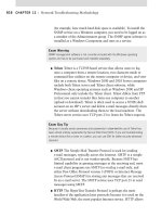
One type of memory package is known as a DIMM. As mentioned earlier in this chapter,
DIMM stands for Dual Inline Memory Module. DIMMs are 64-bit memory modules that are
used as a package for the SDRAM family: SDRAM, DDR, and DDR2. The term dual refers
to the fact that, unlike their SIMM predecessors, DIMMs differentiate the functionality of the
pins on one side of the module from the corresponding pins on the other side. With 84 pins
per side, this makes 168 independent pins on each standard SDRAM module, as shown with
its two keying notches in Figure 1.26.
The DIMM used for DDR memory has a total of 184 pins and a single keying notch, while
the DIMM used for DDR2 has a total of 240 pins, one keying notch, and an aluminum cover
for both sides, called a heat spreader, designed like a heat sink to dissipate heat away from the
memory chips and prevent overheating.
RIMM
Not an acronym, RIMM is a trademark of Rambus Inc., perhaps a clever play on the acronym
DIMM, a competing form factor. A RIMM is a custom memory module that varies in physical
specification based on whether it is a 16-bit or 32-bit module. The 16-bit modules have
184 pins and two keying notches, while 32-bit modules have 232 pins and only one keying
notch, reminiscent of the trend in SDRAM-to-DDR evolution. Figure 1.27 shows the two sides
of a 16-bit RIMM module, including the aluminum heat spreaders.
The dual-channel architecture can be implemented utilizing two separate 16-bit RIMMs or
the newer 32-bit single-module design. Motherboards with the 16-bit single- or dual-channel
implementation provide four RIMM slots that must be filled in pairs, while the 32-bit versions
provide two RIMM slots that can be filled one at a time. A 32-bit RIMM has two 16-bit modules
built in and requires only a single motherboard slot, albeit a physically different slot. So you must
be sure of the module your motherboard accepts before upgrading.
FIGURE 1.26 A Dual Inline Memory Module (DIMM)
4831x.book Page 36 Tuesday, September 12, 2006 11:59 AM
Identifying Purposes and Characteristics of Memory
37
Unique to the use of RIMM modules, a computer must have every RIMM slot occupied. Even
one vacant slot will cause the computer not to boot. Any slot not populated with live memory
requires an inexpensive (usually less than US$5 for the 16-bit version) blank of sorts called a con-
tinuity RIMM, or C-RIMM, for its role of keeping electrical continuity in the RDRAM channel
until the signal can terminate on the motherboard. Think of it like a fusible link in a string of hol-
iday lights. It seems to do nothing, but no light works without it. However, 32-bit modules termi-
nate themselves and do not rely on the motherboard circuitry for termination, so vacant 32-bit
slots require a module known as a continuity and termination RIMM (CT-RIMM).
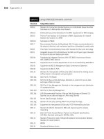
SoDIMM
Notebook computers and other computers that require much smaller components don’t use
standard RAM packages like the SIMM or the DIMM do. Instead, they can use a much smaller
memory form factor called a Small Outline DIMM (SoDIMM). SoDIMMs are available in many
physical implementations, including the older 32-bit (72-pin) configuration and newer 64-bit
(144-pin EDO, 144-pin SDRAM, and 200-pin DDR/DDR2) configurations. Figure 1.28 shows
an example of a 144-pin, 64-bit module.
FIGURE 1.27 A Rambus RIMM module
FIGURE 1.28 144-pin SoDIMM
4831x.book Page 37 Tuesday, September 12, 2006 11:59 AM
38
Chapter 1
Identifying Personal Computer Components
MicroDIMM
The newest, and smallest, RAM form factor is the MicroDIMM. The MicroDIMM is an
extremely small RAM form factor. In fact, it is over 50 percent smaller than a SoDIMM, only
45.5 millimeters (about 1.75 inches) long and 30 millimeters (about 1.2 inches—a bit bigger
than a quarter) wide. It was designed for the ultralight and portable subnotebook style of com-
puter (like those based on the Transmeta Crusoe processor). These modules have 144 pins or
172 pins and are similar to a DIMM in that they use a 64-bit data bus. Often employed in lap-
top computers, SoDIMMs and MicroDIMMs are mentioned in Chapter 3 as well.
Identifying Purposes and Characteristics
of Storage Devices
What good is a computer without a place to put everything? Storage media hold the data
being accessed, as well as the files the system needs to operate and data that needs to be
saved. The many different types of storage differ in terms of their capacity (how much they
can store), access time (how fast the computer can access the information), and the physical
type of media used.
Hard Disk Drive Systems
Hard disk drive (HDD) systems (hard disks or hard drives for short) are used for permanent
storage and quick access (Figure 1.29). Hard disks typically reside inside the computer
(although there are external and removable hard drives) and can hold more information
than other forms of storage.
The hard disk drive system contains three critical components:
Controller Controls the drive. It understands how the drive operates, sends signals to the
various motors in the disk, and receives signals from the sensors inside the drive. Most of
today’s hard disk technologies incorporate the controller and drive into one enclosure.
Hard Disk The physical storage medium. Hard disk drive systems store information on small
disks (between three and five inches in diameter) stacked together and placed in an enclosure.
Host Adapter The translator, converting signals from the hard drive and controller to sig-
nals the computer can understand. Most motherboards today incorporate the host adapter
into the motherboard’s circuitry, offering headers for drive cable connection.
Floppy Drives
A floppy disk is a magnetic storage medium that uses a flexible diskette made of thin plastic
enclosed in a protective casing. The floppy disk once enabled information to be transported
from one computer to another very easily. Today, floppies are a little too small in capacity to
be efficient anymore. They have been replaced by writable CD-ROMs and DVD-ROMs. The
4831x.book Page 38 Tuesday, September 12, 2006 11:59 AM
Identifying Purposes and Characteristics of Storage Devices
39
original term floppy disk referred to the antiquated 8-inch medium used with minicomputers
and mainframes. The original PC floppy diskette, which was 5
1
⁄
4
inches square and known as
a minifloppy diskette, is also obsolete; the microfloppy diskette is a diskette that is 3
1
⁄
2
inches
square. Most computers today use microfloppy diskettes or no floppy at all.
FIGURE 1.29 A hard disk drive system
Generally speaking, throughout this book we will use the term floppy drive to
refer to a 3
1
⁄
2
-inch microfloppy diskette drive.
A floppy drive (shown in Figure 1.30) is used to read and write information to and from
these drives. The advantage of these drives is that they allow portability of data (you can trans-
fer data from one computer to another on a diskette). The downside of a floppy disk drive is
its limited storage capacity. Whereas a hard drive can store hundreds of gigabytes of informa-
tion, most floppy disks were designed to store only about one megabyte. Table 1.3 shows five
different floppy diskette drive formats with their corresponding diskette sizes supported in PC
systems over the years. The following abbreviations are used: DD means double density; HD
means high density; ED means extended density.
TABLE 1.3 Floppy Disk Capacities
Floppy Drive Size Number of Tracks Capacity
5
1
⁄
4
˝ DD 40 360KB
5
1
⁄
4
˝ HD 80 1.2MB
3
1
⁄
2
˝ DD 80 720KB
3
1
⁄
2
˝ HD 80 1.44MB
3
1
⁄
2
˝ ED 80 2.88MB
IDE host adapter
IDE hard drive
4831x.book Page 39 Tuesday, September 12, 2006 11:59 AM
40
Chapter 1
Identifying Personal Computer Components
CD-ROM Drives
Most computers today have a CD-ROM (Compact Disc Read-Only Memory) drive. The com-
pact disks are virtually the same as those used in CD players. The CD-ROM is used for long-term
storage of data. CD-ROMs are read-only, meaning that once information is written to a CD, it
can’t be erased or changed. Also, it takes much longer to access the information on a CD than
it does to access data residing on a hard drive. Why, then, are CD-ROMs so popular? Mainly
because they make a great software distribution medium. Programs are always getting larger and
requiring more disks to install. Instead of installing a program using 100 floppy disks (a real pos-
sibility), you can use a single CD, which can hold approximately 650MB. (A second reason they
are so popular is that CD-ROMs have been standardized across platforms, with the ISO 9660
standard.) Figure 1.31 shows an example of a typical CD-ROM drive.
FIGURE 1.30 A floppy disk drive
FIGURE 1.31 A typical CD-ROM drive
4831x.book Page 40 Tuesday, September 12, 2006 11:59 AM
Identifying Purposes and Characteristics of Storage Devices
41
CD-ROM drives are rated in terms of their data transfer speed. The first CD-ROM drives
transferred data at the same speed as home audio CD players, 150KBps. Soon after, CD drives
rated as “2X” drives that would transfer data at 300KBps appeared (they just increased the
spin speed in order to increase the data transfer rate). This system of ratings continued up until
the 8X speed was reached. At that point, the CDs were spinning so fast that there was a danger
of the CDs flying apart inside the drive. So, although future CD drives used the same rating
(as in 16X, 32X, and so on), their rating was expressed in terms of theoretical maximum trans-
fer rate. The drive isn’t necessarily spinning faster or transferring data at 40 or 50 times
150KBps, it is just theoretically possible using the drive’s increased buffers and so on.
CD-R and CD-RW Drives
CD-recordable (CD-R) and CD-rewritable (CD-RW) drives (also known as CD burners) are
essentially CD-ROM drives that allow users to create (or burn) their own CD-ROMs. They
look very similar to CD-ROM drives, except the front panel of the drive includes a reference
to either CD-R or CD-RW.
The difference between these two types of drives is that CD-R drives can write to a CD
only once. A CD-RW can erase information from a disc and rewrite to it multiple times.
Also, CD-RW drives are rated according to their read, write, and rewrite times. So instead
of a single rating like 40X, they have a rating of 32X-16X-4X, which means it reads at 32X,
writes at 16X, and rewrites at 4X.
DVD-ROM Drives
A newer type of drive is finding its way into computers: the DVD-ROM drive. DVD (digital
video disc) technology is in use in many home theater systems. A DVD-ROM drive is basically
the same as the DVD player’s drive in a home theater system. As a result, a computer equipped
with a DVD-ROM drive and the proper video card can play back DVD movies on the monitor.
However, in a computer, a DVD-ROM drive is much more useful. Because DVD-ROMs
use slightly different technology than CD-ROMs, they can store up to 4.3GB of data. This
makes them a better choice for distributing large software bundles. Many software packages
today are so huge they take multiple CD-ROMs to hold all the installation and reference files.
A single DVD-ROM, in a double-sided, double-layered configuration, can hold as much as
17GB (as much as 26 regular CD-ROMs).
A DVD-ROM drive looks very similar to a CD-ROM drive. The only difference is the DVD
logo on the front of most drives.
DVD Burners
A DVD burner operates in a similar manner to a CD-R or CD-RW drive: It can store large
amounts of data onto a DVD. Today, single-sided, double-layered (DL) discs can be burned
right in your home computer, writing 8.5GB of information to a single disc. Common names
for the variations of DVD burning technologies include DVD+R, DVD+RW, DVD-R, DVD-
RW, DVD-RAM, DVD-R DL, and DVD+R DL. In some cases, the plus variants hold more
than their dash counterparts, and drives do not support all types.
4831x.book Page 41 Tuesday, September 12, 2006 11:59 AM
42
Chapter 1
Identifying Personal Computer Components
Other Storage Media
Many additional types of storage are available for PCs today. Among the other types of storage
are tape backup devices, solid-state memory, and advanced optical drives. There are also exter-
nal hard drives such as the Kangaru drives and new storage media such as the USB memory sticks
that can store gigabytes on a single small plastic device that can be carried on a key chain.
Removable Storage
Removable storage once meant something vastly different than what it means today. Sequential
tape backup is one of the only remnants of the old forms of removable storage that can be seen
in the market today. The more modern solution is random-access, solid-state removable storage.
This section presents details of tape backup and the newer removable storage solutions.
Tape Backup Devices
An older form of removable storage is the tape backup. Tape backup devices can be installed
internally or externally and use either a digital or analog magnetic tape medium instead of
disks for storage. They hold much more data than any other medium but are also much
slower. They are primarily used for archival storage.
With hard disks, it’s not a matter of “if they fail”; it’s “when they fail.” So you must back
up the information onto some other storage medium. Tape backup devices were once the most
common choice in larger enterprises and networks because they were able to hold the most
data and were the most reliable over the long term. Today, however, tape backup systems are
steadily being phased out by writable and rewritable optical discs, which continue to advance
in technology and size.
Flash Memory
Once only for primary memory usage, the same components that sit on your motherboard as
RAM can be found in various physical sizes and quantities in today’s solid-state storage solutions.
These include older removable and nonremovable flash memory mechanisms, Secure Digital (SD)
cards and other memory cards, and USB thumb drives. Each of these technologies has the potential
to reliably store a staggering amount of information in a minute form factor. Manufacturers are
using innovative packaging for some of these products to provide convenient transport options to
users, such as key-chain attachments.
For many years, modules and PC Cards known as flash memory have offered low- to mid-
capacity storage for devices. The name comes from the concept of easily being able to use electricity
to instantly alter the contents of the memory. The original flash memory is still used in devices, such
as routers and switches, that require a nonvolatile means of storing critical data and code often
used in booting the device.
For example, Cisco Systems uses flash memory in various forms to store their Internetwork
Operating System (IOS), which is accessed from flash during bootup and, in certain cases,
throughout an administrator’s configuration sessions. Lesser models store the IOS in com-
pressed form on the flash and then decompress the IOS into RAM, where it is used during con-
figuration. In this case, the flash is not accessed again after the bootup process is complete,
unless its contents are being changed, as in an IOS upgrade. Certain devices use externally
removable PC Card technology as flash for similar purposes.
4831x.book Page 42 Tuesday, September 12, 2006 11:59 AM
Identifying Purposes and Characteristics of Storage Devices
43
The following sections explain a bit more about today’s most popular forms of flash mem-
ory, memory cards and thumb drives.
SD AND OTHER MEMORY CARDS
Today’s smaller devices require some form of removable solid-state memory that can be
used for temporary and permanent storage of digital information. Gone are the days of using
microfloppies in your digital camera. Even the most popular video-camera medium, mini-
DVDs, have solid-state multi-GB models nipping at their heels. These more modern elec-
tronics, as well as most contemporary digital still cameras, use some form of removable
memory card to store still images permanently or until they can be copied off or printed out.
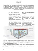
Of these, the Secure Digital (SD) format has emerged as the preeminent leader of the pack,
which includes the older MultiMediaCard (MMC) format on which SD is based. The SD
card is slightly thicker than the MMC and has a write-protect notch (and often a switch to
open and close the notch), unlike MMC. Figure 1.32 is a photo of an SD card with size ref-
erence. Officially, these devices are 32mm by 24mm.
FIGURE 1.32 A typical SD card
Even smaller devices, such as mobile phones, have an SD solution for them. One of these
products, known as miniSD, is slightly thinner than SD and measures 21.5mm by 20mm. The
other, microSD, is thinner yet and only 15mm by 11mm. Both of these reduced formats have
adapters allowing them to be used in standard SD slots.
Table 1.4 lists additional memory card formats.
TABLE 1.4 Additional Memory Card Formats
Format Dimensions Details Year Introduced
CompactFlash (CF) 36mm by 43mm Used by IBM for Microdrives;
Type I and Type II variants
1994
MiniCard 45mm by 37mm Defunct; promoted by Intel,
AMD, Fujitsu, Sharp
1995
4831x.book Page 43 Tuesday, September 12, 2006 11:59 AM
44
Chapter 1
Identifying Personal Computer Components
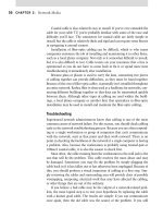
Figure 1.33 shows the memory card slots of an HP PhotoSmart 7550 printer, which is capable
of reading these devices and printing them directly or creating a drive letter for access to the con-
tents over its USB connection to the computer. Clockwise from upper left, these slots accommodate
CF/Microdrive, SmartMedia, Memory Stick (bottom right), and MMC/SD. Exclusive external
card readers and those that can be mounted in a computer’s drive bay are common items on the
market today. The industry also provides almost any adapter or converter to allow the various for-
mats to work together.
As a final thought on SD cards, SD slots are not for flash memory only. The more general
SDIO (SD Input/Output) specification, which is based on and compatible with the SD specifi-
cation, seeks to bring a high-speed, low-power interface to mobile devices, in the same vein as
USB for computers. Not that SDIO can’t be used with laptops, but it is intended more for PDAs
or mobile phones for connectivity to small devices, such as GPS receivers, wireless or wired net-
work adapters, modems, bar-code readers, wireless serial adapters, radio and television tuners,
and digital cameras. Even external storage devices, such as hard drives and CD/DVD-ROM
drives, could be attached to these smaller handheld devices.
FIGURE 1.33 Card slots in a printer
SmartMedia (SM) 45mm by 37mm From Toshiba; intended to
replace floppies; still sells well
1995
Memory Stick 50mm by 21.5mm From Sony; standard, pro,
duo, and micro formats
available
1998
TABLE 1.4 Additional Memory Card Formats (continued)
Format Dimensions Details Year Introduced
4831x.book Page 44 Tuesday, September 12, 2006 11:59 AM
Identifying Purposes and Characteristics of Storage Devices
45
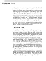
THUMB DRIVES
Also known as USB flash drives, thumb drives are incredibly versatile and convenient devices
that allow you to store large quantities of information in a very small form factor. Many such
devices are merely extensions of the host’s USB connector, extending out from the interface
but adding very little to its width, making them very easy to transport, whether in a pocket or
laptop bag. Figure 1.34 illustrates an example of one of these components and its relative size.
FIGURE 1.34 A USB thumb drive
Thumb drives capitalize on the versatility of the USB interface, taking advantage of the Plug
and Play feature and the physical connector strength. Upon insertion, these devices announce
themselves to Windows Explorer as removable drives and show up in the Explorer window
with a drive letter. This software interface allows for drag-and-drop copying and most of the
other standard Explorer functions performed on standard drives.
USB thumb drives have emerged as the de facto replacement for other removable storage
devices, such as floppies, edging out Zip and Jaz offerings from Iomega, as well as other pro-
prietary solutions.
USB-Attached External Disk Drives
Before USB, an external drive used a proprietary adapter and interface/cable combination or
the standard RS-232 serial or parallel port generally built into the computer. Since USB, there
seems to be no other way to do it. The fact is, there are other ways, but why muddy the water
with options when USB covers all the bases and is so ubiquitous in today’s systems?
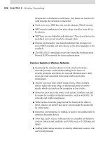
USB-attached external disk drives use the same drives that you might install in a drive bay
in your chassis; they simply employ a specialty chassis that houses only the drive and the sup-
porting circuitry that converts the drive interface to USB. Most often, the drive enclosure has
a DC power input and a Type-B USB interface, as shown in Figure 1.35. This external chassis
has its cover removed, and you can see the internal protective casing with the hard drive
mounted in it.
4831x.book Page 45 Tuesday, September 12, 2006 11:59 AM
46
Chapter 1
Identifying Personal Computer Components
FIGURE 1.35 External drive enclosure
Advanced Digital Storage
There are two technologies on the market today that seek to become the next standard in opti-
cal storage; each one offers backward compatibility to the lesser CD and DVD technologies.
One of these is known as High Density (or Definition) DVD (HD DVD). The other is known
as Blu-ray Disc (BD). Both technologies employ similar blue-violet laser and encoding tech-
niques, as well as disc size, with slightly differing results. The blue laser has a shorter wave-
length than the original red laser, which allows more data to be stored in the same space
because the laser can be focused more tightly to read data placed more closely.
However, depending on the reception blue-laser technologies receive in the public sector,
their times might come and go without much fanfare. Seemingly futuristic technologies, such
as perpendicular and holographic recording, might be here before the market realizes it needs
blue laser.
HD DVD
HD DVD can hold high-definition video or large quantities of data. HD DVD has a single-
layer capacity of 15GB. Dual-layer and triple-layer formats exist that hold two and three times
as much data, respectively. Publishers can include both standard DVD and HD DVD formats
on a single disc. This coexistence means that consumers, manufacturers, and retailers have
options during their transition to HD DVD, because the newer HD DVD discs can play in a
4831x.book Page 46 Tuesday, September 12, 2006 11:59 AM
Identifying Purposes and Characteristics of Power Supplies
47
standard DVD player. The incentive to upgrade remains, however, due to the higher definition
video awaiting owners on the same disc.
If the HD DVD format is applied to standard DVDs that do not use the blue laser, it can result
in capacities ranging from 5 to 18GB, offering a lower-cost alternative for those holding off on
upgrading to HD DVD. HD DVD uses a single lens in its optical mechanism, unlike Blu-ray tech-
nology. Therefore, both red and blue LED lasers can be incorporated into HD DVD drives that
are still more compact than those based on Blu-ray.
Blu-ray Disc
Although Blu-ray Disc uses a similar technology to that of HD DVD, it gets the laser closer to
the data and is able to store more data per layer, 25GB compared to HD DVD’s 15GB. Manu-
facturers led by Sony make players backward compatible with DVDs and capable of the same
high-definition video content. Initially, Blu-ray components were priced a bit higher than those
based on HD DVD, but Blu-ray was the first to hit the market with a consumer-recordable
version, including drives and media.
Identifying Purposes and Characteristics
of Power Supplies
The computer’s components would not be able to operate without power. The device in the
computer that provides this power is the power supply (Figure 1.36). A power supply converts
110 volt or 220 volt AC current into the DC voltages that a computer needs to operate. These
are +3.3 volts DC, +5 volts DC, –5 volts DC (ground), +12 volts DC, –12 volts DC (ground),
and +5 volts DC standby. The 3.3 volts DC and +5 volts DC standby voltages were first used
by ATX motherboards.
You might see volts DC abbreviated as VDC.
FIGURE 1.36 A power supply
4831x.book Page 47 Tuesday, September 12, 2006 11:59 AM
48
Chapter 1
Identifying Personal Computer Components
Power supplies contain transformers and capacitors that can discharge
lethal amounts of current even when disconnected from the wall outlet.
They are not meant to be serviced. Do not attempt to open them or do any
work on them.
Power supplies are rated in watts. A watt is a unit of power. The higher the number, the
more power the power supply (and thus your computer) can use. Most computers use power
supplies in the 250- to 500-watt range.
Classic power supplies used only three types of connectors to power the various devices
within the computer (Figure 1.37): floppy drive power connectors (Berg connectors), AT sys-
tem connectors (P8 and P9), and standard peripheral power connectors (Molex connectors).
Each has a different appearance and way of connecting to the device. In addition, each type
is used for a specific purpose. Newer systems have a variety of similar, replacement, and addi-
tional connectors.
Floppy Drive Power Connectors
Floppy drive power connectors are most commonly used to power floppy disk drives and
other small form factor devices. This type of connector is smaller and flatter (as shown in
Figure 1.38) than any of the other types of power connectors. These connectors are also called
Berg connectors. Notice that there are four wires going into this connector. These wires carry
the two voltages used by the motors and logic circuits: +5VDC (carried on the red wire) and
+12VDC (carried on the yellow wire); the two black wires are ground wires.
FIGURE 1.37 Standard power supply connectors
Floppy/Hard disk connectors
Berg connector
Molex connector
Motherboard connectors
Motherboard
Power supply
4831x.book Page 48 Tuesday, September 12, 2006 11:59 AM
Identifying Purposes and Characteristics of Power Supplies
49
AT System Connectors
The next type of power connector is called the AT system connector. There are two 6-wire
connectors, labeled P8 and P9 (as shown in Figure 1.39). They connect to an AT-style mother-
board and deliver the power that feeds the electronic components on it. These connectors have
small tabs on them that interlock with tabs on the motherboard’s receptacle. If there are two
connectors, you must install them in the correct fashion. To do this (on most systems), place
the connectors side by side with their black wires together, and then push the connectors onto
the receptacle on the motherboard.
Although it’s easy to remove this type of connector from the motherboard, the
tabs on the connector make it difficult to reinstall it. Here’s a hint: Place the con-
nector at a right angle to the motherboard’s connector, interlocking the tabs
in their correct positions. Then tilt the connector to the vertical position. The
connector will slide into place easily.
FIGURE 1.38 Floppy drive power connector
FIGURE 1.39 AT power supply system board connectors
4831x.book Page 49 Tuesday, September 12, 2006 11:59 AM
50
Chapter 1
Identifying Personal Computer Components
It is important to note that only computers with AT and baby AT motherboards use this
type of power connector.
Most computers today use some form of ATX power connector to provide
power to the motherboard.
Standard Peripheral Power Connector
The standard peripheral power connector is generally used to power different types of internal disk
drives. This type of connector is also called a Molex connector. Figure 1.40 shows an example of
a standard peripheral power connector. This power connector, though larger than the floppy drive
power connector, uses the same wiring color code scheme as the floppy drive connector.
Modern Power Connectors
Modern components have exceeded the capabilities of some of the original power supply connec-
tors. The Molex and Berg peripheral connectors remain, but the P8/P9 motherboard connectors
have been consolidated and additional connectors have sprung up.
FIGURE 1.40 A standard peripheral power connector
4831x.book Page 50 Tuesday, September 12, 2006 11:59 AM
Identifying Purposes and Characteristics of Power Supplies
51
ATX, ATX12V, and EPS12V Connectors
With ATX motherboards came a new, single connector from the power supply. PCI Express
has power requirements that even this connector could not satisfy. Additional 4- and 8-pin
connectors supply power to components of the motherboard, such as network interfaces,
specialty server components, and the CPU itself, that require a +12V supply in addition to the
+12V of the standard ATX connector. These additional connectors follow the ATX12V and
EPS12V standards. The ATX connector was further expanded by an additional four pins in
later specifications.
The ATX system connector (also known as the ATX motherboard power connector) feeds
an ATX motherboard. It provides the six voltages required, plus it delivers them all through
one connector: a single 20-pin connector. This connector is much easier to work with than the
dual connectors of the AT power supply. Figure 1.41 shows an example of an ATX system
connector.
When the Pentium 4 processor was introduced, motherboard and power supply manufacturers
needed to get more power to the system. The solution was the ATXV12 standard, which added
two supplemental connectors. One was a 6-pin auxiliary connector similar to the P8/P9 AT con-
nectors that supplied additional +3.3V and +5V leads and their grounds. The other was a 4-pin
square mini version of the ATX connector, referred to as a P4 connector, that supplied two +12V
leads and their grounds. EPS12V uses an 8-pin version, called the processor power connector, that
doubles the P4’s function with four +12V leads and four grounds. Figure 1.42 illustrates the P4
connector. The 8-pin processor power connector is similar but has two rows of four.
FIGURE 1.41 ATX power connector
4831x.book Page 51 Tuesday, September 12, 2006 11:59 AM
52
Chapter 1
Identifying Personal Computer Components
FIGURE 1.42 ATX12V P4 power connector
For servers and more advanced ATX motherboards that include PCIe slots, the 20-pin system
connector proved inadequate. This led to the ATX12V 2.0 standard and the even higher-end
EPS12V standard for servers. These specifications call for a 24-pin connector that adds addi-
tional positive voltage leads directly to the system connector. The 24-pin connector looks like a
larger version of the 20-pin connector. There are adapters available if you find yourself with the
wrong combination of motherboard and power supply. The 6-pin auxiliary connector disap-
peared with the ATX12V 2.0 specification and was never part of the EPS12V standard.
SATA Power Connectors
SATA drives arrived on the market with their own power requirements, in addition to their
new data interfaces. Refer back to Figure 1.14 and imagine a larger but similar connector for
power. You get the SATA power connector, shown in Figure 1.43. This connector is made up
of three each of +3.3V, +5V, and +12V leads, as well as five ground leads.
FIGURE 1.43 SATA power connector
4831x.book Page 52 Tuesday, September 12, 2006 11:59 AM