cwts certified wireless technology specialist official study guide exam pw0 070 phần 4 pps
Bạn đang xem bản rút gọn của tài liệu. Xem và tải ngay bản đầy đủ của tài liệu tại đây (932.18 KB, 50 trang )
Coverage and Capacity
107
wireless computer. This is an example of wide coverage. The applications in use on the wire-
less network will have an impact on the overall performance. If all 100 people are using
a CAD/CAM application, which is bandwidth intensive, the overall performance will be
poor because this type of application requires a lot of resources. Therefore more access
points, each covering less space, would parlay into better overall performance for the users.
Wide coverage in a densely populated area may allow too many users to connect to a single
access point, resulting in poor performance overall as explained with the CAD/CAM
application example. As mentioned earlier, wireless LANs use what is known as a shared
medium. In other words, all users connected to an access point will share the available band-
width. Too many users using powerful applications will overload the access point, adding
to the poor performance issues. This scenario can also be considered a capacity issue. In
this situation more access points with each AP covering a smaller area would be a better
solution.
Applications in Use
The application types in use—either software or hardware—can affect the bandwidth of an
access point. If the users connected to an access point use bandwidth-intensive applications
such as the CAD/CAM application mentioned earlier, this could result in poor throughput for
all users connected to that access point. This is another example where more access points,
with each covering a smaller area, could be a better solution than a single access point cover-
ing a large area. Multiple access points could allow the high-bandwidth users to be separated
from other parts of the network, increasing overall performance of the network.
Obstacles, Propagation, and Radio Frequency Range
Obstacles in an area, such as walls, doors, windows, and furnishings, as well as the physical
properties of these obstacles—thickness of the walls and doors, density of the windows, and
type of furnishings—can also affect coverage. The radio frequency used—either 2.4 GHz
or 5 GHz—will determine how well a signal will propagate and handle an obstacle. Parti-
tions, walls, and other obstacles will also determine the coverage pattern of an access point
because of the way RF behaves as it travels through the air. Behaviors of RF will be dis-
cussed later in this chapter in the section “Environment: RF Behavior.”
WLAN Hardware and Output Power
The wireless LAN hardware in use can also have an impact on the coverage area. Examples
include the antenna type, antenna orientation, and gain of the antenna. The higher the gain
of an antenna, the greater the coverage area; conversely, the lower the gain of an antenna, the
smaller the coverage area. The polarization of an antenna (horizontal vs. vertical) will also
have an effect on the coverage area because of the different shapes of the radiation patterns.
The output power of the transmitter or access point will also have an effect on coverage. The
higher the output power, the greater distance a signal will propagate. A higher power signal
will provide more coverage. Most enterprise-grade access points provide the capability to
control or adjust the output power.
38893c04.indd 107 5/18/09 5:01:21 PM
108
Chapter 4
N
Radio Frequency (RF) Fundamentals for Wireless LAN Technology
Capacity
One definition of capacity is the maximum amount that can be received or contained. An
example of this would be an elevator in a building. Typically an elevator will have a maxi-
mum number of people or amount of weight it can hold; this is usually stated on a panel
within the elevator. To ensure safety, the elevator may have a safety mechanism to prevent
overloading. Likewise, a restaurant has a certain number of chairs to hold customers;
therefore, they would have a maximum capacity of customers who can be served at any
one time. Does this mean that when a restaurant fills its seats to capacity, the doors close
and no other customers can enter the building? Not necessarily. In some cases, a restaurant
could have customers standing and waiting to be seated.
Just as an elevator or a restaurant has a limited number of people they can accommodate
comfortably, wireless access points also have a capacity. The capacity of an access point is
how many users the AP can service effectively, offering the best performance. This capacity
depends on several factors, including:
Software applications in use
ÛN
Desired throughput or performance
ÛN
Number of users
ÛN
The following sections discuss how these factors affect the capacity of an access
point.
What Happens When an Access Point Is Overloaded
If the capacity of a single access point has exceeded the maximum number of users or
devices based on the performance metrics, additional access points may need to be
added. If a wireless network is installed correctly, an access point will not be overloaded
with an excessive number of users. An overloaded access point will result in poor perfor-
mance and therefore unhappy users.
To understand why, look back at the restaurant example. If a restaurant seats 20 customers
and all 20 seats are taken, the restaurant has reached its capacity. Let’s say the restaurant
is short-staffed because two servers did not show up for work. The servers who did show
up will have to work extra hard to handle the customers. This may cause delays in service
because the servers need to handle more than their normal number of tables. The delays
may result in unhappy customers.
The same is true for wireless access points. If a wireless access point has reached its
capacity, it could get overloaded. This would result in its taking longer to handle any indi-
vidual request for access. The delays may result in unhappy users. Therefore this situation
could justify another access point in the area to handle the additional users. Just as a res-
taurant will not close its doors when all seats are taken, an access point will continue to
accept users to connect unless restrictions such as load balancing are implemented.
38893c04.indd 108 5/18/09 5:01:21 PM
Coverage and Capacity
109
Software Applications in Use
The software applications in use may affect the capacity of an access point. Some applica-
tions are more bandwidth-intensive than others. For example, word processing application
s
may not require much bandwidth whereas database or CAD/CAM applications may
require much more bandwidth than other applications. If high-bandwidth applications
are in use, the contention among the connected users will increase because they are using
a shared medium (air and RF). Therefore performance will potentially be reduced for all
users connected to the access point. The access point is providing the same amount of band-
width, but the overall performance has been decreased for the connected users because the
software applications are all using a lot of bandwidth.
Desired Throughput or Performance
The desired throughput or performance can also affect capacity. A large number of users
connected to an access point using a bandwidth-intensive application will cause poor per-
formance. Therefore, it may be necessary to limit the capacity to a certain number of users
to give the connected users the best performance possible. Any software application that is
bandwidth-intensive, such as CAD/CAM, streaming video, or file transfer protocol (FTP)
downloads, can have an effect on overall performance. One way to help resolve this would
be to use load balancing to limit the number of users that can connect to an access point.
Another way would be to add more access points.
Channel Reuse and Co-location
Earlier in this chapter, it was noted that the 2.4 GHz ISM band has a total of three non-
overlapping channels. In the U.S. FCC implementation of this band, the three non-overlapping
channels are 1, 6, and 11. This means there must be a separation of five channels in order
for them to be considered non-overlapping. In the 2.4 GHz ISM band, channels are sepa-
rated by 5 MHz. Taking this into consideration, channels must be separated by 25 MHz
in order to be considered non-overlapping. This is calculated from five channels of separa-
tion multiplied by 5 MHz (5
× 5 = 25). With deployments larger than a few access points,
a channel plan may be necessary. A channel plan will minimize the chance of interference
due to two transmitters set to the same or adjacent overlapping channels.
Figure 4.11 illustrates a 2.4 GHz deployment with no channel planning. Users in the
areas where the circles overlap will experience interference. This interference will result in
lower overall throughput for the connected users because of the spread spectrum technolo-
gies that wireless LANs use. This interference basically has the same effect as collisions
in an Ethernet network, resulting in retransmissions of data. A correct channel plan will
implement channel reuse and ensure overlapping cells will not use overlapping channels.
Channel reuse is using non-overlapping channels—for example 1, 6, and 11 in the 2.4 GHz
range—in such a way that the overlapping cells are on different RF channels. Figure 4.12
shows a 2.4 GHz deployment utilizing proper channel reuse. This channel reuse may be
accomplished by mapping out the access points on a floor plan and verifying that the RF
38893c04.indd 109 5/18/09 5:01:21 PM
110
Chapter 4
N
Radio Frequency (RF) Fundamentals for Wireless LAN Technology
cells propagated by the access points do not overlap on the same RF channels. This type of
channel plan can de done manually or with site survey software applications. Site survey
applications will be discussed in more detail in Chapter 9.
FIGURE 4.11 Users of these access points will experience overlapping channel
interference because they are all set to the same channel.
Channel 1 Channel 1 Channel 1
Channel 1 Channel 1 Channel 1
FIGURE 4.12 Co-location of access points with proper channel reuse. Overlapping
areas use different channels to prevent interference.
Channel 1 Channel 6 Channel 11
Channel 11 Channel 1 Channel 6
RF Range and Speed
How far and fast an RF signal can travel depends on a variety of factors, including line of
sight, interference, and the types of materials in the environment. This section discusses
these factors.
38893c04.indd 110 5/18/09 5:01:22 PM
RF Range and Speed
111
Line of Sight
RF communication between devices in 802.11 wireless networking requires a line of sight.
There are two types of line of sight to take into consideration: visual and RF.
Visual line of sight is the ability of the transmitter and receiver to see each other. In order
for wireless networking direct link communication to be successful there should be a clear,
unobstructed view between the transmitter and receiver. An unobstructed line of sight means
few or no obstacles blocking the RF signal between these devices.
Direct, RF line of sight is an unobstructed line between a radio transmitter and receiver.
This line will be surrounded by an area of radio frequency transmissions known as the
Fresnel zone.
The RF line of sight, or the radio transmissions between a transmitter and receiver,
could be affected if the total area of the Fresnel zone is blocked by more than 40 percent.
This blockage could be from a variety of sources such as trees, buildings, terrain, or other
obstacles, including the curvature of the earth. Figure 4.13 illustrates a Fresnel zone.
FIGURE 4.13 Oval area represents the Fresnel zone RF coverage area between a
transmitter and receiver.
One way to think about this line of sight is by way of an analogy of two people looking
at each other. If two people about the same height standing some distance apart are mak-
ing direct eye contact, they have a good visual line of sight. In addition to being able to see
directly in front of them, people also have peripheral vision. This peripheral vision gives
people the ability to see movement and objects outside of their direct line of sight or direct
eye contact. This peripheral vision or side vision is similar to the Fresnel zone theory.
EXERCISE 4.1
How to Demonstrate Fresnel Zone and Blockage
Here is one way to demonstrate Fresnel zone. Focus your eyes at a location on a wall.
Make sure there are obstacles or movement off to both left and right sides of your view.
Hold your hands down to your sides. Continue to focus your eyes for a minute or so then
take your right, left, or both hands and slowly raise them from your sides toward the side
of your head while blocking your peripheral vision. You’ll notice as your hands get closer
to the side of your head the view of the objects or movement to the sides will be blocked
by your hands. This is an example of a blocked Fresnel zone.
38893c04.indd 111 5/18/09 5:01:22 PM
112
Chapter 4
N
Radio Frequency (RF) Fundamentals for Wireless LAN Technology
Sixty percent of the total area of the Fresnel zone must be clear of
obstacles in order to have RF line of sight.
Interference
Interference from a radio frequency point of view occurs when a receiver hears two different
signals on the same or similar frequencies. Interference causes distortion. In wireless LANs,
this interference can have a severe impact on the quality of signal received by the wireless
device. This corrupted signal will decrease the amount of data the device can effectively receive,
thereby causing less data throughput. A wireless LAN receiver has similar characteristics to the
human ear. Both can hear a range of frequencies. If one person is speaking and a number of
people are listening to this speaker, this is similar to a single transmitter and multiple receiv-
ers. If a second person started to speak at the same time, people listening may not be able to
understand both speakers. In a sense they are experiencing interference.
As discussed earlier in this chapter, an IEEE 802.11 wireless network may use the unli-
censed 2.4 GHz industrial, scientific, and medical (ISM) band. This band is also used for
many other devices, including:
Cordless phones
ÛN
Microwave ovens
ÛN
Medical devices
ÛN
Industrial devices
ÛN
Baby monitors
ÛN
Other WLANs
ÛN
Because these devices also use radio frequency to operate, and the frequency is in the
same unlicensed band as IEEE 802.11 wireless networks, they have potential to interfere
with one another. Although they may coexist in the same RF space, the interference factor
needs to be taken into consideration. This can be done as part of the site survey process.
Co-channel and Adjacent Channel Interference
Co-channel or adjacent channel interference occurs when two devices in the same physical
area are tuned to a close or same radio frequency channel. For example, an access point
on channel 1 and another access point on channel 2 in close or hearing range of each other
will experience adjacent channel interference. Some of the symptoms of this type of inter-
ference are reduced throughput compared to what is normal, and the equivalent of colli-
sions causing data retransmissions.
38893c04.indd 112 5/18/09 5:01:22 PM
RF Range and Speed
113
Co-channel interference is defined as two different radio transmitters
using the same frequency. The IEEE 802.11-2007 standard, however, defines
interference between channels 1 and 2 as co-channel interference caused
by overlapping channels. According to the standard, adjacent channel
interference for HR/DSSS and ERP in the 2.4 GHz ISM band is caused by
frequencies greater than or equal to 25 MHz separation, such as channels
1 and 6. The terms co-channel and adjacent are used loosely in the wire-
less LAN industry. Please consult specific manufacturer’s documentation
for their definition. The CWNP program complies with the IEEE standards
definition.
Overlapping interference is defined as two devices (such as access points) on the same
frequency overlapping one another. For example, two access points in close proximity to
each other, one on channel 1 and the other on channel 3, might interfere with each other.
Both adjacent channel interference and co-channel channel interference will cause poor
throughput on a wireless network. In a wireless network, co-channel or adjacent channel
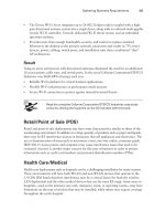
interference can have the same impact. Figure 4.14 shows that 2.4 GHz ISM band channel 4
and channel 6 overlap.
FIGURE 4.14 Channel overlap in the 2.4 GHz ISM band
1611
Access point
on channel 6
Access point
on channel 4
Channel
overlap
Representation of 2.4 GHz ISM band, consisting
of 14 channels. Channels 1, 6, and 11 are labeled.
A properly designed wireless LAN will have overlapping RF cells. Overlapping cells
provide continuous coverage for the entire area where the access points are placed. Overlap-
ping cells allow devices to move from one access point to another and maintain a connec-
tion. A well-designed wireless LAN will also minimize or eliminate overlapping channel
interference. This design includes assigning non-overlapping RF channels to cells that do
overlap with each other. The frequency in use is determined by how many non-overlapping
channels are available in the band. For example, in the United States, the 2.4 GHz band used
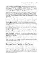
for 802.11b/g/n has three non-overlapping channels—1, 6, and 11. Figure 4.15 shows 2.4 GHz
ISM band with three non-overlapping channels, channels 1, 6, and 11.
38893c04.indd 113 5/18/09 5:01:23 PM
114
Chapter 4
N
Radio Frequency (RF) Fundamentals for Wireless LAN Technology
FIGURE 4.15 Five channels of separation and 25 MHz of separation between
non-overlapping channels
1611
Access point
on channel 6
2.437 MHz
Access point
on channel 1
2.412 MHz
Access point
on channel 11
2.462 MHz
Representation of 2.4 GHz ISM band, consisting of
14 channels. Channels 1, 6, and 11 are non-overlapping.
WLAN/WPAN Interference
The performance of IEEE 802.11 wireless networks can be affected when they are co-
located with IEEE 802.15 wireless personal area networks or WPANs. Bluetooth is an
example of a personal area network. Like 802.11, Bluetooth devices operate in the 2.4 GHz
frequency range and use frequency hopping spread spectrum (FHSS). This functionality
could interfere with IEEE 802.11 wireless networks. Newer versions of Bluetooth that use
adaptive frequency hopping (AFH) have less of a chance of interfering with other wireless
networks. Adaptive frequency hopping allows devices such as Bluetooth to adapt to the RF
environment by seeking areas of interference and not operating in those specific frequency
ranges.
Bright Sunlight Interference
The IEEE 802.11 standard does address infrared (IR) communications. IR uses near visible
light at a very high band on the radio spectrum to communicate. Since the CWTS exam
only explores RF used in the ISM and UNII bands, IR will not be discussed in this book.
Bright sunlight will not affect wireless LAN communications that use the 2.4 GHz ISM
and 5 GHz UNII bands; however, it could have an impact on infrared communications.
Environment: RF Behavior
In addition to various types of RF interference, the interaction between RF and the sur-
rounding environment can also affect the performance of IEEE 802.11 wireless networks.
RF behavior is the result of environmental conditions including:
Reflection
ÛN
Refraction
ÛN
Diffraction
ÛN
38893c04.indd 114 5/18/09 5:01:23 PM
RF Range and Speed
115
Scattering
ÛN
Absorption
ÛN
Diffusion
ÛN
Reflection
Reflection occurs when an RF signal bounces off a smooth, nonabsorptive surface such as
a table top and changes direction. Reflections can affect indoor wireless LAN installations
fairly significantly in certain cases. Depending on the interior of the building—such as the
type of walls, floors, or furnishings—there could be a large number of reflected signals. If
not properly handled, reflections could cause a decrease in throughput and poor network
performance. Figure 4.16 illustrates reflection.
FIGURE 4.16 RF reflection
Incoming RF Reflected RF
Smooth surface such as table top
Think of a ping-pong game when it comes to reflection. When a ping-pong
ball is served or hit, it comes in contact with the table—a smooth, hard
surface—and bounces off in a different direction. This is similar to how
reflection works with radio frequency.
Refraction
When an RF signal passes between mediums of different densities, it may change speeds
and also bend. This behavior of RF is called refraction. Glass is an example of material that
may cause refraction. When an RF signal comes in contact with an obstacle such as glass,
the signal is refracted (bent) as it passes through and some of the signal is lost. The amount
of loss depends on the type of glass, thickness, and other properties. Figure 4.17 shows
refraction.
38893c04.indd 115 5/18/09 5:01:23 PM
116
Chapter 4
N
Radio Frequency (RF) Fundamentals for Wireless LAN Technology
FIGURE 4.17 RF refraction
Incoming RF
Refracted RF
Glass surface
Diffraction
When an RF signal passes an obstacle, the wave changes direction by bending around the
obstacle. This RF behavior is called diffraction. A building or other tall structure could
cause diffraction, as could a column in a large open area or conference hall. Figure 4.18
illustrates diffraction. When the signal bends around a column, building, or other obstacle,
the signal weakens, resulting in some level of loss.
FIGURE 4.18 RF diffraction
Incoming RF
Diffracted RF
Diffracted RF
Building rooftop
Demonstrating Diffraction: Rock in a Pond
You can demonstrate diffraction by using a pond of still water. Place a large object such
as a two-by-four piece of lumber in a pond of still water. After the water settles, try to drop
a pebble or small rock off to the side of the piece of lumber. Watch closely and you will see
the ripple of the water diffract around the lumber.
38893c04.indd 116 5/18/09 5:01:24 PM
RF Range and Speed
117
Scattering
When an RF signal strikes an uneven surface, wavefronts of the signal will reflect off the
uneven surface in several directions. This is known as scattering. Figure 4.19 illustrates
scattering. Scattering is another form of loss that may severely degrade the RF signal.
Absorption
When material absorbs an RF signal, no signal penetrates through the material. An exam-
ple of absorption is the human body. The human body has a high water content and will
absorb RF signals. This type of absorption can be a problem for wireless network deploy-
ments in certain environments. Densely populated areas such as airports and conference
halls need to consider absorption when designing a wireless LAN deployment. Figure 4.20
shows absorption.
FIGURE 4.19 RF scattering
Incoming RF
Scattered RF
Uneven surface
FIGURE 4.20 RF absorption
Incoming RF
Absorbing material
Diffusion
Diffusion occurs when the RF signal naturally widens as it leaves an antenna element. This is
known as free space path loss (FSPL). FSPL is the greatest form of loss factor in an RF link. FSPL
is calculated using frequency and distance as variables. The receiving antenna is only able to
receive a small amount of the transmitted signal because of this widening effect of the diffused
signal as it propagates through the air. Any signal that is not received is considered loss.
38893c04.indd 117 5/18/09 5:01:25 PM
118
Chapter 4
N
Radio Frequency (RF) Fundamentals for Wireless LAN Technology
Basic Units of RF Measurement
If a person were given a dollar bill, they would be one dollar richer. If this person were given
100 cents, they would still be one dollar richer. From this example, we see 1 dollar = 100 cents
and 1 cent = 1/100th of a dollar. One dollar and 100 cents are the same net amount, but a
cent and a dollar are different units of currency.
The same is true for radio frequency measures of power. The basic unit of measure for
radio frequency is the watt. A wireless access point may be set to an output of 30 mW
(milliwatts) of power. A milliwatt is 1/1000 of a watt. Just as in currency cents and dollars
are both denominations of money, watts and milliwatts are measurements of RF power.
Other units of measurement for RF are dB, dBi, dBd, and dBm.
Absolute Measurements of Power
The amount of power leaving a wireless access point is one example of an absolute measure
of power. This is an actual power measurement and not a ratio or a relative value. A typical
amount of output power from an access point is 100 mW.
The measure of AC power can be calculated using a very basic formula. The formula is:
P = E * I
Power (P) equals voltage (E) multiplied by current (I).
A simple example would be to calculate the power from 1 volt and 1 amp. Using the
given variables, the formula is:
P = 1 volt * 1 amp
The answer would be power = 1 watt.
The formula P = E * I is for reference only to demonstrate calculation of
power. You will not need to know this formula for the CWTS exam.
Watt (W)
The watt is a basic unit of power measurement. This is an absolute value or measurable
value. Most wireless networks function in the milliwatt range. Power level in watts is a
common measurement in long distance point-to-point and point-to-multipoint applications.
Milliwatt (mW)
One milliwatt is 1/1000 of a watt. This is a common value used in RF work and IEEE
802.11 wireless LANs. The output power of an access point typically ranges from 1 mW to
38893c04.indd 118 5/18/09 5:01:25 PM
Basic Units of RF Measurement
119
100 mW. Most enterprise-grade access points allow you to change the output power. Most
SOHO-grade access points have a fixed output power, typically 30 mW. The milliwatt is
also an absolute unit of power measurement.
Decibel Relative to a Milliwatt (dBm)
dBm is the power level compared to 1 milliwatt. This is based on a logarithmic function.
A good rule to remember is 0 dBm = 1 mW. This value is considered as absolute zero. Using a
formula or basic RF calculation rules, one can easily convert any milliwatt value to decibels.
For example 100 mW = 20 dBm. The dBm is also an absolute unit of power measurement.
A dB is an example of a change in power or relative measurement of power where dBm is
measured power referenced to 1 milliwatt or an absolute measure of power. The next sec-
tion discusses relative measurements of power.
Remember, absolute values are measurable values of power such as watt,
milliwatt, and decibel milliwatt.
Relative Measurements of Power
Changes in RF power are known as relative. dB and dBi are relative measurements of
power. An example would be an RF amplifier. If the input power to an amplifier is 10 mW
and the output power is 100 mW, the gain of the amplifier is 10 dB—a change in power.
If the input power to an antenna is 100 mW and the output power is 200 mW, the gain
of the antenna is 3 dBi—a change in power. Both of these are examples of changes in
power and are known as relative.
Decibel (dB)
The decibel (dB) is a ratio of two different power levels caused by a change in power. Fig-
ure 4.21 shows how an amplifier will provide an increase or change in power.
FIGURE 4.21 Output doubled in power from 100 mW to 200 mW from amplifier with a
gain or change in power of +3 dB
Amplifier
+3dB
100mW
Input Output
200mW
38893c04.indd 119 5/18/09 5:01:26 PM
120
Chapter 4
N
Radio Frequency (RF) Fundamentals for Wireless LAN Technology
Basic RF Math: The 3s and 10s Rule
This section is beyond the scope of the CWTS exam objectives and is for informational
purposes only.
There is a simple way to perform any RF math calculation without having to use loga-
rithms and mathematical formulas. This method is known as the 3s and 10s Rule (or
sometimes the 10s and 3s Rule). If you remember five basic steps you can perform any RF
math calculation. The five basic steps are as follows:
0 dBm = 1 mW (starting point)
ÛN
Increase by 3 dBm and power in mW doubles or
ÛN
× 2
Decrease by 3 dBm and power in mW is cut in half or ÷ 2
ÛN
Increase by 10 dBm and power in mW is multiplied by 10 or
ÛN
× 10
Decrease by 10 dBm and power in mW is divided by 10 or ÷ 10
ÛN
Decibel Isotropic (dBi)
Decibel isotropic (dBi) is the unit that represents the gain or increase in signal strength
of an antenna. The term isotropic in the RF world means energy broadcast equally in all
directions in a spherical fashion. An imaginary, perfect antenna is known as an isotropic
radiator. This is a theoretical concept and is used in reference and calculations. dBi will be
discussed and used in more detail in Chapter 6. Table 4.4 shows a summary of absolute and
relative power measurements.
TABLE 4.4 Absolute and Relative Measures of Power
Absolute Power Relative Power
Watt dB
Milliwatt dBi
dBm dBd
Remember, relative values are changes in power from one value to another
value. dB, dBi, and dBd measure relative power.
38893c04.indd 120 5/18/09 5:01:26 PM
Basic Units of RF Measurement
121
Decibel Dipole (dBd)
The gain of some antennas may be measured in decibel dipole (dBd). This unit of measure-
ment refers to the antenna gain with respect to a reference dipole antenna. The gain of most
antennas used in wireless LANs is measured in decibel isotropic (dBi); however some manu-
facturers may reference gain in dBd. The following simple formula derives the dBi value
from the dBd value:
dBi = dBd + 2.14
This formula converts from dBi to dBd:
dBd = dBi – 2.14
dBd vs. dBi
You are a procurement agent working for a manufacturing company. An engineer orders
some antennas to be used in a wireless LAN deployment. The part number you received
from the engineer on the bill of materials is for antennas that are currently out of stock at
your normal supplier. The order has to be placed as soon as possible, but technical sup-
port for the vendor is gone for the day and you are not able to get any assistance.
You found what appears to be a reasonable alternate for the requested antennas. How-
ever, the gain of the antennas does not exactly match what the engineer documented on
the bill of materials. The engineer requested omnidirectional antennas with a gain of 6
dBi. You found what appears to be a comparable alternate with a gain of 6 dBd. It will be
necessary for you to determine if these antennas will work. Not quite understanding the
difference, you do some research to determine the difference between dBd and dBi. After
searching various websites you find a formula to convert the two different units:
dBi = dBd + 2.14
Using your calculator, you enter the value from the specification sheet for the alternate
antennas:
6 dBd + 2.14 = 8.14 dBi
Unfortunately, the antennas found will not be a good alternate in this example. Back to
the drawing board!
38893c04.indd 121 5/18/09 5:01:26 PM
122
Chapter 4
N
Radio Frequency (RF) Fundamentals for Wireless LAN Technology
Summary
This chapter looked at radio frequency basics and the essential role RF plays in the world
of IEEE 802.11 wireless LANs. You learned the definition and understanding of RF as it
pertains to wireless networking and the basic characteristics or properties of RF such as
wavelength, frequency, amplitude, and phase. This chapter described devices such as trans-
mitters and receivers and how they communicate. In wireless LAN technology, an example
of a transmitter and receiver is an access point and client device. This chapter also discussed
the unlicensed RF bands and channels used in the 2.4 GHz ISM and 5 GHz UNII ranges
for wireless LAN communications. Coverage and capacity are two important areas that
should be closely looked at in order to ensure a wireless deployment will offer reliable con-
nectivity and perform well for the user base. This chapter also looked at correct channel
reuse to minimize interference from co-location of access points. This chapter explored cause
and effect of co-channel interference from sources other than wireless networks operating
in the ISM and UNII bands. We also looked at RF behaviors such as reflection, refraction,
and absorption, and the impact of propagation on radio waves. Finally, we discussed RF
units of measure, including watt, milliwatt, dB, and dBi.
Exam Essentials
Know the basic characteristics or properties of radio frequency. Understand the charac-
teristics of radio frequency such as wavelength, phase, frequency, and amplitude.
Be familiar with the frequencies used for wireless networks. Know the unlicensed ISM
and UNII bands available for use with wireless networks.
Understand wireless network coverage and capacity. Know the difference between cover-
age and capacity and the factors that will have an impact on both.
Know what RF factors will affect the range and speed of wireless networks. Understand
the effects of interference and the devices that cause interference. Be familiar with the envi-
ronmental conditions that cause reflection, refraction, diffraction, scattering, and absorp-
tion. Understand their impact on the propagation of RF signals.
Identify basic RF units of measurement. Understand the difference between absolute and
relative measures of RF power. Define W, mW, dB, dBm, and dBi.
38893c04.indd 122 5/18/09 5:01:26 PM
Key Terms
123
Key Terms
absolute measure of power
absorption
diffraction
gain
isotropic radiator
reflection
refraction
RF line of sight
scattering
visual line of sight
38893c04.indd 123 5/18/09 5:01:26 PM
124
Chapter 4
N
Radio Frequency (RF) Fundamentals for Wireless LAN Technology
Review Questions
1. What is the term defining the amount of times a cycle of an RF signal will oscillate in one
second?
A. Phase
B. Frequency
C. Amplitude
D. Wavelength
2. How many non-overlapping channels are available in the unlicensed 2.4 GHz ISM band?
A. 1
B. 3
C. 6
D. 11
3. The capacity of an access point is dependent upon which factors? (Choose two.)
A. Number of users
B. Channel reuse
C. Co-location
D. Software applications
E. Frequency
4. When an RF signal passes between mediums of different densities and may change speeds
and bend, the behavior is:
A. Refraction
B. Reflection
C. Scattering
D. Diffraction
5. What two devices use RF to communicate? (Choose two.)
A. Transmitter
B. Transistor
C. Reactor
D. Reflector
E. Receiver
38893c04.indd 124 5/18/09 5:01:26 PM
Review Questions
125
6. Which are relative measures of RF power? (Choose two.)
A. mW
B. dB
C. dBm
D. dBi
E. Watt
7. In the 2.4 GHz range, what distance between the center frequencies (in megahertz) is
required for two channels to be considered non-overlapping for HR/DSSS?
A. 5 MHz
B. 22 MHz
C. 25 MHz
D. 30 MHz
8. Two characteristics of RF signals are:
A. Amplitude
B. Reflection
C. Phase
D. Refraction
E. Diffraction
9. How many channels are available for wireless LANs to use in the unlicensed UNII-1 band?
A. 2
B. 4
C. 6
D. 11
10. Which are absolute measures of RF power? (Choose two.)
A. Watt
B. dB
C. mW
D. dBi
E. dBd
11. Which two channels are considered non-overlapping in the 2.4 GHz band?
A. 1 and 6
B. 2 and 6
C. 6 and 10
D. 11 and 13
38893c04.indd 125 5/18/09 5:01:26 PM
126
Chapter 4
N
Radio Frequency (RF) Fundamentals for Wireless LAN Technology
12. How many channels are available for wireless LAN use in the unlicensed 2.4 GHz ISM band?
A. 8
B. 10
C. 11
D. 14
13. The range of a 2.4 GHz signal is mostly dependent on which RF characteristic?
A. Frequency
B. Wavelength
C. Amplitude
D. Phase
14. Which item has an effect on RF line of sight?
A. Phase
B. Obstacles
C. Interference
D. Amplitude
15. How many channels are available for wireless LAN use in the unlicensed middle
UNII-2e band?
A. 4
B. 6
C. 11
D. 14
16. The amplitude of an RF signal is:
A. Height
B. Length
C. Shift
D. Width
17. An 802.11b channel is how wide in MHz?
A. 5 MHz
B. 22 MHz
C. 25 MHz
D. 30 MHz
38893c04.indd 126 5/18/09 5:01:26 PM
Review Questions
127
18. When an RF signal bounces off a smooth non-absorptive surface, the behavior is:
A. Refraction
B. Reflection
C. Scattering
D. Diffraction
19. What is the gain of an antenna measured in?
A. dB
B. dBc
C. dBi
D. dBm
20. When RF passes or bends around an obstacle such as a building or column, the behavior is:
A. Reflection
B. Refraction
C. Scattering
D. Diffraction
38893c04.indd 127 5/18/09 5:01:26 PM
128
Chapter 4
N
Radio Frequency (RF) Fundamentals for Wireless LAN Technology
Answers to Review Questions
1. B. Frequency is the number of times in one second a signal will oscillate. Phase is a shift,
amplitude is height, and wavelength is a distance of one cycle.
2. B. There are three non-overlapping channels in the 2.4 GHz ISM band. Fourteen channels
are available in this band. The locale will determine which channels can be used.
3. A, D. The capacity of an access point is dependent upon the number of users and software
applications in use. Too many users or too many bandwidth-intensive applications will
affect the performance of an access point.
4. A. Refraction is when a signal will change speeds and bend when passing between medi-
ums of different densities. Reflection bounces off a smooth surface, diffraction will pass
around, and scattering bounces off an uneven surface.
5. A, E. RF communications require a transmitter and receiver. A transistor is an electronic
component; a reactor does not exist in RF.
6. B, D. dB and dBi are relative measures of RF power. mW, dBm, and watt are absolute mea-
sures of RF power.
7. C. 25 MHz is required for channels to be considered non-overlapping. 22 MHz is the
width of a DSSS channel in the 2.4 GHz band.
8. A, C. Amplitude and phase are two characteristics of RF signals. Reflection, refraction,
and diffraction are behaviors of RF.
9. B. UNII -1 band has four channels available for wireless LAN use. Eleven channels are
available in UNII-2e.
10. A, C. Watt and mW are absolute measures of RF power. dB, dBi, and dBd are relative
measures.
11. A. Channels 1 and 6 are non-overlapping. There must be a separation of five channels (with
the exception of channel 14) to be considered non-overlapping in the 2.4 GHz band.
12. D. There are 14 channels available in the unlicensed 2.4 GHz ISM band. The channels used
are determined by the locale.
13. B. The wavelength is the distance of an RF signal. Frequency is how many times it oscil-
lates per second, amplitude is the height, and phase is a shift.
14. B. Obstacles affect the RF line of sight. Phase and amplitude are characteristics of radio
frequency, and interference affects the throughput.
15. C. There are 11 channels available for wireless LAN use in the unlicensed UNII-2e band.
The other three 5 GHz bands have only 4 channels each.
38893c04.indd 128 5/18/09 5:01:26 PM
Answers to Review Questions
129
16. A. The amplitude is the height of an RF signal. The length of one cycle is the wavelength,
the shift is phase, and width is not a valid factor.
17. B. A 2.4 GHz 802.11b signal is 22 MHz wide. 25 MHz is the distance required to be con-
sidered non-overlapping.
18. B. An RF signal that bounces off a smooth surface is reflection. Refraction passes through,
diffraction bends around, and scattering bounces off a non-smooth surface.
19. C. The gain of an antenna is measured in dBi. This is a relative measure of power.
20. D. Diffraction passes or bends around an obstacle. Reflection bounces off a smooth sur-
face, refraction passes through, and scattering bounces off an uneven surface.
38893c04.indd 129 5/18/09 5:01:26 PM
38893c04.indd 130 5/18/09 5:01:26 PM
Chapter
5
Access Methods,
Architectures, and
Spread Spectrum
Technology
THE FOLLOWING CWTS EXAM OBJECTIVES
ARE COVERED IN THIS CHAPTER:
Define concepts which make up the functionality of RF
and spread spectrum technology
OFDM & HR/DSSS channels
Co-location of HR/DSSS and OFDM systems
Adjacent-channel and co-channel interference
WLAN / WPAN co-existence
CSMA/CA operation – half duplex
Define and differentiate between the following physical
layer wireless technologies
HR/DSSS
OFDM
MIMO
38893c05.indd 131 5/19/09 6:04:56 AM