High Temperature Strain of Metals and Alloys Part 9 potx
Bạn đang xem bản rút gọn của tài liệu. Xem và tải ngay bản đầy đủ của tài liệu tại đây (401.9 KB, 15 trang )
118 7 Single Crystals of Superalloys
amount of primary creep, 10 to 20%, is exhibited. The extent of the primary
creep is found to vary with temperature and deviation of the orientation from
the < 001 > direction. A long steady-state stage is typical. This constitutes a
considerable proportion of the available rupture life of the material.
The research group from the University of Cambridge and Rolls-Royce
University Technology Center have been carried out investigations on the
problem of deformation of the single-crystal superalloys in detail [37, 38, 41,
42] using the CMSX-4 superalloy (see the chemical composition in Table S1,
Supplement 3).
The obtained creep data for CMSX-4 superalloy are shown in Fig. 7.5 [41].
The orientations of the tested single crystals were found to lie within 10
◦
of
the < 001 > direction. The test results are plotted in two forms: strain versus
time (A) and strain rate versus strain (B).
At 1023K (750
◦
C) the usual creep curve (with primary, steady-state and ter-
tiary stages)is observed [Fig.7.5(a)].At1223K(950
◦
C) the tertiary deformation
begins almost at once [Fig. 7.5(b)]. One can see in the inset of Fig. 7.5(b) that,
to a good approximation, the creep strain rate can be taken to be proportional
to the accumulated creep strain. At higher temperature 1423K (1150
◦
C) (and
under a lower stress) a small amount of strain is accumulated but there exists
a plateau where the creep strain is almost constant in time. Later the creep
strain dramatically increases with rupture eventually occurring [the typical
curve is Fig. 7.5(c)].
The dependence of the creep on the orientation of the CMSX-4 single crys-
tals is shown in Fig. 7.6 [42]. The orientations of the specimens after the creep
tests are plotted in the standard stereographic triangle in Fig. 7.7.
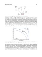
Fig. 7.6 Creep curves from CMSX-4 superalloy single crystals
tested at temperature 1023K and stress 750 MPa. The test
temperature belongs to the lower temperature interval.
Orientations of specimens are shown in Fig. 7.7. Reprinted
from Ref. [42] with permission from Elsevier Science Ltd.
7.2 Deformation at Lower Temperatures 119
Fig. 7.7 The orientation of the CMSX-4superalloyspecimens
within the stereographic triangle.
The effect of misorientation on the behavior of specimens at lower temper-
atures is very strong. The authors noted that the magnitude of the steady-state
creep rate correlates with the maximum rate in the primary creep stage. The
further from the < 001 > orientation the less the minimum creep rate (spe-
cimens M, N, Fig. 7.6, 7.7).
Primary creep at 1023K is due to a deformation on the {111} < 112 > slip
system. After some deformation and a lattice rotation the strain is associated
with at least two slip systems of type {111} < 112 >.
The influence of stress on strain is of interest. When the stress is large
enough to promote primary creep, then the creep strain evolution is relatively
insensitive to its value (Fig. 7.8). The “threshold” stress for primary creep at
1023K appears to lie between 600 and 750 MPa.
A physical mechanism of strain at a given temperature is supposed to be
the cause of the observed creep behavior. This is confirmed by transmission
electron microscopy.
The γ/γ
structure of the cast single crystal may be considered as two inter-
dependent systems. Therefore the properties of phases influence the genera-
tion and motion of dislocations as do the phase boundaries. In the conditions
under consideration the γ phase, being a soft constituent, is the source that
generates deforming dislocations. The precipitates are permitted to deform
only elastically, while the matrix can be deformed both elastically and plasti-
cally. The slip in the γ phase occurs on octahedral planes, {111} < 110 >. The
matrix dislocations have Burgers vectors of the type a/2 < 110 > in a plane
of this type. The a/2 < 110 > dislocations spread through the γ channels
between the dendrites of the cast structure.
120 7 Single Crystals of Superalloys
Fig. 7.8 The creep curves from CMSX-4 superalloy single
crystals tested at 1023K at various stress levels for specimens
oriented within 10
◦
of < 100 >. Reprinted from [42] with
the permission from Elsevier Science Ltd.
During the incubation period of creep the dislocations propagate from
each dislocation grow-in source. The local density of grow-in dislocations was
estimated to be about 10
11
m
−2
in CMSX-3 superalloy tested at 1098K [43].
The deforming dislocations have most probably the same Burgers vectors for
an orientation with the highest resolved shear stress.
During creep deformation the ordered structure of the γ
phase requires
that two dislocations in the γ phase must combine to be able to enter the
γ
phase as a superdislocation (Fig. 6.18). The associated energy of the anti-
phase boundary is a high barrier to the entry of dislocations, so the γ
phase
remains largely undeformed during the majority of the specimen rupture life
under low and moderate stresses.
In CMSX-4 superalloy tested at 1023K the ribbons of net Burgers vector
a/6 < 112 > are the most striking feature of the structure of crept speci-
mens. The term “ribbon” is used to describe the observed configuration of
overall Burgers vector a<112 > separated by superlattice stacking faults and
anti-phase boundary faults [38]. The authors note that large numbers of a/2
< 110 > dislocations are present in the structure of tested specimens. The
dislocations expand in the γ channels when creep deformation proceeds. The
two dislocations a/6 < 112 > are separated as the partials pass through the γ
phase. Where the ribbon of two partial dislocations passes the γ
phase they
are constricted by the anti-phase boundary energy.
As the primary creep deformation proceeds, the creep rate drops since
secondary slip systems become activated. The lattice rotation which occurs is
considered to be a superposition of the deformation associated with two or
more {111} < 112 > slip systems.
7.2 Deformation at Lower Temperatures 121
The authors [38] describe the physical mechanism of the primary creep of
the < 001 > oriented single crystals as follows.
“The first step”: two dislocations, both slipping in the γ phase on the (111)
plane, combine to produce the leading half of the a<112 > ribbon:
a/2[10
¯
1] + a/2[01
¯
1] → a/2[11
¯
2]
“The second step” consists in the dissociation:
a/2[11
¯
2] → a/3[11
¯
2] + a/6[11
¯
2]
The leading a/3[11
¯
2] dislocation is able to penetrate into the γ
-particle,
shearing it to leave a superlattice intrinsic stacking fault bounded by the
a/6[11
¯
2] partial which remains at the γ/γ
boundary. The trailing dislocation
cannot enter the γ
phase without forming an anti-phase boundary. Entry
would increase the energy on the deforming plane. In order to form the full
a[11
¯
2] dislocation, which is able to pass through the γ
phase and to restore the
unfaulted structure, presumably two further dislocations of the same Burgers
vectors are necessary:
a/2[10
¯
1] + a/2[01
¯
1] + a/2[10
¯
1] + a/2[01
¯
1] →
→ a/3[11
¯
2] + a/6[11
¯
2] + a/3[11
¯
2] + a/6[11
¯
2]
In Fig. 7.9 one can see the early stages of the ribbon nucleation that have
been proposed by Rae et al. [38]. Two dislocation loops of Burgers vectors
a/2[10
¯
1] and a/2[01
¯
1] have moved in the γ phase on the same (111) plane [see
the right lower corner of scheme (b)]. They have combined to form a leading
a/3[11
¯
2] dislocation. This slips through γ
particles leaving a small circle of
the superlattice intrinsic stacking fault surrounded by the trailing a/6[11
¯
2]
dislocation lying at the γ/γ
boundary. To complete the ribbons two further
dislocations of the same Burgers vector would be needed to thread their way
into the narrowchannel of the γ phase. Oncenucleated the dislocation ribbons
move until they are halted by interaction with other dislocations. The ribbon
velocity has been estimated to be of the order of 1.2 nm s
−1
. This corresponds
to a ribbon crossing one γ
particle every 340 s.
The primary creep is related to a rise in the population of a/2 < 110 >
dislocations. A primary creep strain of the order of 5% can be achieved by
the movement of ribbons. Dislocations accumulating at the γ/γ
interfaces
provided effective pinning for the mobile dislocation ribbons and play a role
122 7 Single Crystals of Superalloys
Fig. 7.9 The first stage of the nucleation
of a dislocation ribbon. The CMSX-4
single-crystal superalloy tested at 1023K.
(a) Electron micrograph. (b) Diagram
identifying the dislocations in (a). The
area of the superlattice intrinsic stacking
fault (SISF) is shaded. Reprinted from [38]
with permission from Elsevier Science
Ltd.
in terminating the primary creep. Thus, the primary creep at lower tempera-
tures starts with the propagation of a/2 < 110 > dislocations through the γ
channels. The sources of these dislocations supposedly are grow-in disloca-
tions that are located between the dendrites. A primary creep can also occur
when a population of a/2 < 112 > dislocations has become established and
if the shear stress is sufficiently high.
The addition of rhenium and ruthenium and the ageing heat treatment
have an important effect on the properties of a new generation of single-
crystal superalloys. Experiments have revealed that as the alloys have become
more creep resistant, the propensity for primary creep has increased.
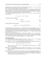
Two different types of creep behavior have been observed at 1033K under
a stress of 840MPa with the superalloys denoted as MC544, CMSX-10M and
MC544 (Fig. 7.10) [34]. The first is characterized by a high amount of primary
creep (3–10%). As a result the rupture life is reduced. The primary creep stage
is preceded by an incubation period and is followed by a distinct secondary
creep stage. The minimum creep rate increases with the primary creep strain.
The tertiary stage is short. If the primary stage is limited (0.25 %, MC534
superalloy) then a continued steady state creep leads to relatively long rupture
life of the specimen.
The increase in the size of the γ
particles promotes glide of a/2 < 110 >
dislocations within the γ matrix and leads to a decrease in the primary creep
amplitude. However, the excessive increase in the size of the γ
particles
7.2 Deformation at Lower Temperatures 123
Fig. 7.10 The results of tests on various single-crystal
superalloys at 1033K and stress 840MPa. Nominal chemical
compositions are listed in Table S1. (a) Entire creep curves,
(b) enlarged view of the primary creep stage. Reprinted from
Ref. [34] with permission from Elsevier Science Ltd.
facilitates the deformation by Orowan bypassing and reduction of the rupture
life.
The various structure factors are likely to affect the physical mechanism of
strain of the investigated superalloys. There exists a competition between the
Orowan mechanism of bowing of the dislocations between the γ
particles
and the cutting of particles by partial dislocations. The difficulty for matrix
dislocations in moving between γ
precipitates by {111} < 110 > slip results
in the short incubation period. It is energetically more favorable for γ disloca-
tions to dissociate to produce a/3 < 112 > partial dislocations, which will cut
the γ
particles than to by-pass them by the Orowan bowing. The a/2 < 110 >
matrix dislocation dissociates creating two partial dislocations (Table 7.1). An
a/3 < 112 > partial shears the precipitate by leaving a superlattice stacking
fault which stays at the γ/γ
interface.
124 7 Single Crystals of Superalloys
7.3
Deformation of Single-crystal Superalloys at Higher Temperatures and Lower Stress
Increase in temperature up to 1223K results in a change in the shape of
the curves. The tertiary stage follows the short steady-state stage (Fig. 7.11,
specimens I G, H and J). The tertiary creep rate depends more upon the
applied stressthanon the misorientation(Fig. 7.12).It is of interestto compare
the shape of curves in Figs. 7.12 and 7.8. The effect of misorientation from
the < 001 > direction on creep strain is relatively weak at this temperature.
According to the data obtained in [42] the mode of lattice deformation of
CMSX-4 superalloy changes from {111} < 112 > at 1023K to {111} < 110 >
at 1223K. The authors suggest that the occurrence of {111} < 112 > and
{111} < 110 > strain should be modelled as two separate curves which are
associated with the hardening and the softening, respectively.
All dislocations were found to have Burgers vectors consistent with the type
a/2 < 110 >. The authors observed neither any dislocations in the γ
phase
nor partials separated by the anti-phase boundary.
The activity of the {111} < 110 > slip dominates at higher temperatures
where the γ matrix is relatively weak for the tension tests close to the < 100 >
orientation. The strain occurs on planes with greater Schmid factors. More-
over, slip is confined witin the matrix channels.
Mayr et al. [44] studied the dislocation structure of CMSX-6 single crys-
tals at 1298K. The strain rate was studied under a pure shear stress. It is
the shear testing that allows a direct loading of a specific macroscopic crys-
Fig. 7.11 Creep curves from the CMSX-4 superalloy single
crystals tested at 1223K under stress 185MPa. Orientation
of specimens is shown in Fig. 7.7. Reprinted from [42] with
permission from Elsevier Science Ltd.
7.3 Deformation at Higher Temperatures 125
Fig. 7.12 Creep curves from CMSX-4 superalloy single
crystals tested at temperature 1223K under various stress
for specimens oriented within 10
◦
of the < 100 > direction.
Reprinted from Ref. [42] with permission from Elsevier
Science Ltd.
talline slip system. Two macroscopic shear systems, namely the octahedral
{111} < 110 > and the cubic {100} < 010 >, were analyzed.
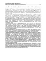
The effect of the crystal orientation on the shear strain rate is presented
in Fig. 7.13. The obtained curves exhibit initially a decreasing primary creep
rate, followed by a creep rate minimum and then a slow increase in the shear
rate after the minimum. An incubation period for creep is not observed.
The primary creep begins with a relatively high strain rate in both systems.
Initially the macroscopic shear system {111} < 110 > deforms by a factor
Fig. 7.13 The shear strain rate as a function of shear strain
in the CMSX6 superalloy. B, The slip system {111} < 110 >;
C, the slip system {100} < 010 >. Temperature 1298K,
stress 85MPa. Experimental data from Ref. [44].
126 7 Single Crystals of Superalloys
of five faster than the system {100} < 010 >. This difference between creep
rates increases during deformation. At the minimum creep rate the system
{111} < 110 > is deformed by a factor of ten faster than the crystalline system
{100} < 010 >.
Recall that the repetition factor is 48 for the former slip system and 18
for the other. Furthermore, the {111} type slip plane is the most close-packed
plane in the face-centered crystalline lattice. The distance between the nearest
parallel {111} planes is maximal in the fcc lattice. Thus, this is an expected
result.
During the primary creep a considerable part of the dislocations on the
{111} < 110 > slip system is associated with long dislocation segments.
Their Burgers vector was found to be of the type a/2[0
¯
11]. After a minimum
shear rate the dislocation segments enter the γ
interface.
A common microstructural feature of both macroscopic crystalline shear
systems in the above quoted study is that cutting of γ
particles is not observed
during primary creep but does occur after the shear rate minimum. This is
also typicalforther superalloys inthe higher temperature, lowerstress regime.
Macroscopic shear loading of the CMSX-6 superalloy results in slip in sev-
eral microscopic systems of type {111} < 110 > and {100} < 100 >.
Slip on {111} < 110 > systems is clearly favored in the case of the
(111)[01
¯
1] macroscopic system compared with the (001)[100]. In Table 7.3
are listed ratios of the resolved to the applied shear stresses calculated for all
microscopic slip systems.
The shear creep deformation is revealed to be always associated with the
multiple slip. The single slip (which sometimes is intuitively associated with
the pure shear deformation) is never observed.
Thus, matrix channel deformation always precedes the cutting of the γ
particles. The γ/γ
-interface represents an obstacle to the motion of channel
Tab. 7.3 Ratios of resolved to applied shear stresses in the 12
crystallographic {111} < 110 > slip systems for the two macros-
copic crystallographic shear systems (111)[01
¯
1] and (001)[100].
Reprinted from Ref. [44] with permission from Elsevier Science Ltd.
Macroscopic Number of microscopic Ratio of resolved to
system slip systems applied stress
(111)[01
¯
1] 1 1.00
2 0.67
4 0.50
1 0.33
4 0.17
(001)[100] 8 0.41
4 0.00
7.3 Deformation at Higher Temperatures 127
dislocations. In order to start pairwise cutting a second channel dislocation
segment must approach the first segment against the repulsive forces, which
the two segments of equal sign exert on each other (see Fig. 6.18). This re-
sults in a critical interface stress for cutting. It is important that cutting of
γ
particles can only start when the resolved shear stress, which acts on two
interface dislocation segments, exceeds the critical interface stress.
The dominant mechanism of strain is likely to be a function of the applied
loading condition. Crystal twin formation occurs in superalloy CMSX-4 un-
der unaxial load [45]. The twinning was observed during the compression,
demonstrating a mode distinction from results of the tensile tests.
The dislocation-free γ
particles are resistant to shearing by dislocations in
the temperature range 1073 to 1123K under compressing stresses of 550MPa
or lower. This was observed by Pollock and Argon [43] for the CMSX-3 su-
peralloy single crystals. The incubation period lasts for 4h at 1073K, while
at 1123K it is reduced to about 10 min. During the incubation stage the
grown-in dislocations serve as sources, and deforming dislocations spread
from these areas throughout areas that were previously dislocation free. Dur-
ing the primary creep the material continues to be filled by dislocations. All
creep deformation is accomplished by movement of the dislocations on {111}
planes through matrix channels. The movement of dislocations through ma-
trix channels seems to be a general tendency. It is related to high levels of
misfit stresses present in the matrix due to coherent precipitates. When the
steady-state creep is reached the matrix is completely filled with dislocations.
The multiple slip systems are activated during the steady-state stage. There
are very few dislocations left which are not associated with the three-dimen-
sional network.
We have discussed the formation of the dislocation sub-boundaries in the
matrix in Section 6.1, see Figs. 6.4 and 6.7. It turns out that this phenomenon
is intrinsic to single crystals of superalloys as well as to polycrystals. However,
in the former case, dislocations fill the narrow channels between dendrites.
The structure of cast single crystals is more heterogeneous than that of poly-
crystals.
The spacing of dislocations in the network of stressed specimens was found
to be in the range 50–120nm. Dislocations of the network lie in the {111}
planes. The networks that consist of a/2 < 110 > slipping dislocations are
a common characteristic of the steady-state stage creep. Dislocations of this
type have been observed in many electron microscopy studies.
During the later stages of steady-state creep the γ
particles are sometimes
sheared. In the tertiary stage creep strain is accumulated in the matrix and
shearing increase steadily. The particles become coarse at the same time.
Srinivasan et al. [46] investigated the dislocation cutting of the γ
particles
in the single-crystal superalloy CMSX-4. Shear creep curves were obtained at
128 7 Single Crystals of Superalloys
1293K under shear stress 80MPa for the macroscopic crystal shear system
(111)[01
¯
1]. The dislocation density of the produced single crystals is low. The
γ channels are filled with dislocations in the early stage of high-temperature
deformation of the GMSX-4 superalloy. γ
particles are free from dislocations.
The increase in dislocation density in the γ channels (the hardening process)
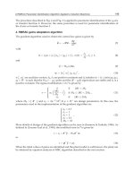
is accompanied by the annihilation (the recovery process). Dislocations from
two intersecting γ channels move towards the γ corner where they annihilate
each other (Fig. 7.14). It is obvious that the climb of dislocation edge compo-
nents is necessary in order for this process to occur. The cutting of γ
particles
decreases the dislocation density in the γ channels. The minimum creep rate
corresponds to this mechanism. Later the morphological instability of the
Fig. 7.14 Annihilation of dislocations in a cast superalloy
single crystal. (a) Motion of dislocation of opposite signs
in the γ channel; (b) motion due to cutting of γ
particles.
Reprinted from Ref. [46] with permission from Elsevier
Science Ltd.
7.4 On the Composition of Superalloys 129
γ/γ
system makes it easy for dislocations to enter the γ channel, and as a
result the tertiary stage of creep begins.
The transmission microscopy investigations show that two partial γ chan-
nel dislocations with different Burgers vectors combine and form an a[010]
superdislocation in the γ
phase. Two possible scenarios of this process have
been proposed:
a/2(111)[01
¯
1] + a/2(1
¯
11)[011] → a[010] (7.3)
or
a/2(111)[01
¯
1] + a/2(1
¯
11)[0
¯
1
¯
1] → a[00
¯
1] (7.4)
The separation distance between the individual a/2 < 110 > dislocations
is determined from the electron micrograph images to be 2.5nm.
The authors [46] say that the a[010] superdislocation has a noncompact
core and can only move by combined slip and climb processes. The second
noncompact superdislocation is of the type [00
¯
1]. The movement of both types
can be either “self-fed" or externally coupled. In the former case the vacancies
produced by one superpartial are adsorbed by the other partner. A coupled
movement of these dislocations allows vacancy equilibrium to be maintained
everywhere. The vacancy equilibrium can also be maintained by a coupling
between a rafting and a climb-controlled γ
cutting.
The authors believe that the dislocation pairs can only move when a disloca-
tion climb contributes to the process significantly. They estimate the a/2[01
¯
1]
climb velocity to be approximately 4 × 10
−8
ms
−1
. The dislocation density
was assumed to be 10
11
m
−2
. The secondary creep rate is calculated to be
4.9 × 10
−7
s
−1
. This agrees satisfactorily with the experimentally observed
value of the secondary creep rate. This result implies that the cutting of the γ
phase may indeed be a possible rate-controlling step in the high-temperature
and low-stress creep of single crystals.
7.4
On the Composition of Superalloys
Some data about the influence of alloying elements on the strength of nickel-
based superalloys are available in the literature for a limited number of ele-
ments. The rate of solution hardening per at.% of solute, dσ/dc, was mea-
sured at 77K.
The coefficient dσ/dc in MPa (at.%)
−1
is equal to 6.5 for titanium, 15.0 for
molybdenum, 43.0 for tantalum and 24.8 for tungsten [34].
It is appropriate to mention briefly the current trends in the development
of superalloy compositions (see Table S1).
130 7 Single Crystals of Superalloys
• The concentration of titanium has decreased. Some contemporary superal-
loys do not contain any titanium (EI867, Rene N5, Rene N6, MC534, TMS-
75, TMS-138). Titanium increases the energy of the anti-phase boundary of
the γ
phase, which makes the cutting of particles by dislocations more diffi-
cult. However, titanium atoms are bigger than aluminum atoms. Therefore
they induce an increase in the γ
parameter and cause an increase in the
γ/γ
misfit stresses.
• The concentration of chromium has decreased over the last decades. Su-
peralloys of the first and second generation contained up to 10–20 wt.%
chromium. Superalloys of the third and fourth generations have a lower
chromium content 2–3% (CMSX-10, CMSX-10M, TMS-75, TMS-138, Rene
N6).
• Addition of rhenium and ruthenium are under investigation for superalloys
which must withstand high stresses at temperatures from 1273 to 1373K
(GMSX-4, GMSX-10, TMS-138, Rene N6 and others). The reason for the
positive influence of the Re and Ru additions has not been studied suffi-
ciently. It is possible that these elements make the lattice γ/γ
misfit more
negative (see below).
• The volume fraction of the γ
phase in contemporary superalloys is greater
than 50%. The maximum rupture life of single crystals is found with a γ
fraction as high as 60 to 75%.
7.5
Rafting
At temperatures above 1273K the γ
morphology becomes unstable. Under
the combined influence ofhigh temperature and centrifugal stresses the cubic
particles are transformed into flat shapes, which are called rafts. At 1423K,
for example, the evolution of the γ/γ
structure from cuboidal to a plate-like
structure takes place at a very early stage of the creep strain.
The driving force for rafting has been shown to be proportional to the
applied stress, to the γ/γ
-misfit and to the difference in their elastic constants
[47]. It has also been found that the direction of rafting depends upon the
direction of loading and on the sign of the lattice misfit.
The rafted structure seems to resist creep strain under low stresses only. It
appears that rafting accelerates the creep more often than not.
A scheme illustrating the rafting process is shown in Fig. 7.15 [48]. Defor-
mation is different in the horizontal and vertical channels. The misfit strain
is usually negative at high temperature. The negative misfit implies that the
7.5 Rafting 131
Fig. 7.15 Rafting process in a single-
crystal superalloy. (a) Sketch illustrating
stresses in γ channels. The squares rep-
resent the cubic γ
particles. The tensile
stress is applied in a negative misfit alloy.
(b) Morphology of the γ
phase as a result
of rafting. Reprinted from Ref. [48] with
permission from Elsevier Science Ltd.
γ channels parallel to the interface must be loaded in compression. At the
same time the stress due to misfit can be higher than that due to the applied
stress. The total stress results in the change of the cuboid shape. γ
precipi-
tates take on a pancake shape with the flat direction is perpendicular to the
tension loading direction.
132 7 Single Crystals of Superalloys
Fig. 7.16 Electron micrograph showing dislocation networks
in the CMSX-4 superalloy. T = 1150K, σ = 100MPa, rupture
after 10.8% strain. Reprinted from Ref. [41] with permission
from Elsevier Science Ltd.
Reed et al. [41] studied the deformation of the CMSX-4 superalloy at temper-
atures above 1273K; the < 001 > ±10
◦
oriented crystals were investigated.
Examination of specimens by transmission electron microscopy revealed
that a well-developed network of dislocations has already been formed af-
ter 10 h. With increasing deformation the networks become more regular
(Fig. 7.16). The average cell size of the equilibrium network is about 50 nm.
Families of six different dislocations form the cells of the network as shown
in Fig. 7.17. Dislocation activity decreases and the networks become more sta-
Fig. 7.17 Scheme of the dislocation network seen in Fig. 7.16.
Reprinted from Ref. [41] with permission from Elsevier Science
Ltd.