Mechanics of Materials 1 Part 14 pdf
Bạn đang xem bản rút gọn của tài liệu. Xem và tải ngay bản đầy đủ của tài liệu tại đây (3.29 MB, 70 trang )
412 Mechanics of Materials 2
§10.3
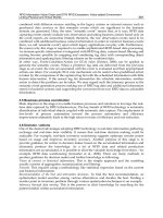
Fig. 10.18. Variation of elastic stress concentration factor Kt for a hole in a tensile bar with varying d/t ratios.
failure -both must therefore be considered.
i.e. Maximum stress = nominal stress x stress concentration factor.
If load on the bar is increased sufficiently then failure will occur. the crack emanating
from the peak stress position at the edge of the hole across the section to the outside (see
Fig. 10.19).
(0)
(b)
Fig. 10.19. Tensile bar loaded to destruction -crack initiates at peak stress concentration position at the hole edge.
Other geometric factors will affect the stress-concentration effect of discontinuities such
as the hole, e.g. its shape. Figure 10.20 shows the effect of various hole shapes on the s.c.f.
achieved in the tensile plate for which it can be shown that, approximately, Kt = 1 + 2(A/B)
where A and B are the major and minor axis dimensions of the elliptical holes perpendicular
and parallel to the axis of the applied stress respectively. When A = B, the ellipse becomes
the circular hole considered previously and Kt ~ 3.
For large values of B, i.e. long elliptical slots parallel to the applied stress axis, stress
concentration effects are reduced below 3 but for large A values, i.e. long elliptical slots
perpendicular to the stress axis. s.c.f.'s rise dramatically and the potentially severe effect of
slender slots or cracks such as this can readily be seen.
$10.3
Contact Stress, Residual Stress and Stress Concentrations
9
I
2
3
4
A/B
413
-4
Fig.
10.20.
Effect
of
shape
of
hole
on
the stress concentration factor
for
a
bar with a transverse hole.
This is, of course, the theory of the perforated toilet paper roll which should tear at the
perforation every time-which only goes to prove that theory very rarely applies perfectly
in every situation!! (Closer consideration of the mode of loading and material used in this
case helps to defend the theory, however.)
10.3.1.
Evaluation
of
stress concentration
,fiic.tor.s
As
stated earlier, the majority of the
work
in
this text is devoted to consideration
of
stress situations where stress concentration effects are not present, i.e. to the calculation of
nominal stresses. Before resulting stress levels can be applied to design situations, therefore,
it is necessary for the designer to be able
to
estimate
or
predict the stress concentration
factors associated with his particular design geometry and nominal stresses.
In
some cases
these have been obtained analytically but
in
most cases graphs have been produced for
standard geometric discontinuity configurations using experimental test procedures such as
photoelasticity, or more recently, using finite element computer analysis.
Figures 10.21 to 10.30 give stress concentration factors for fillets, grooves and holes under
various types of loading based upon a highly recommended reference volume'57). Many
other geometrical
forms
and loading conditions are considered
in
this and other reference
texts(60) but for non-standard cases the application of the photoelastic technique is also highly
recommended (see
$6.1
2).
The reference texts give stress concentration factors not only for two-dimensional plane
stress situations such as the tensile plate but also for triaxial stress systems such as the
common case of a shaft with a transverse hole or circumferential groove subjected to tension,
bending or torsion.
414
Mechanics
of
Materials
2
$10.3
IO1
I
I
I
I
I I
0001
005
010
015
020
025
0
r
/d
0
Fig.
10.21.
Stress concentration factor
Kt
for
a stepped flat tension
bar
with shoulder fillets.
Figures
10.31, 10.32
and
10.34
indicate the ease with which stress concentration positions
can
be
identified within photoelastic models as the points at which the fringes
are
greatest
in number and closest together. It should be noted that:
(1)
Stress concentration factors
are
different for a single geometry subjected to different types
of loading. Appropriate
Kt
values must therefore be obtained for each type of loading.
Figure
10.33
shows the way in which the stress concentration factors associated with a
groove in a circular bar change with the type of applied load.
(2)
Care must be taken that stress concentration factors are applied to nominal stresses
calculated on the same basis as that of
the
s.c.f. calculation itself, i.e. the same cross-
sectional area must be used-usually the net section left after the concentration has
been removed. In the case of the tensile bar of Fig.
10.15
for example,
anom
has been
taken as
P/(b
-
d)t. An alternative system would have been to base the nominal stress
anom
upon the full ‘un-notched’ cross-sectional area i.e.
anom
=
P/t.
Clearly, the stress
concentration factors resulting from this approach would be very different, particularly
as the size of the hole increases.
(3)
In the case of combined loading, the stress calculated under each type of load must be
multiplied
by
its own stress concentration factor. In combined bending and axial load,
for example, the bending stress
(oj,
=
My/Z)
should be multiplied by the bending s.c.f.
and the axial stress
(ad
=
P/A)
multiplied by the s.c.f. in tension.
410.3
Contact Stress, Residual Stress and Stress Concentrations
415
1.01
I
I
1
I
I
I
0
0.01
0.05
0.10
0
I5
020
0.25
I
r/d
Fig.
10.22.
Stress concentration factor
K,
for a stepped flat tension bar with shoulder fillets subjected
to
bending.
11
L
1.0
0
005
010
015
Ox)
025
0
r/d
0
Fig.
10.23.
Stress concentration factor
K,
for
a round tension bar with a
U
groove.
416
Mechanics
of
Materials
2
910.3
IO
:3:
I1
0
005
010
015
020
025
C
r/d
0
Fig. 10.24. Stress concentration factor
K,
for
a round bar with a
U
groove subjected
to
bending.
Fig. 10.25.
IO
'
'I
0
005
010
Ob
OX,
025
030
r/d
Stress concentration factor
K,
for
a
round bar with a
U
groove subjected
to
'
torsion.
$10.3
Contact Stress, Residual Stress and Stress Concentrations
417
I1
-
IO
-
9-
8-
2
7-
5
*
6-
5-
4-
K,p
based
on
gross
seclion
K,,
based
on
net section
0
01
02
03
04
05
06
07
a
/d
Fig. 10.26. Stress concentration factor
K,
for a round bar
or
tube with
a
transverse hole subjected
to
tension.
I
K,,bosed
on
grors
section
I
K,
bod
on
net
section
1
I
91
I
I
Assunling
rclu~
hole
cross-section
I
I
I
I
1
1
I
I
0
01
02
03
04
OS
06
07
a/d
Fig. 10.27. Stress concentration factor
Kt
for a round bar
or
tube with a transverse hole subjected to bending.
418
Mechanics
of
Materials
2
45
an
Ill
P- -P
-x
K,
values
am
approximate
35-
K+=v,,/o-
om=
4p/ud2
K,
30-
D/d
=3
1.5
I
.2
20
I5
I.
02
-1
01
IO
1
I
001
005
010
015
020
025
1
910.3
r/d
Fig.
10.28.
Stress concentration factor
K,
for a round bar with shoulder fillet subjected to tension.
5.0
1.01
I
I
I
I I
0
00
0.05
0.K)
0.15
0.20
02s
1
r/6
50
Fig.
10.29.
Stress concentration factor
K,
for a stepped round bar with shoulder fillet subjected to bending.
§10.3
419
Contact Stress, Residua/ Stress and Stress Concentrations
Fig. 10.30. Stress concentration factor Kt for a stepped round bar with shoulder fillet subjected to torsion
Fig. 10.31. Photoelastic fringe pattern of a portal frame showing stress concentration at the corner blend radii
(different blend radii produce different stress concentration factors)
§10.3
420
Mechanics of Materials 2
Fig. 10.32. Photoelastic fringe pattern of stress distribution in a gear tooth showing stress concentration at the
loading point on the tooth flank and at the root fillet radii (higher concentration on the compressive fillet). Refer
also to Fig. 10.45.
10.3.2. Saint-Venant's principle
The general problem of stress concentration was studied analytically by Saint- Venant who
produced the following statement of principle: "If the forces acting on a small area of a body
are replaced by a statically equivalent system of forces acting on the same area, there will be
considerable changes in the local stress distribution but the effect at distances large compared
with the area on which the forces act will be negligible". The effect of this principle is best
demonstrated with reference to the photoelastic fringe pattern obtained in a model of a
beam subjected to four-point bending, i.e. bending into a circular arc between the central
§10.3
421
Contact Stress, Residual Stress and Stress Concentrations
Fig. 10.33. Variation of stress concentration factors for a grooved shaft depending on the type of loading.
Fig. 10.34. (a) Photoelastic fringe pattern in a model of a beam subjected to four-point bending (i.e. circular arc
bending between central supports): (b) as above but with a central notch.
422
Mechanics
of
Materials
2
$10.3
supports
-
see Fig. 10.34(a).
If
the moment could have been applied by some other means
so
as to avoid the contact at the loading points then the fringe pattern would have been a
series of parallel fringes, the centre one being the neutral axis. The stress concentrations
due to the loading points are clearly visible as is the effect of these on the distribution of
the
fringes and hence stress. In particular, note the curvature of the neutral axis towards the
inner loading points and the absence
of
the expected parallel fringe distribution both near to
and outside the loading points. However, for points at least one depth of beam away from
the stress concentrations (St. Venant) the fringe pattern is unaffected, the parallel fringes
remain undisturbed and simple bending theory applies.
If
either the beam length is reduced
or further stress concentrations (such as the notch of Fig.
10.34(b))
are introduced
so
that
every part
of
the beam is within “one depth” of a stress concentration then at no point will
simple theory apply and analysis
of
the fringe pattern is required for stress evaluation-there
is no simple analytical procedure.
Similarly, in
a
round tension bar the stresses at the ends will be dependent upon the
method of gripping or load application but within the main part of the bar, at least one
diameter away from the loading point, stresses can again be obtained from simple theory.
To the other extreme comes the case of a screw thread. The maximum s.c.f. arises at the
first contacting thread at the plane of the bearing face of the head or nut and up to
70%
of
the load
is
carried by the first two or three threads. In such a case, simple theory cannot be
applied anywhere within the component and the reader is referred
to
the appropriate B
.S.
Code of Practice and/or the work
of
Brown and Hi~kson(~~).
10.3.3.
Theoretical considerations
of
stress concentrations due to concentrated loads
A
full treatment of the local stress distribution at points of application of concentrated load
is beyond the scope of this text. Two particular cases will be introduced briefly, however, in
order that the relevant useful equations can be presented.
(a) Concentrated load
on
the edge
of
an infinite plate
Work by St. Venant, Boussinesq and Flamant (see
$8.7.9)
has led to the development of
a theory based upon the replacement of the concentrated load by a radial distribution
of
loads around
a
semi-circular groove (which replaces the local area of yielding beneath the
concentrated load) (see Fig.
10.35).
Elements in the material are then, according to Flamant,
subjected to a radial compression of
2P cos
e
a,
=
~
nbr
with
b
=
width of plate
This produces element Cartesian stresses of:
2Px2y
-
-
2~
cos sin2
0
-
.2
a,,
=
a,
sin
0
=
-
nbr nb(x2
+
y2)2
-2~
cos3
e
-
-2~~3
-
2
cTyv
=
a,
cos
e
=
nbr
nb(x2
+
y2)2
2Pxy2
-_
-
2~
sin
e
cos2
8
T~.?
=
a,
sin
0
cos
0
=
-
nbr
b(x2
+
y2)*
(10.26)
(10.27)
(10.28)
(10.29)
$10.3
Contact Stress, Residual Stress and Stress Concentrations
423
I‘
Fig.
10.35.
Elemental stresses due to concentrated load
P
on the edge
of
an
infinite plate
(6) Concentrated load
on
the edge
of
a beam in bending
In this case a similar procedure is applied but, with a finite beam, consideration must be
given to the horizontal forces set up within the groove which result in longitudinal stresses
additional to the bending effects.
The total stress across the vertical section through the loading point (or groove) is then
given by the so-called
“Wilson-Stokes equation”.
(10.30)
where
d
is the depth of the beam,
b
the breadth and
L
the span.
This form
of
expression can be shown to indicate that the maximum longitudinal stresses
set up are, in fact, less than those obtained from the simple bending theory alone (in the
absence of the stress concentration).
10.3.4.
Fatigue stress concentration factor
As
noted above, the plastic flow which develops at positions
of
high stress concentration
in
ductile materials has a stress-relieving effect which significantly nullifies the effect of the
stress raiser under static load conditions. Even under cyclic or fatigue loading there is a
marked reduction in stress concentration effect and this is recognised by
the
use of a fatigue
stress concentration factor
Kf
.
In the absence of any stress concentration (i.e. for
K,
=
1)
materials exhibit an
“endurance
limit”
or
“fatigue limit”
-
a defined stress amplitude below which the material can withstand
an indefinitely large (sometimes infinite) number of repeated load cycles. This is often
referred to as the un-notched fatigue limit
-
see Fig. 10.36.
For
a totally brittle material
in
which the elastic stress concentration factor
K,
might be
assumed to have its full effect, e.g.
K,
=
2,
the fatigue life or notched endurance limit would
be reduced accordingly. For materials with varying plastic flow capabilities, the effect of
stress-raisers produces notched endurance limits somewhere between the un-notched value
and that of the ‘theoretical’ value given by the full
K,
-
see Fig. 10.36, i.e. the fatigue stress
concentration factor lies somewhere between the full
K,
value and unity.
424
Mechanics
of
Materials
2
Stress
$10.3
amplitude
(0)
Notched fatigue
curve
Un
.
ncided
Sn
Notched
Sn
meoretica
notched
Sn
(K,
=
2)
1
I
I
1
I
I,
lo3
104
lo5
io6
io7
io8
n
(cycles)
Fig.
10.36.
Notched and un-notched fatigue curves.
If the endurance limit for a given number
of
cycles,
n,
is denoted by
S,
then the fatigue
stress concentration factor is defined as:
&for unnotched material
&for
notched material
Kf
=
(10.31)
Kf
is sometimes referred to by the alternative titles of
‘yatigue strength reduction
factor”
or, simply, the
“jiztigue notch factor”.
The value of
Kf
is normally obtained from fatigue tests on identical specimens both with
and without the notch
or
stress-raiser for which the stress concentration effect is required.
It is well known (and discussed in detail in Chapter 11) that the fatigue life of components
is affected by a great number of variables such as mean stress, stress range, environment,
size effect, surface condition, etc
.,
and many different approaches have been proposed to
allow realistic estimations of life under real working conditions as opposed to the controlled
laboratory conditions under which most fatigue tests are carried out. One approach which
is relevant to the present discussion is that proposed by Lipson
&
Juvinal(60) which utilises
fatigue stress concentration factors,
Kf
,
suitably modified by various coefficients to take
account of the above-mentioned variables.
10.3.5.
Notch sensitivity
A
useful relationship between the elastic stress concentration factor
Kt
and the fatigue
notch factor
Kf
introduces a
notch sensitivity
q
defined as follows:
Kf
-
1
Kr
-
1
Kfs
-
1
Kls
-
1
q=-
or, in shear,
q
=
___
which may be re-written in terms of the fatigue notch factor as:
Kf
=
1
+
q(K,
-
1)
with
0
<
q
<
1
(10.32)
It will be seen that, at the extreme values of
q,
eqn. (10.32) is valid since when
q
=
1
the
full effect of the elastic stress concentration factor
K,
applies and
Kf
=
Kt;
similarly when
q
=
0
and full ductility applies there is, in effect, no stress concentration and
Kf
=
1
with
the material behaving in an unnotched fashion.
0
10.3
Contact Stress, Residual Stress and Stress Concentrations
425
The value of the notch sensitivity for stress raisers with a significant linear dimension
(e.g. fillet radius)
R
and a material constant
“a”
is given by:
1
4=
(I+
3
(10.33)
i-
Ouenched
and
tempered
sieel
Annealed or normalized steel
Averaqe-aluminum
alloy
(bars and sheets1
Note
Approximate
values
(note shcded bond
1
I.
NM
verified
for
very
01
deep notches
t/r>4
I
I I
I
1
I
I
11
I2
3
4
5
6
I0
9
10
Notch rodiur (Rm)
Fig.
10.37.
Average fatigue notch sensitivity
q
for various notch radii and materials.
Typically,
a
=
0.01 for annealed or normalised steel,
0.0025
for quenched and tempered
steel and
0.02
for aluminium alloy. However, values of
“a”
are not readily available for a
wide range of materials and reference should be made to graphs of
q
versus
R
given by both
Peterson(57) and Lipson and Juvinal(60).
The stress and strain distribution in a tensile bar containing a “through-hole” concentration
are
shown in Fig.
10.38
where the elastic stress concentration factor predictions
are
compared
with those taking into account local yielding and associated stress redistribution.
,Actual
strain
bed
m
K,
stress
and
stmin
Fig.
10.38.
Effect of a local yielding and associated stress re-distribution on the stress and strain concentration at
the edge of a hole in a tensile bar.
10.3.6.
Strain concentration
-
Neuher’s rule
Within the elastic range, the concentration factor expressed in terms of strain rather than
stress is equal to the stress concentration factor
K,.
In the presence
of
plastic flow, however,
the elastic stress concentration factor is reduced to the plastic factor
K,
but local strains
clearly exceed those predicted by elastic considerations
-
see Fig. 10.39.
426
Mechanics
of
Materials
2
$10.3
A strain concentration factor can thus be defined as:
maximum strain at the notch
nominal strain at the notch
K,
=
Stress
u
NB
Actual stress
Elastic
stress
uE
-
-
Slroin
c
,%
(e,
Slroin
c
~ioshc strain ktual stroin
Fig.
10.39.
Comparison
of
elastic and plastic stresses and strains.
the value of
K,
increasing as
the
value of
K,
decreases. One attempt to relate the two factors
is known as
“Neuher’s Rule”,
viz.
KpK,
=
K:
(10.34)
It is appropriate here to observe that recent research
in
the fatigue behaviour of materials
indicates that the strain range of fatigue loading may be more readily related to fatigue life
than
the
stress range which formed the basis of much early fatigue study. This is said to be
particularly true of low-cycle fatigue where, in particular, the plastic strain range is shown
to be critical.
10.3.7.
Designing to reduce stress concentrations
From the foregoing discussion it should now
be
evident that stress concentrations are
critical to the life of engineering components and that fatigue failures, for example, almost
invariably originate at such positions. It is essential, therefore, for any design to be successful
that detailed consideration is given to the reduction of stress concentration effects to an
absolute minimum.
One important rule
in
this respect is concerned with the initial placement of the stress
concentration. Assuming that some freedom exists as to the position of e.g. oil-holes,
keyways, grooves, etc., then
it
is essential that these be located at positions where the
nominal stress is as low as possible. The resultant magnitude of stress concentration factor
x
nominal stress is then also a minimum for a particular geometry of stress raiser.
In
situations where
no
flexibility exists as to the position of the stress raiser then one of
the procedures outlined below should
be
considered.
In
many cases a qualitative assessment
of the benefits, or otherwise, of design changes is readily obtained by sketching the lines of
stress flow through the component as
in
Fig.
10.17.
Sharp changes
in
flow direction indicate
high stress concentration factors, smooth changes in flow direction are the optimum solution.
The following standard stress concentration situations are common
in
engineering applica-
tions and procedures for reduction of the associated stress concentration factors are introduced
for each case. The procedures, either individually or
in
combination, can then often be applied
to produce beneficial stress reduction
in
other non-standard design situations.
510.3 Contact Stress, Residual Stress and Stress Concentrations
427
(a) Fillet radius
Probably the most common form of stress concentration is that arising at the junction of
two parts of a component of different shape, diameter, or other dimension. In almost every
shaft, spindle, or axle design, for example, the component consists of a number of different
diameter sections connected by shoulders and associated fillets.
If Fig. 10.40(a) is taken to be either the longitudinal section of a shaft or simply a flat
plate, then the transition from one dimension to another via the right-angle junction is
exceptionally bad design since the stress concentration associated with the sharp corner is
exceedingly high.
In
practice, however, either naturally due to the fact that the machining
tool has a finite radius, or by design, the junction is formed via a fillet radius and the wise
designer employs the highest possible radius of fillet consistent with the function
of
the
component
in
order to keep the s.c.f. as low as possible. Whilst, historically, circular arcs
have generally been used for fillets, other types of blend geometry have been shown to
produce even further reduction of s.c.f. notably elliptical and streamline fillets(6’), the latter
following similar contours to those of a fluid when
it
flows out of a hole in the bottom of a
tank. Fig. 10.41 shows the effect of elliptical fillets on the s.c.f. values.
Where wider geometry
can
be
changed
I
(a)
Sharp
(909
fillet
-/
Toper
f
11
let
Large
blend
mdius
Where
shoulder
must
be
maintoned
r
Ungrcut fillet
Relief
holes
(oa
(e)
z
Relief grooves
Fig.
10.40.
Various methods
for
reduction
of
stress concentration factor at the junction of two parts
of
a
component
of
different depth/diameter.
There are occasions, however, where the perpendicular faces at the junction need
to
be
maintained and only a relatively small fillet radius can be allowed e.g. for retention of
bearings or wheel hubs.
A
number of alternative solutions for reduction of the
s.c.f‘s
are
shown in Fig. 10.40(d) to
(f)
and Fig. 10.42.
(h) Keyways or splines
It is common to use keyways or splines
in
shaft applications to provide transfer of torque
between components. Gears or pulleys are commonly keyed to shafts, for example. by square
428
Mechanics
of
Materials
2
$10.3
D
d
b
=
112
(D-d)
I
aJb
=1
=3
I I I
I
1.5 2 2.5
3
Did
Fig.
10.41.
Variation
of
elliptical fillet stress concentration factor with ellipse geometry.
Use
of
narrow
coilor
to
reduce
concentrations
ot
fillets
Fig.
10.42.
Use of narrow collar to
reduce
stress concentration at fillet radii
in
shafts.
keys with side dimensions approximately equal to one-quarter of the shaft diameter with the
depth
of
the keyway, therefore, one-eighth of the shaft diameter.
Analytical solutions for such a case have been carried out by both Le~en(~~) and Ne~ber@~)
each considering the keyway without a key present. Neuber gives the following formula for
stress concentration factor (based on shear stresses):
Kt,
=
1
+
/:
(10.35)
where
h
=
keyway depth and
r
=
radius at the base
of
the groove or keyway (see
Fig. 10.43). For
a
semi-circular groove
K,,
=
2.
Leven, considering the square keyway specifically, observes that the s.c.f. is a function
of the keyway corner radius and the shaft diameter. For a practical corner radius
of
about
one-tenth the keyway depth
Kr,
1
3.
If fillet radii cannot be reduced then s.c.f.’s can be reduced by drilling holes adjacent to
the keyway as shown
in
Fig. 10.43(b).
The presence of a key and its associated
fit
(or lack
of)
has a significant effect on the stress
distribution and no general solution exists. Each situation strictly requires its own solution
via practical testing such as photoelasticity.
$10.3
Contact Stress, Residual Stress and Stress Concentrations
429
il-
Fig.
10.43.
Key-way dimensions and stress reduction procedure.
(c) Grooves and notches
Circumferential grooves or notches (particularly U-shaped notches) occur frequently in
engineering design in such applications as C-ring retainer grooves, oil grooves, shoulder or
grinding relief grooves, seal retainers, etc; even threads may be considered as multi-groove
applications.
Most of the available s.c.f. data available for grooves or notches refers to U-shaped grooves
and circular fillet radii and covers both plane stress and three-dimensional situations such
as shafts with circumferential grooves. In general, the higher the blend radius, the lower the
s.c.f; the optimum value being
Kt
=
2 for a semi-circular groove as calculated by Neuber’s
equation (10.35) above.
Some data exists for other forms of groove such as
V
notches and hyperbolic fillets but,
particularly in bending and tension, the latter have little advantage over circular arcs and
V notches only show significant advantage for included angles greater than 120”. In cases
where s.c.f. data for a particular geometry
of
notch are not readily available recourse can be
made to standard factor data for plates with a central hole.
Stress concentrations at notches and grooves can be reduced by the “metal
removal
-
stiffness reduction” technique utilising any procedure which improves the stress
flow, e.g. multiple notches of
U
grooves or selected hole drilling as shown in Fig. 10.44.
Reductions of the order of 30% can be obtained.
Stress-relieving
notches
Stress relieving holes
Stress- relieving
cut-outs
Fig.
10.44.
Various
procedures
for
the reduction
of
stress concentrations at notches
or
grooves.
§10.3
Mechanics of Materials 2
430
This procedure of introducing secondary stress concentrations deliberately to reduce the
local stiffness of the material adjacent to a stress concentration is a very powerful stress
reduction technique. In effect, it causes more of the stiffer central region of the component
to carry the load and persuades the stress lines to follow a path removed from the effect
of the single, sharp concentration. Figures 10.40(d) to (f), 10.42 and 10.43 are all examples
of the application of this technique, sometimes referred to as an "interference effect" the
individual concentrations interfering with each other to mutual advantage.
(d) Gear teeth
The full analysis of the stress distribution in gear teeth is a highly complex problem. The
reader is only referred in this section to the stress concentrations associated with the fillet
radii at the base of the teeth -see Fig. 10.45.
Fig. 10.45. Stress concentration at root fillet of gear tooth.
The loading on the tooth produces both direct stress and bending components on the root
section and Dolan and Broghammer(68) in early studies of the problem gave the following
formula for the combined stress concentration effect (for 20" pressure angle gears)
1
Kt=O.18+~~
510.3
Contact Stress, Residual Stress and Stress Concentrations
43
1
Later work by Jacobson(69), again for
20"
pressure angle gears, produced a series of charts
of strength factors and more recently Hearn(66.67) has carried out photoelastic studies of both
two-dimensional involute tooth forms and three-dimensional helical gears which introduce
new considerations of stress concentration factors, notably their variation in both magnitude
and position as the load moves up and down the tooth flank.
(e) Holes
From much of the previous discussion it should now be evident that holes represent very
significant stress raisers, be they in two-dimensional plates or three-dimensional bars. Fortu-
nately, a correspondingly high amount of information and data is available, e.g. Peterson(57),
covering almost every foreseeable geometry and loading situation. This includes not only
individual holes but rows and groups of holes, pin-joints, internally pressurised holes and
intersecting holes.
(J)
Oil
holes
The use of transverse and longitudinal holes as passages for lubricating oil is common in
shafting, gearing, gear couplings and other dynamic mechanisms. Occasionally similar holes
are also used for the passage of cooling fluids.
In the case of circular shafts, no problem arises when longitudinal holes are bored through
the centre of the shaft since the nominal torsional stress at this location is very small and
the effect on the overall strength of the shaft is minimal. A transverse hole, however, is a
significant source of stress concentration in any mode of loading, i.e. bending, torsion or axial
load, and the relevant s.c.f. values must be evaluated from standard reference texts(57*
Whatever the type of loading, the value of
Kr
increases as the size of the hole increases for
a given shaft diameter, with minimum values for very small holes of
2
for torsion and
3
for
bending and tension.
In cases of combined loading, a conservative estimate(58) of the stress concentration may
be obtained from values of
K,
given by either Peterson(57) or Lipson(60) for an infinite plate
containing a transverse hole and subjected to an equivalent biaxial stress condition.
One procedure for the reduction of the stress concentration at the point where transverse
holes cut the surface of shafts is shown in Fig.
10.46.
(g)
Screw threads
Again the stress distribution in screw threads is extremely complex, values of the stress
concentration factors associated with each thread being dependent upon the tooth form, the
fit between the nut and the bolt, the nut geometry, the presence or not of a bolt shank
and the load system applied. Pre-tensioning also has a considerable effect. However, from
numerous photoelastic studies carried out by the author and others(59-
6',
62)
it is clear that
the greatest stress most often occurs at the first mating thread, generally at the mating face
of the head of the nut with the bearing surface, with practically all the load shared between
the first few threads. (One estimate of the source of bolt failures shows
65%
in the thread
at the nut face compared with
20%
at the end of the thread and
15%
directly under the bolt
Mechanics of Materials 2
§10.3
432
Fig. 10.46. Procedure for reduction of stress concentration at exit points of transverse holes in shafts.
head). Alternative designs of nut geometry can be introduced to spread the load distribution
a little more evenly as shown in Figs. 10.47 and tapering of the thread is a very effective
load-distribution mechanism.
Fig. 10.47. Alternative bolt/nut designs for reduction of stress concentrations
Reduction in diameter of the bolt shank and a correspondingly larger fillet radius under
the bolt head also produces a substantial improvement as does the use of a material with
a lower modulus of elasticity for the nut compared with the bolt; fatigue tests have shown
strength improvements of between 35 and 60% for this technique.
§10.3
Contact Stress, Residual Stress and Stress Concentrations 433
Stress concentration data for various nut and bolt configurations are given by Hetenyi(62),
again based on photoelastic studies. As an example of the severity of loading at the first
thread, stress concentration factors of the order of 13 are readily obtained in conventional
nut designs and even using the modified designs noted above s.c.f.'s of up to 9 are quite
common. It is not perhaps surprising, therefore, that one of the most common causes of
machinery or plant failure is that of stud or bolt fracture.
(h) Press or shrinkfit members
There are some applications where discontinuity of component profile caused by two
contacting members represents a substantial stress raiser effectively as great as a right-angle
fillet. These include shrink or press-fit applications such as collars, gears, wheels, pulleys,
etc., mounted on their drive shafts and even simple compressive loading of rectangular faces
on wider support plates -see Fig. lO.48(a).
(a)
Fig. 10.48. (a) Photoelastic fringe pattern showing stress concentrations produced at contact discontinuities such
as the loading of rectangular plates on a flat surface (equivalent to cross-section of cylindrical roller bearing on
its support surface); (b) the reduction of stress concentra~ion at press and shrink fits.
434
Mechanics
of
Materials
2
510.3
Significant stress concentration reductions can be obtained by introducing stress-relieving
grooves or a blending fillet (or taper) in the press-fit member or the shaft
-
see Fig. 10.48.
10.3.8.
Use
of
stress concentration factors with yield criteria
Whilst stress concentration factors are defined in terms of the maximum individual stress
at the stress raiser it could be argued that, since stress conditions there are normally biaxial, it
would be more appropriate to express them in terms
of
some “equivalent stress” employing
one of the yield criteria introduced in Chapter
15.?
Since the maximum shear strain energy (distortion energy) theory of Von Mises is usually
considered to be the most applicable to both static and dynamic conditions in ductile materials
then, for a biaxial state the Von Mises equivalent stress can be defined as:
0,
=
44
-
UlUZ
+
4
(10.36)
and, since there is always a direct relationship between
(TI
and
a2
within the elastic range
for biaxial states (i.e.
(TI
=
ka2)
then
[
1-
(i)
-
-
(:)I1”
-
Then the stress concentration factor expressed in terms of this equivalent stress will be
-
ne
&=
anom
uno,
(10.37)
Except for the special case of equal bi-axial stress conditions when
(TI
=
02
and
K
=
1
the
value of
K,
is always less than
KI.
A
full treatment of the design procedures to be adopted for both ductile and brittle materials
incorporating both yield criteria (Von Mises and Mohr) and stress concentration factors is
carried out by Peterson(57) with consideration of static, alternating and combined static and
alternating stress conditions.
10.3.9.
Design procedure
The following procedure should be adopted for the design of components in order that
the effect of stress concentration is minimised and for the component to operate safely and
reliably throughout its intended service life.
(1)
Prepare a draft design incorporating the principal features and requirements of the compo-
nent. The dimensions at this stage will
be
obtained with reference to the nominal stresses
calculated on the basis of known or estimated service loads.
(2)
Identify the potential stress concentration locations.
E.J.
Hearn,
Mechanics
of
Marerials
I.
Butterworth-Heinemann,
1997
Contact Stress, Residual Stress and Stress Concentrations
435
(3)
Undertake the procedures outlined in 910.3.7 to reduce the stress concentration factors
at these locations by:
(a) streamlining the design where possible to avoid sharp changes in geometry and
producing gradual fillet transitions between adjacent parts
of
different shape and size.
(b) If fillet changes cannot be effected owing to design constraints, of e.g. bearing
surfaces, undertake other modifications to the design to produce smoother “flow” of
the stresses through the component.
(c) Where appropriate, reduce the stiffness of the material adjacent to the stress concen-
tration positions to allow greater flexibility and a reduction in the associated stress
concentration factor. This is probably best achieved by removal of material as
discussed earlier.
(4)
Evaluate the stress concentration factors for the modified design using standard
tables(57,
60)
or experimental test procedures such as photoelasticity. Depending on the
material and the loading conditions either
K,
or
Kf
may be appropriate.
(5)
Ensure that the maximum stress in the component taking into account both the stress
concentration factors and an additional safety factor to account for service uncertainties,
does not exceed the safe working stress for the material concerned.
References
1. Hertz,
H.
“On the contact of elastic solids”,
J.
reine angew Math.
(1881). 92, 56.
2. Belajef, N. M. “On the problem of contact stresses”,Bull.
Eng. Ways
ofCommunication”,
St. Petersburg, 1917.
3. Foppl, L. “Zertschrift fur Angew”,
Math undMech.
(1936), 16, 165.
4. M’Ewen, E. “The load-carrying capacity of the oil film between gear teeth”.
The Engineer,
(1948), 186,
5. Radzimovsky,
E.
I.
“Stress distribution of two rolling cylinders pressed together,”
Bulletin
408,
Eng. Exp. Sta.
6. Buckingham,
E.
“Dynamic loads on gear teeth”, ASME Special Committee on Strength of Gear Teeth. New
7. Walker, H. “A laboratory testing machine for helical gear tooth action”,
The Engineer,
(6 June 1947), 183,
8. Wellauer, E.
J.
“Surface durability of helical and herringbone gears”,
Machine Design,
May 1964.
9. Huber, M. T.
Ann. Phys. Paris
(1904). 14, 153.
234-235.
Univ. Ill., 1953.
York, 1931.
486-488.
10.
Morton W. B. and Close, L. J. “Notes on Hertz’s theory of the contact of elastic bodies”
Phil.
Mag.
(1922).
11. Thomas H.
R.
and Hoersch,
V.
A. “Stresses due to the pressure of one elastic solid on another”
Univ. Illinois
12. Fessler, H. and Ollerton, E. “Contact stresses in toroids under radial loads”,
Brit.
J.
Appl. Phys.
(1957), 8,387.
13. Ollerton, C. “Stresses in the contact zone”. Convention on Adhesion.
I.
Mech. E., London, 1964.
14. Johnson,
K.
L. “A review of the theory of rolling contact stresses”, O.E.C.D. Sub-group on Rolling Wear.
15. Deresiewicz,
H.
“Contact of elastic spheres under an oscillating torsional couple”.
/bid.
(1954), 76, 52.
16. Johnson,
K.
L. “Plastic contact stresses” BSSM Conference. Sub-surface stresses.” Nov. 1970, unpublished.
17. Lubkin,
J.
L. “The torsion of elastic spheres in contact”
J.
Appl.
Mech.
Trans ASME
(1951), 73, 183.
18.
Mindlin, R. D. and Deresiewicz,
H.
“Elastic spheres in contact under varying oblique forces”,
J.
Appl. Mech.
19. Tomlinson,
G.
A. and Gough, H.
J.
“An investigation of the fretting corrosion of closely fitting surfaces”.
20. Smith,
J.
0.
and Liu, C.
K.
“Stresses due to tangential and normal loads on an elastic solid with application
21. Lipson, C. and Juvinal,
R.
C.
Handbook
ofStress and Strength.
Macmillan, New York, 1963.
22. Meldahl, A. “Contribution to the Theory of Lubrication
of
Gears and of the Stressing of the Lubricated Flanks
6th series, 43, 320.
Eng. Exp.
Sra.
Bull.
(1930), 212.
Delft, April, 1965.
Wear
(1966), 9,4-19.
Trans ASME
(1953), 75,327.
Proc.
I
Mech. E.
(1939), 141, 223.
to some contact stress problems”,
J.
App. Mech.,
June 1953.
of Gear Teeth” Brown Boveri Review.
Vol. 28, No.
11,
Nov. 1941.
436
Mechanics
of
Materials
2
23. Dowson, D., Higginson, G. R. and Whitaker, A. V. “Stress distribution in lubricated rolling contacts”,
I.
Mech.
24. Crook, A. W. “Lubrication of Rollers”. Parts I-IV.
Phil. Trans. Roy.
Soc Ser. A250 (1958);
Ibid.,
254 (1962)
25. Dawson, P. H. “Rolling contact fatigue crack initiation in a 0.3% carbon steel”,
Proc.
I.
Mech.
E.
(1968/69),
26. Scott, D. “The effect of materials properties, lubricant and environment in rolling contact fatigue”,
I.
Mech.
27. Sherratt, F. “The influence of shot-peening and similar surface treatments on the fatigue properties of metals”,
28. Muro, H. “Changes of residual stress due to rolling contacts”,J.
Soc.
Mat. Sci.Japan
(July 1969). 18,615-619.
29. Timoshenko,
S.
P.
and Goodier,
J.
N.
Theory of Elasticity,
2nd edn. McGraw-Hill, 1951.
30. Almen,
J.
0.
“Surface deterioration
of
gear teeth”,
Trans. A.S.M.
(Jan. 1950).
31. Akaoka, J. “Some considerations relating to plastic deformation under rolling contact,
Rolling Contact
32. Heam E.
J.
“A three-dimensional photoelastic analysis of the stress distribution in double helical epicyclic
33. Roark, R. J. and Young, W. C.
“Formulas for Stress and Strain”,
5th edn., McGraw-Hill, 19
34. Heindlhofer, K.
Evaluation of Residual Stresses.
McGraw-Hill, 1948.
35. Rosenthal, and Norton, “A method of measuring tri-axial residual stresses in plates”,
Journal Welding Society,
36. Waisman, and Phillips, “Simplified measurement of residual stresses”,
S.E.S.A.,
11
(2). 29-44.
37. Mathar,
J.
“Determination of initial stresses by measuring the deformations around drilled holes”,
Trans
38. Bathgate, R. G. “Measurement of non-uniform bi-axial residual stresses by the hole drilling method”,
Strain.
39. Beaney, E. M. “The Air Abrasive Centre-Hole Technique for the Measurement of Residual Stresses”. B.S.S.M.
40. Procter,
E.
“An Introduction to Residual Stresses, their Measurement and Reliability Aspects”. B.S
S.M.
Int’l
41. Beaney, E. M. and Procter, E. “A critical evaluation of the centre-hole technique for the measurement
of
42. Milbradt, K. P. “Ring method determination of residual stresses”
S.E.S.A.,
9
(l), 63-74.
43. Durelli, A.
J.
and Tsao, C. H. “Quantitative evaluation of residual stresses by the stresscoat drilling technique”
44.
French, D. N. and Macdonald,
B.
A. “Experimental methods
of
X-ray analysis”,
S.E.S.A.,
26
(2), 456-462.
45. Kirk, D. “Theoretical aspects of residual stress measurement by X-ray diffractometry”,
Strain,
6
(2) (1970).
46. Kirk, D. “Experimental features of residual stress measurement by X-ray diffractometry”,
Sfrain,
7
(1)
(1971).
47. Andrews, K. W.
et al.
“Stress measurement by X-ray diffraction using film techniques”,
Sfrain,
10
(3) (July
48. Abuki,
S.
and Cullity, B.
D.
“A magnetic method for the determination of residual stresses”,
S.E.SA.,
28
(I),
49. Sines, G. and Carlson, R. “Hardness measurements for the determination of residual stresses”,
A.S.T.M. Bull.,
50.
Noranha, P.
J.
and Wert, J.
J.
“An ultrasonic technique for the measurement of residual stress”,
Journal Testing
51,
Kino,
G.
S.
et al.
“Acoustic techniques for measuring stress regions in materials”, Electric Power Research
52. Hearn, E. J. and Golsby, R.
J.
“Residual stress investigation of a noryl telecommunication co-ordinate selector
53. Denton, A.
A.
“The use of spark machining in the determination of local residual stress”
Strain,
3
(3) (July
54. Moore, M. G. and Evans,
W.
D. “Mathematical correction for stress in removed layers in X-ray diffraction
55.
Scaramangas, A. A.
et al.
“On the correction of residual stress measurements obtained using the centre-hole
56. Huang, T. C.
Bibliography
on
Residual Stresses.
SOC.
Auto. Eng., New York, 1954.
57. Peterson,
R.
E.
Stress Concentration Design Factors,
John Wiley
&
Sons, New York, 1953.
58. Perry, C. C. “Stress and strain concentration”, Vishay Lecture and Series, Vishay Research and Education,
59. Brown, A.
F.
C. and Hickson, V. M. “A photoelastic study of stresses in screw threads”,
Proc.
I.
Mech. E.,
60.
Lipson,
C.
and Juvinal,
R.
C.
Handbook
of Stress and Strength.
Macmillan, New
York,
1963.
E. Fatigue in Rolling Contact
(1964).
and 255 (1963).
183, Part
1.
E.
Fatigue in Rolling Contact
(1964).
B.S.S.M. Sub-surface Stresses, 1970 (unpublished).
Phenomena.
Elsevier.
gears”,
Strain
(July 1979).
(Welding supplement, 1945),
24,
295-307.
A.S.M.E.,
56
(4), (1934), 249-254.
4
(2) (1968), 20-27.
Int’l Conference: “Product Liability and Reliability”, September 1980 (Birmingham).
Conference: “Product Liability and Reliability”, September 1980 (Birmingham).
residual stresses”. C.E.G.B. report (UK), RD/B/N2492, Nov. 1972.
S.E.S.A.,
9
(I),
195-207.
1974), 111-116.
2 17- 223.
no.
180
(February 1952), pp. 35-37.
and Evaluation,
3
(2) (1975), 147- 172.
Institute NP-1043 Project 609-1. Interim Report Apr. 1979.
switch”,
S.E.S.A.,
3rd Int. Congress Experimental Mechanics, Los Angeles, 1973.
1967). 19-24.
residual stress analysis”,
S.A.E. Trans.,
66
(1958), 340-345.
method”,
Strain,
18
(3) (August 1982), 88-96.
Michigan, U.S.A.
lB, 1952-3.