Structural Steel Designers Handbook Part 8 pdf
Bạn đang xem bản rút gọn của tài liệu. Xem và tải ngay bản đầy đủ của tài liệu tại đây (565.93 KB, 80 trang )
LATERAL-FORCE DESIGN 9.21
FIGURE 9.11 Photograph of crack through the column flange and
into the column web or panel zone of connection.
of these buildings collapsed and there was no loss of life, but the economic loss was con-
siderable. This unexpected damage has caused a new evaluation of the design of moment
frame connections through the SAC Steel Project. SAC is a joint venture of SEAOC, ATC
(Applied Technology Council), and CUREE (California Universities for Research in Earth-
quake Engineering), and the joint venture is funded by FEMA. This work is still in progress,
but it is clearly leading structural engineers in new directions in the design of special steel
moment frame buildings. The work shows that great ductility is possible, but it also shows
that the engineer must exercise great care in the selection and design of members and con-
nections. The requirements that are evolving for special moment frames are briefly sum-
marized in Art. 9.7.1.
Concentric braced frames, defined in Art. 9.4, economically provide much larger
strength and stiffness than moment-resisting frames with the same amount of steel. There
are a wide range of bracing configurations, and considerable variations in structural perform-
ance may result from these different configurations. Figure 9.12 shows some concentric
bracing configurations. The braces, which provide the bulk of the stiffness in concentrically
braced frames, attract very large compressive and tensile forces during an earthquake. As a
result, compressive buckling of the braces often dominates the behavior of these frames. The
pinched cyclic force-deflection behavior shown in Fig. 9.9b commonly results, and failure
of braces may be quite dramatic. Therefore, concentrically braced frames are regarded as
stiffer, stronger but less ductile than steel moment-resisting frames. In recent years, research
has shown that concentrically braced frames can sustain relatively large inelastic deformation
without failure if greater care is used in the design and selection of the braces and the brace
connections. Concentrically braced frames, which are designed to these higher ductility stan-
dards, can be designed for smaller seismic design forces and are called special concentrically
braced frames. Different design provisions are required for ordinary concentrically braced
frames and special concentrically braced frames. These are summarized in Art. 9.7.2.
Eccentric braced frames, defined in Art. 9.4, can combine the strength and stiffness of
concentrically braced frames with the good ductility of moment-resisting frames. Eccentric
braced frames incorporate a deliberately controlled eccentricity in the brace connections (Fig.
9.13). The eccentricity and the link beams are carefully chosen to prevent buckling of the
brace, and provide a ductile mechanism for energy dissipation. If they are properly designed,
eccentric braced frames lead to good inelastic performance as depicted in Fig. 9.9c, but they
require yet another set of design provisions, which are summarized in Art. 9.7.3.
Dual systems, defined in Art 9.4, may combine the strength and stiffness of a braced
frame and shear wall with the good inelastic performance of special steel moment-resisting
frames. Dual systems are frequently assigned an R value and seismic design force that are
9.22 SECTION NINE
FIGURE 9.12 Typical configurations of concentric braced frames.
intermediate to those required for either system acting alone. Design provisions provide limits
and recommendations regarding the relative stiffness and distribution of resistance of the two
components. Dual systems have led to a wide range of structural combinations for seismic
design. Many of these are composite or hybrid structural systems. However, steel frames
with composite concrete floor slabs are not commonly used for developing seismic resistance,
even though composite floors are commonly used for gravity-load design throughout the
United States.
9.7 SEISMIC-DESIGN LIMITATIONS ON STEEL FRAMES
A wide range of special seismic design requirements are specified for steel frames to ensure
that they achieve the ductility and behavior required for the structural system and the design
forces used for the system. Use of systems with poor or uncertain seismic performance is
restricted or prohibited for some applications. Most of these requirements are specified in
the ‘‘Seismic Provisions for Structural Steel Buildings’’ of the AISC. These provisions are
either adopted by reference or they are directly incorporated into the UBC and NEHRP
provisions. However, UBC also includes supplemental provisions and clarifications which
supplement the AISC provisions. This article will provide a summary of the provisions for
moment-resisting frames, concentrically braced frames and eccentrically braced frames for
seismic applications. It should be noted that the 1992 AISC seismic provisions are directly
LATERAL-FORCE DESIGN 9.23
FIGURE 9.13 Typical configurations of eccentric braced frames. See
also Fig. 9.16.
included in the 1997 UBC, but the 1997 AISC seismic provisions are discussed in this article
since they are more current.
9.7.1 Limitations on Moment-Resisting Frames
Structural tests have shown that steel moment-resisting frames may provide excellent duc-
tility and inelastic behavior under severe seismic loading. Because these frames are fre-
9.24 SECTION NINE
quently quite flexible, drift limits often control the design. The UBC recognizes this ductility
and assigns R
ϭ 8.5 to special moment-resisting frames (Art. 9.4).
Slenderness Requirements. Special steel moment-resisting frames must satisfy a range of
slenderness requirements to control buckling during the plastic deformation in a severe earth-
quake. The unsupported length, L
b
, of bending members must satisfy
2500 r
y
L Յ (9.19)
b
F
y
where r
y
is the radius of gyration about the weak axis of the member and is the specifiedF
y
minimum yield stress, ksi, of the steel. The objective of this limit is to control lateral torsional
buckling during plastic deformation under cyclic loading. The flanges of beams and columns
must have a slenderness less than
b
52
ƒ
Յ (9.20)
2 t
ƒ
͙F
y
where b
ƒ
and t
ƒ
are the flange width and thickness, respectively. The purpose of this require-
ment is to control flange buckling during the plastic deformation expected in a severe earth-
quake. The webs of members must satisfy
d 520 PP
uu
Ͻ 1 Ϫ 1.54 for Ͻ 0.125 (9.21a)
ͫͬ
t
P
P
w
͙F
yy
y
d 191 PP
uu
Ͻ 2.33 Ϫ for Ͼ 0.125 (9.21b)
ͫͬ
t
P
P
w
͙F
yy
y
except that
d 253
Ͼ (9.21c)
t
w
͙F
y
provides a lower limit beyond which Eq. (9.21b) need not be applied. For these equations,
P
u
and P
y
are the factored applied compressive load and the yield load of the member,
is
the resistance factor, and d and t
w
are the depth and web thickness of the member. These
latter equations are required to control web buckling during the plastic deformation expected
during a severe earthquake. These limits are somewhat more conservative than the normal
compactness requirements for steel design, because of the greater ductility demand of seismic
loading.
Seismic Loads for Columns. The columns and column splices must be designed for the
possibility of uplift and extreme compressive load combinations. Two special factored load
combinations are required for this purpose when the factored axial load on the column
exceeds 40% of the nominal capacity. For axial compression, columns should have the
strength to resist
1.0 P
ϩ 0.5 P ϩ 0.2 P ϩ ⍀ P (9.22)
DL LL S HE
and for axial tension
0.9 P
Ϫ ⍀ P (9.23)
DL HE
where P
DL
, P
LL
, P
S
and P
HE
are the column loads due to dead load, live load, snow load,
LATERAL-FORCE DESIGN 9.25
and horizontal components of earthquake loading, respectively. The factor, ⍀, is an over-
strength factor which is 3.0 for steel moment-resisting frames.
Beam-to-Column Connections. In special moment-resisting frames, beam-to-column con-
nections have historically been designed as prequalified, welded flange, bolted web connec-
tions as depicted in Fig. 9.14a. The connections were used because experiments performed
20 to 30 years ago indicated that good ductility was achieved with such connections. How-
ever, as noted in Art. 9.6, cracking occurred in a number of these connections during the
Northridge earthquake. The cracking was more frequently noted in new buildings and in
buildings with relatively heavy members. There are a number of probable contributing factors
to this observed damage, and the building codes have responded to these factors. First, the
damage was more common in buildings where the lateral resistance was concentrated in
limited portions of the structure, since this concentration produces larger member sizes. The
redundancy factor described in Art. 9.4 was partly motivated by this observation. Second,
the expected yield stress of modern structural steels often widely exceeds the nominal yield
stress. This limits the ability to control the yield mechanism during severe seismic loading
and thus, may increase the potential for cracking and brittle modes of failure. As a result,
the AISC seismic design provisions now include an expected strength factor, R
y
, defined as
the ratio of the expected yield stress, F
ye
, to the specified yield stress, F
y
:
F
ye
R ϭ (9.24)
y
F
y
This value can be established through testing or, in the absence of test data, specificationR
y
defined values of between 1.1 and 1.5 are provided. R
y
is used to evaluate both the uncertainty
in material properties and how this affects the seismic performance of the building.
Many other issues including the weld electrode, the basic connection geometry, and the
construction practices used, are believe to have contributed to the observed damage. The
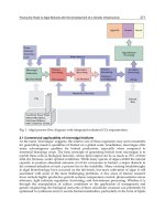
SAC Steel Project was started to address these issues and its goals are to develop reliable
methods of seismic design, repair, and retrofit for steel moment frames. This project is
completing a wide range of experimental and analytical research regarding the seismic per-
formance of steel frame buildings. The work is still in progress, but significant recommen-
dations are forthcoming. However, ‘‘Interim Guidelines: Evaluation, Repair, Modification
and Design of Welded Steel Structures’’ and ‘‘Interim Guidelines Advisory No. 1’’ by FEMA
(FEMA 267 and 267A) include many recommendations arrived at to date regarding special
steel moment-resisting frame connections. It is expected that a number of new and improved
connection types will be prequalified by this research work. However, for the present, the
structural engineer is left with a great deal of responsibility regarding the acceptability of
connections for special steel moment-resisting frames. In general, the UBC and the AISC
seismic provisions permit the use of a wide range of connections, but require that prototype
connection tests be completed to verify seismic performance of the connection before it is
used in construction. This testing requires time and the cost is not inconsequenttial. However,
the testing may often produce significant savings in the final construction cost and it relieves
the engineer of considerable uncertainty regarding the seismic performance of the building.
The testing may be avoided, if past test results of the selected connection with the same
general member sizes as used in the subject building, can be provided.
In this environment, the coverplated connection depicted in Fig. 9.14b and the reduced
beam section depicted in Fig. 9.14c are being used with some frequency since there is a
reasonable experimental data base for both connection types. The coverplated connection
significantly strengthens the connection with the goal of forcing yielding into the beam at
the end of the coverplate. This modification has worked very well in a number of past tests,
but it is an expensive connection and there also have been a few undesirable fractures with
this connection. The reduced beam section cuts away a portion of the beam flange at a short
distance from the welded flange connection so that yielding occurs within the reduced flange
9.26 SECTION NINE
FIGURE 9.14 Typical beam-to-column connectoins for special moment-resisting frames. (a) Typical pre-
Northridge connection. (b) Typical coverplated connection. (c) Typical reduced beam section connection.
LATERAL-FORCE DESIGN 9.27
FIGURE 9.15 Forces acting on a column and beam in the panel zone in a typical moment-resisting
connection during seismic loading. Forces in (a) are equivalent to those in (b).
area, well before large stresses develop at the welded connection. This alternative has also
performed well, but testing is in progress to evaluate the effects of composite slabs and the
lateral-torsional stability of the reduced section. These and other alternatives are discussed
in the FEMA 267 documents, and partial design procedures are provided there. At the end
of the SAC Steel Project, a number of different steel frame connections will likely be pre-
qualified for use in seismic design by structural engineers. These will clearly include a
number of different bolted connections as well as welded connections. However a study of
these connections is incomplete and the design procedures for the connections are not fully
developed. As a result, the structural engineer must currently rely on the experimental eval-
uation requirements of the seismic design specification.
Other Connection and Frame Issues. While many issues of connection design are now
loosely defined because of the Northridge damage, some important issues are still well
defined in the seismic specifications. Seismic bending moments in the beam cause large
shear stresses in the column web in the panel zone of the connection (Fig. 9.15). The panel-
zone shear strength, kips, may be computed from
2
3bt
ccƒ
V ϭ 0.6 Fdt 1 ϩ (9.25)
ͫͬ
yc c
ddt
bc
F
yc
is the yield stress, ksi, of the panel-zone steel; d
c
is the overall column depth, in; t is the
total thickness, in, of the panel-zone (including doubler plates); d
b
is the overall beam depth,
in; b
c
is the width, in, of the column flange; and t
cƒ
the thickness, in, of the column flange.
The panel-zone shear strength need not exceed 80% of the plastic bending capacity of the
beams intersecting the column panel zone.
Equation (9.25) takes into account the fact that the strength of the panel zone is enhanced
by the strength and stiffness of the column flanges, and that panel- zone yielding provides
good, stable energy dissipation and inelastic performance. Also, this equation encourages
panel-zone yielding over many other types of plastic deformation. Equation (9.25), however,
permits some plastic deformation of the panel zone at loads well below the design load,
since V is sometimes considerably larger than the panel-zone yield capacity,
9.28 SECTION NINE
V ϭ 0.55Fdt (9.26)
syccw
If the panel zone does not have the capacity required by Eq. (9.25), a doubler plate (Fig.
9.14a) or thicker column web is required. A minimum thickness t
z
for the combined doubler
plate and column web is prescribed:
d ϩ w
zz
t Ն (9.27)
z
90
where d
z
and w
z
are the depth between continuity plates and width between column flanges
in the panel zone. Doubler plates must be stitched to the web of the column with plug welds
to prevent local buckling of the plate, otherwise d
z
cannot be included in Eq. (9.27).
Panel-zone requirements often control the lateral resistance of steel moment-resisting
frames. However, this may cause some difficulties for structural designers. The UBC requires
computation of the story drift due to panel-zone deformation, and there is no clear, simple
method for calculating story drift in frames dominated by panel-zone yielding.
Special moment-resisting frames provide superior performance when yielding due to se-
vere seismic loading occurs in the beams rather than the columns. This strong-column, weak-
beam behavior is required, except in special cases. To ensure this behavior, the following
relationship must be satisfied, except as indicated below.
͚Z (F Ϫ ƒ)
cyc a
Ͼ 1.0 ƒ Ն 0 (9.28)
a
͚ZF
byb
where Z
b
and Z
c
are the plastic section modulus, in
3
, of the beam and the column. This
requirement need not be met when ƒ
a
Ͻ 0.3F
v
c
for all load combinations, except for those
specified by Eqs. (9.22) and (9.23), and any of the following conditions hold:
1. The joint is at the top story of a multistory frame with fundamental period greater than
0.7 second.
2. The joint is in a single-story frame.
3. The sum of the resistances of the weak-column joints is less than 20% of the resistances
for a specific story in the total frame and the sum of the resistances of the weak-column
joints in a specific frame is less than 33% of the resistances for the frame.
Research suggests that yielding of the columns results in concentration of damage in the
structural frames (Fig. 9.10) and reduces the available ductility in the structure while in-
creasing the ductility demand. However, many structural configurations quite naturally lead
to weak-column, strong-beam behavior. In addition, the issue is further complicated by con-
cern that panel-zone yielding may lead to an equivalent of weak-column, strong-beam be-
havior even though Eq. (9.28) is satisfied.
Ordinary Moment Frames. Some steel moment-resisting frames, known as ordinary mo-
ment frames, are not designed to satisfy all of the preceding conditions. In many cases, these
frames are used in less seismically active zones. Sometimes, however, they are used in
seismically active zones with larger seismic design forces; that is, they are designed with
R
ϭ 4.5. As a result, the design forces would be nearly twice as large as required for special
moment frames, but the detailing requirements are reduced. Ordinary moment-resisting
frames must satisfy some of the requirements noted above, depending upon the seismic zone
and the design forces in the structure.
9.7.2 Limitations on Concentric Braced Frames
Concentric braced steel frames are much stiffer and stronger than moment-resisting frames,
and they frequently lead to economical structures. However, their inelastic behavior is usually
LATERAL-FORCE DESIGN 9.29
inferior to that of special moment-resisting steel frames (Art. 9.6). One reason is that the
behavior of concentric braced frames under large seismic forces is dominated by buckling.
Furthermore, the columns must be designed for tensile loads and foundation uplift as well
as for compression.
Figure 9.12 shows some of the common bracing configurations for concentric braced
frames. Seismic design requirements vary with bracing configuration.
X bracing, for example, usually is very slender and has large tensile capacity and little
compressive buckling capacity. It may be an economical design for lateral loads, but it
permits concentration of inelastic deformations, and energy dissipation during major earth-
quakes is poor. As a result, X bracing is restricted to use in less seismically active zones or
very short structures in more active zones.
K bracing causes yielding in the columns during severe seismic loading. One diagonal
is in compression while the other is in tension, and the compression diagonal buckles well
before the tensile brace yields. The buckling introduces large shears and bending moments
in the columns. As a result, K bracing is prohibited in the more seismically active regions.
Because of these considerations, diagonal and chevron bracing are the primary systems
for major structures in seismically active regions of the United States.
Chevron bracing (V or inverted V, shown in Fig. 9.12) causes beam yielding during
severe seismic excitation, whereas K bracing causes column yielding. Beam flexure with
chevron bracing induces deformations of floors during a major earthquake but provides ad-
ditional energy dissipation, which may improve the seismic response during major earth-
quakes.
Diagonal bracing acts in tension for lateral loads in one direction and in compression
for lateral loads in the other direction. The ‘‘Uniform Building Code’’ requires that the
direction of the inclination of bracing with the diagonal bracing system be balanced, since
braces have much larger capacity in tension than in compression.
Buckling of Bracing. In general, the energy dissipation of concentric braced frames is
strongly influenced by postbuckling brace behavior. This is quite different for slender braces
than for stocky braces. For example, the compressive strength of a slender brace is much
smaller in later cycles of loading than it is in the first cycle. In addition, very slender braces
offer less energy dissipation but are able to sustain more loading cycles and larger inelastic
deformation than stocky braces. In view of this, the slenderness ratio of bracing is limited,
to
L 720
Յ (9.29)
r
͙f
y
where L is the unsupported length, in; r is the least radius of gyration, in; and F
y
is the yield
stress, ksi.
The compressive strength of bracing members must also be limited to 80% of the factored
nominal compressive capacity,
c
P
n
, of the brace computed by the normal AISC LRFD
design procedure. This reduction in compressive capacity is applied because of the loss of
compressive resistance expected during cyclic loading after the initial buckling cycles. How-
ever, the reduction is not used in the evaluation of the maximum forces that can be transferred
to adjacent members.
Bracing, contributing most of the lateral strength and stiffness to frames, resists most of
the seismic load. It is tempting, for economy, to design bracing as tension members only,
since steel is very efficient in tension. However, this results in poor inelastic behavior under
severe earthquake loading, a major reason for excluding X bracing from seismically active
regions. On the other hand, more energy is dissipated in a brace yielding in tension than in
a brace buckling in compression. As a result, all bracing systems must be designed so that
at least 30%, but no more than 70%, of the base shear [Eq. (9.5)] is carried by bracing
acting in tension, while the balance is carried by bracing acting in compression.
9.30 SECTION NINE
The overall and local slenderness of bracing is important. The ratio b/t of width to
thickness of single-angle struts or double-angle braces that are separated by stitching ele-
ments is limited to
b 52
Յ (9.30)
t
͙F
y
where b and t are the flange width and thickness of the angle, respectively. The slenderness
of bracing for hollow rectangular and circular tubes of high strength steel are likewise limited
so that
bh110
c
and Յ (for hollow rectangular tubes) (9.31)
tt
͙F
y
d 1300
Յ (for hollow circular tubes) (9.32)
tF
y
where t is wall thickness of the tube, d is the diameter of circular tube, and b and h
c
are the
width and depth in compression for a rectangular tube. Beyond the restrictions noted above,
the bracing may be compact or non-compact, but they must not exceed the limit for slender
members in the AISC LRFD provisions.
Strength of Connections. The strength of the connections should be stronger than the
members themselves. This assures that the energy dissipation occurs in the members rather
than the connections. For ordinary concentrically braced frames, this is achieved by first
assuring that the connections are capable of developing the brace forces produced by the
load combinations given in Eqs. (9.22) and 9.23) with the overstrength factor,
⍀, of 2.0. In
addition, the connections must be designed to resist the maximum tensile strength of the
brace considering the full uncertainty of the yield stress in the brace members. This is
accomplished by assuring that the connection resistance also exceeds R
y
F
y
A
g
, where A
g
is
the gross area of the brace and R
y
and F
y
are as defined in the moment-resisting frame
discussion (Eq. 9.24).
Selection of R. Once concentric bracing is selected for seismic design, the force reduction
factor, R, must be chosen. The discussion to this point has focused on ordinary braced frames,
which have R
ϭ 5.6, and also have the fewest restrictions on their application. This R value
is somewhat smaller than that permitted for special steel moment-resisting frames, because
concentrically braced frames are known to be dominated by brace buckling. As a result,
their resistance may deteriorate and the brace may fracture under seismic loading. There are
two major options for improving the behavior of concentrically braced frames. First, they
may be used as a dual system with a special steel moment-resisting frame, and R
ϭ 6.5.
With this system, the moment frame must be able to resist the loads which are at least 25%
of the total seismic design base shear. In addition, both the braced frame and the moment
frame must be able to resist their appropriate portion of the loading in accordance with their
relative stiffness. The braced frame is usually much stiffer than the moment frame, so that
this requirement effectively means that the dual system has a greater total resistance than
required by the basic design equations. A second alternative is the recently developed special
concentrically braced frame. The seismic performance of concentrically braced frames can
be improved if the brace can tolerate larger inelastic deformations without excessive dete-
rioration and brace or connection fracture. However, additional special detailing requirements
are needed to achieve this improvement. If these additional requirements are satisfied, R
ϭ
6.4 for special concentrically braced frames, and R ϭ 7.5 with dual systems of special
concentrically braced frames and special steel moment frames.
LATERAL-FORCE DESIGN 9.31
Special Concentrically Braced Frames. Special concentrically braced frames require that
the braced frame satisfy the requirements summarized above, but a few more restrictive
requirements are added to ensure improved ductility of the system. The slenderness of brac-
ing members must be limited to
KL 1000
Յ (9.33)
r
͙F
y
where K, L and r are the effective length coefficient, the brace length, and the controlling
radius gyration of the bracing. The bracing must be compact, and there is no reduction
applied to the compressive load capacity as used for ordinary concentrically braced frames.
The requirements for the stitching of the members are somewhat more restrictive, and a
strength analysis of the bracing member is required to ensure that the connections have
adequate strength to fully develop the bracing members. It should be noted that the provisions
for special concentrically braced frames were considerably more restrictive than the provi-
sions for ordinary braced frames in previous versions of the seismic design specifications.
However, recent changes to the seismic design specifications such as the expected yield
strength factor, R
y
, and the overstrength factor, ⍀, have narrowed the differences between
special and ordinary braced frames. As a result, the special concentrically braced frame is
an incresingly attractive option.
9.7.3 Eccentric Braced Frames
These combine the strength and stiffness of a concentric braced frame with the inelastic
performance of a special moment-resisting frame (Fig. 9.9c). The UBC permits use of an R
of 7 or 8.5 for an eccentric braced frame. This results in seismic design forces comparable
to those required for special moment-resisting frames if the fundamental period of vibration
is the same. However, braced frames are invariably stiffer than moment-resisting frames of
similar geometry and have a shorter period. This results in a somewhat larger design load
than for special moment-resisting frames under comparable conditions. (C. W. Roeder, and
E. P. Popov, ‘‘Eccentrically Braced Steel Frames for Earthquakes,’’ Journal of Structural
Division, March 1978, American Society of Civil Engineers.)
General Requirements for Ductility. There are a number of special design provisions that
must be satisfied by eccentric braced frames. As defined in Art 9.4, a link must be provided
at least at one end of each brace. The link beam should be designed so that it is the weak
link of the structure under severe seismic loading. This is done by selecting the size of the
steel section and the length of the link beam to match seismic-load design requirements.
The weak link is assured by the requirement that the brace be designed for a force at least
1.25 times the brace force necessary to yield the link beam considering the expected yield
strength (R
y
F
y
). Yielding or buckling of the columns must also be avoided. Therefore, the
column must be designed for the combined axial force of 1.1 times the sum of the yield
forces for all link beams considering the expected yield strength. In addition, the columns
must be designed for the normal factored load combinations from the AISC LRFD Speci-
fication. These brace and column design forces are needed to ensure that the brace and
column do not buckle as the link beam strain hardens during inelastic deformation.
Link Beam. Eccentrically braced frames develop good inelastic behavior because yielding
in the link beam occurs well before brace buckling or inelastic deformation of the columns,
and this yielding permits large inelastic deformations and great energy dissipation during
severe earthquakes. The link beam may yield in shear, flexure or a combination of the two
depending upon the size of the beam and the length of the link. The normal yield shear of
9.32 SECTION NINE
FIGURE 9.16 Typical connection details and stiffener arrangement for an
eccentric braced frame.
the link beam is the lesser of Y
p
or 2 M
p
/e. In this expression, M
p
, is the normal link beam
plastic moment (M
p
ϭ Z ) and e is the clear span eccentricity of the link beam. The plasticF
y
shear capacity, V
p
, of the link beam is
V
ϭ 0.60 F (d Ϫ 2 t ) t (9.34)
pyƒ w
where d, , and t
w
are the depth, flange thickness and web thickness of the link beam. Thet
ƒ
nominal yield shear and moment of the link beam may require further reduction if the axial
force in the link beam exceeds 15% of the yield axial force, but this can occur only under
very special conditions with specific brace configurations. Link beams where
1.6 M
p
e Յ (9.35)
V
p
are controlled by shear yield behavior, and they have a maximum plastic link rotational angle
of 0.08 radians. Link beams where
2.6 M
p
e Ն (9.36)
V
p
are controlled by flexural yield behavior, and they have a maximum plastic link rotational
angle of 0.02 radians. Link beams with lengths between these two limits are intermediate
links and their rotational limit is determined by interpolation. The rotational limit must be
compared to the maximum rotation predicted for the link in the analysis of the system under
seismic loading.
Stiffeners and Lateral Support of the Link Beam. The link beam is subject to both high
bending stress, high shear stress and significant inelastic deformation. As a result, it must
have lateral support to both the top and bottom flanges at both ends of the link beam. The
lateral supports must have adequate resistance to develop 6% of the expected flange force
(R
y
F
y
b
ƒ
t
ƒ
). The beam must also satisfy all of the web and flange slenderness requirements
previously noted for special moment resisting frames. Full depth web stiffeners are also
required at each end of the link beam as illustrated in Fig. 9.16. The high shear stress in the
web of the link beam results in the potential for web buckling during large inelastic cycles,
and intermediate web stiffeners are also likely to be required as shown in Fig. 9.16. Spacing
s for intermediate stiffeners for link beams with link rotation angle of 0.08 radians is
LATERAL-FORCE DESIGN 9.33
d
s ϭ 30 t Ϫ (9.37)
w
5
When the link rotation angle is 0.02 radians or less,
d
s ϭ 52 t Ϫ (9.38)
w
5
For link beams with link rotation angle between 0.02 and 0.08 radians, the spacing must be
determined by interpolation. The web stiffeners must all be full depth stiffeners, however,
the intermediate stiffeners may sometimes be lighter than the end stiffeners.
Beam Outside the Link. Special considerations are also required for the beam outside the
link. The beam outside the link must be designed for forces which are 1.1 times those caused
by the brace force necessary to yield the link beam considering the expected yield stress (R
y
F
y
) of the link beam. Lateral support and slenderness requirements are required for the beam
outside the link.
Eccentrically Braced Frames in Dual Systems. The preceding discussion has covered ec-
centrically braced frames with R
ϭ 7.0. Eccentrically braced frames may also be designed
as part of dual systems with special moment-resisting frames and R
ϭ 8.5. With dual systems,
the special moment-resisting frame must be able to resist loads which are at least 25% of
the total seismic design base shear. In addition, both the eccentrically braced frame and the
moment frame must be able to resist their appropriate portion of the loading in accordance
with their relative stiffness.
General Comments. Doubler plates and holes or penetrations are not permitted in the link
beams. The connections must be strong enough to develop fully the plastic capacity of the
link beams. Link beams that are directly connected to columns require the same experimental
verification as is presently required for special steel moment-resisting frames.
Eccentrically braced frames are a rational attempt to design steel structures that fully
develop the ductility of the steel without loss of strength and stiffness due to buckling. The
design of these frames is somewhat more complicated than that of some other steel frames,
but eccentric braced frames offer advantages in economical use of steel and seismic per-
formance that cannot be duplicated by other systems.
9.8 FORCES IN FRAMES SUBJECTED TO LATERAL LOADS
The design loads for wind and seismic effects are applied to structures in accordance with
the guidelines in Arts. 9.2 to 9.5. Next, the structure must be analyzed to determine forces
and moments for design of the members and connections. Member and connection design
proceeds quite normally for wind load design after these internal forces are determined, but
seismic design is also subject to the detailed ductility considerations described in Arts. 9.6
and 9.7. This is required for preliminary design and for interpretation and evaluation of
computer results. Approximate methods are based on physical observations of the response
of structures to applied loads. Two such methods are the portal and cantilever methods, often
used for analyzing moment-resisting frames under lateral loads.
The portal method is used for buildings of intermediate or shorter height. In this method,
a bent is treated as if it were composed of a series of two-column rigid frames, or portals.
Each portal shares one column with an adjoining portal. Thus, an interior column serves as
both the windward column of one portal and the leeward column of the adjoining portal.
9.34 SECTION NINE
FIGURE 9.17 Eight-story moment-resisting frame subjected to static lateral loading.
Horizontal shear in each story is distributed in equal amounts to interior columns, while
each exterior column is assigned half the shear for an interior column, since exterior columns
do not share the loads of adjacent portals. If the bays are unequal, shear may be apportioned
to each column in proportion to the lengths of the girders it supports. When bays are equal,
the axial load in interior columns due to lateral load is zero.
Inflection points (points of zero moment) are placed at midheight of the columns and
midspan of beams. This approximates the deflected shapes and moment diagrams of those
members under lateral loads. The location of the inflection points may be adjusted for special
cases, such as fixed or pinned base columns, or roof beams and top-story columns, or other
special situations. On the basis of the preceding assumptions, member forces and bending
moments can be determined entirely from the equations of equilibrium. As an example, Fig.
9.17 indicates the geometry and loading of an eight-story moment-resisting frame, and Fig.
9.18 illustrates the use of the portal method on the upper stories of the frame. The frame
has two interior columns. So one-third of the shear in each story is distributed to the interior
columns and half of this, or one-sixth, is distributed to the exterior columns (Fig. 9.18). The
other member forces are computed by equations of equilibrium on each subassemblage. For
example, for the subassemblage at the top of the frame in Fig. 9.18, setting the sum of the
moments equal to zero yields
9.35
FIGURE 9.18 Forces at midspan of beams and midheight of columns in the frame of Fig. 9.17 as determined
by the portal method.
9.36 SECTION NINE
lh h
S ϭ 4.17 or S ϭ 4.17 (9.39)
11
22 l
Setting the sum of the vertical forces equal to zero gives
h
A ϭϪS ϭϪ4.17 (9.40)
41
l
Setting the sum of the horizontal forces equal to zero results in
A
ϭ 25 Ϫ 4.17 ϭ 20.83 (9.41)
1
For the central top subassemblage:
lhh h
(S ϩ S ) ϭ 8.33 or S ϭ (8.33 Ϫ 4.17) ϭ 4.16 (9.42)
12 2
22ll
The remaining axial and shear forces can be determined by this procedure, and bending
moments can be determined directly from these forces from equilibrium equations.
FIGURE 9.19 Drift of a moment-resisting frame
assumed for analysis by the cantilever method.
The cantilever method is used for tall
buildings. It is based on the recognition that
axial shortening of the columns contributes
to much of the lateral deflections of such
buildings (Fig. 9.19). In this method, the
floors are assumed to remain plane, and the
axial force in each column is assumed to be
proportional to the distance of the column
from the centroid of the columns. Inflection
points are assumed to occur at midheight of
the columns and at midspan of the beams.
The internal moments and forces are deter-
mined from equations of equilibrium, as with
the portal method. The determination of the
forces and moments in the members at the
top floors of the frame in Fig. 9.17 is illus-
trated in Fig. 9.20. The lateral forces cause
overturning moments, which induce axial
tensile and compressive forces in the col-
umns. Therefore,
A
ϭϪA and A ϭϪA (9.43)
47 56
Since the exterior columns are 3 times as far
from the centroid of the columns as the in-
terior columns,
A
ϭ 3A (9.44)
45
Setting the sum of the moments equal to zero gives
hh
3lA ϩ lA ϭ 25 and A ϭ 1.25 (9.45)
45 5
2 l
Axial forces in the columns can be determined at other levels by the same procedure. Other
shear forces and bending moments can be determined by application of the equations of
equilibrium for individual subassemblages, as for the portal method.
9.37
FIGURE 9.20 Cantilever method of determining the forces at midspan of beams and midhheight of columns
in the frame of Fig. 9.17.
9.38 SECTION NINE
Analysis of Dual Systems. Approximate analysis of braced frames can be performed as if
the bracing were a truss. However, many braced structures are dual systems that combine
moment-resisting-frame behavior with braced-frame behavior. Under these conditions, an
approximate analysis can be performed by first distributing the lateral forces between the
braced-frame and moment-resisting-frame portions of the structure in proportion to the rel-
ative stiffness of the components. Braced frames are commonly very stiff and normally would
carry the largest portion of the lateral loads.
Once the initial distribution of member and connection forces and moments is completed,
a preliminary design of the members can be performed. At this time, it is possible to rean-
alyze the structure by any of a number of linear-elastic, finite-element methods, for which
computer programs are available.
While many major, existing structures were designed without benefit of computer analysis
techniques, it is not advantageous to design modern buildings for wind and earthquake
loading without this capability. It is needed to predict realistic structural response to wind
loading and to evaluate occupant comfort, as well as for dynamic design for seismic loading,
especially for buildings of unusual geometry. Both the seismic and wind load provisions in
the ‘‘Uniform Building Code’’ result in local anomalies in the distribution of design forces
due to the distribution of mass, stiffness, or local wind pressure, and many elements such
as slabs and diaphragms may distribute large forces from one load element to another. The
combination of these factors results in the requirement for finite-element analysis.
9.8.2 Nonlinear Analysis of Structural Frames
Although nonlinear analysis is not commonly used for structural design, it is important for
seismic design for several reasons. First, while the seismic-design provisions of various
building codes rely on linear-elastic concepts, they are based on inelastic response. Seismic
behavior of structures during major earthquakes depends on nonlinear material behavior
caused by yielding of steel and cracking of concrete. The reduced stiffness due to yielding
makes the stability of structures of great concern, and ensuring stability requires consider-
ation of geometric nonlinearities. Nonlinear analysis permits treatment of these stability ef-
fects with P
Ϫ ⌬ moments (Fig. 9.21).
Second, design methods such as load-and-resistance-factor design encourage use of flex-
ible, partly restrained (PR) connections. Such connections are inherently nonlinear in their
response. Hence, it is necessary to analyze structures with attention to the contribution of
connection flexibility. Further nonlinearity may occur due to the effects of connection flex-
ibility on frame stability and P
Ϫ ⌬ moments. These nonlinear effects are not commonly
considered in design at present. However, computer programs are available to model nonlin-
ear frame behavior and their use is growing.
9.9 MEMBER AND CONNECTION DESIGN FOR LATERAL LOADS
Wind loads on steel structures are determined by first establishing the pressure distributions
on structures after considering the appropriate design wind velocity, the exposure condition,
and the local variation of wind pressure on the structure (Art. 9.2). Then, the wind loads on
frames and structural elements are determined by distributing the wind pressure in accord-
ance with the tributary areas and relative stiffness of the various components.
Seismic design loads are determined by the static-force or dynamic methods. With the
static-force method, the total base shear is determined by Eq. (9.5). It is distributed to bents
and structural elements by simple rules combined with considerations of the distribution of
mass and stiffness (Art. 9.4). With the dynamic method, the total range of dynamic modes
LATERAL-FORCE DESIGN 9.39
FIGURE 9.21 Sidesway of a two-story frame subjected to horizontal and vertical loads. (a)
Position of deflected structure for drift ⌬;(b) curves show relationship of horizontal force and drift
with and without the P Ϫ ⌬ effect.
of vibration are considered in determination of the base shear. This is distributed to the bents
and components in accordance with the mode shapes. For both wind and seismic loading,
forces and moments in members and connections can be first estimated by approximate
analysis techniques (Art. 9.8.1). They may be ultimately computed by finite-element or other
structural analysis techniques.
Once member and connection forces and moments are determined, design for lateral loads
is similar to design for other loadings.
Connections used for wind loading run the full range of unrestrained (pinned), fully
restrained (FR), or partly restrained (PR) connections. PR connections are frequently used
for wind loading design, because they are economical and easily fabricated and constructed.
Connections used in seismic design are normally unrestrained or FR connections. PR
connections have less seismic resistance than the members they are connecting, and therefore
9.40 SECTION NINE
FIGURE 9.22 Slab acting as a diaphragm distributes seismic loads to bents. Bending and shear
stresses occur in the diaphragm.
inelastic deformations during severe earthquakes are concentrated in the connections. PR
connections have limited energy-dissipation capacity. Furthermore, the total ductility and
deformation capacity of a structural frame under cyclic loading is uncertain, and the energy
dissipation is concentrated in the connections. These combined effects have limited the use
of PR connections in seismic design. Nevertheless, they offer many advantages and may be
economical for use in less seismically active regions, rehabilitation projects, and perhaps, in
the future, major seismic regions.
Wind loading design is based on elastic behavior of structures, and strength considerations
are adequate for design of wind connections. Seismic design, in contrast, utilizes inelastic
behavior and ductility of structures, and many design factors must be taken into account
beyond the strength of the members and connections. These requirements are intended to
assure adequate ductility of structures. Code provisions attempt to assure that inelastic de-
formations occur in members rather than connection (Art. 9.7).
Designs for wind and seismic loading often use floor slabs and other elements to distribute
loads from one part of a structure to another (Fig. 9.22). Under these conditions, the slabs
LATERAL-FORCE DESIGN 9.41
FIGURE 9.23 Typical gusset-plate connections at a column. (a)
With braces above and below the joint; (b) with a brace only below
the joint.
9.42 SECTION NINE
and other elements act as diaphragms. These may be considered deep beams and are subject
to loadings and behavior quite different from that encountered in gravity-load design. It is
important that this behavior be considered, and it is particularly important that the connection
between the diaphragms and the structural elements be carefully designed. These connections
often involve a composite connection between a steel structural member and a concrete slab,
wall, or other component. The design rules for these composite connections are not as well-
defined as those for most steel connections. However, there is general agreement that the
connections should be designed for the largest forces to be transferred at the interface. Also,
the design should recognize that large groups of shear connectors or other transfer elements
do not necessarily behave as the sum of the individual elements.
Braced frames, which are economical systems for resisting both wind and earthquake
loadings, frequently require large gusset plates in connections (Fig. 9.23). Different models
for predicting the resistance of these connections may produce very different results and
further research is needed to define their behavior. Hence, it is likely that there will be
continuing changes in the design models for connections for lateral-load design. (See
Sec. 5.)
Models used for design of connections should satisfy the equations of equilibrium, ensure
support for maximum loads and deformations that are possible for connections, and recognize
that large groups of connectors do not always behave as the sum of the individual connectors.
10.1
SECTION 10
COLD-FORMED STEEL DESIGN
R. L. Brockenbrough, P.E.
President, R. L. Brockenbrough & Associates, Inc.,
Pittsburgh, Pennsylvania
This section presents information on the design of structural members that are cold-formed
to cross section shape from sheet steels. Cold-formed steel members include such products
as purlins and girts for the construction of metal buildings, studs and joists for light com-
mercial and residential construction, supports for curtain wall systems, formed deck for the
construction of floors and roofs, standing seam roof systems, and a myriad of other products.
These products have enjoyed significant growth in recent years and are frequently utilized
in some shape or form in many projects today. Attributes such as strength, light weight,
versatility, non-combustibility, and ease of production, make them cost effective in many
applications. Figure 10.1 shows cross sections of typical products.
10.1 DESIGN SPECIFICATIONS AND MATERIALS
Cold-formed members for most application are designed in accordance with the Specification
for the Design of Cold-Formed Steel Structural Members, American Iron and Steel Institute,
Washington, DC. Generally referred to as the AISI Specification, it applies to members cold-
formed to shape from carbon or low-alloy steel sheet, strip, plate, or bar, not more than 1-
in thick, used for load carrying purposes in buildings. With appropriate allowances, it can
be used for other applications as well. The vast majority of applications are in a thickness
range from about 0.014 to 0.25 in.
The design information presented in this section is based on the AISI Specification and
its Commentary, including revisions being processed. The design equations are written in
dimensionless form, except as noted, so that any consistent system of units can be used. A
synopsis of key design provisions is given in this section, but reference should be made to
the complete specification and commentary for a more complete understanding.
The AISI Specification lists all of the sheet and strip materials included in Table 1.6 (Art.
1.4) as applicable steels, as well several of the plate steels included in Table 1 (A36, A242,
A588, and A572). A283 and A529 plate steels are also included, as well as A500 structural
tubing (Table 1.7). Other steels can be used for structural members if they meet the ductility
requirements. The basic requirement is a ratio of tensile strength to yield stress not less than
1.08 and a total elongation of at least 10% in 2 in. If these requirements cannot be met,
alternative criteria related to local elongation may be applicable. In addition, certain steels
that do not meet the criteria, such as Grade 80 of A653 or Grade E of A611, can be used
10.2 SECTION TEN
FIGURE 10.1 Typical cold-formed steel members.
for multiple-web configurations (roofing, siding, decking, etc.) provided the yield stress is
taken as 75% of the specified minimum (or 60 ksi or 414 MPa, if less) and the tensile stress
is taken as 75% of the specified minimum (or 62 ksi or 428 MPa if less). Some exceptions
apply. Suitability can also be established by structural tests.
10.2 MANUFACTURING METHODS AND EFFECTS
As the name suggests, the cross section of a cold-formed member is achieved by a bending
operation at room temperature, rather than the hot rolling process used for the heavier struc-
tural steel shapes. The dominant cold forming process is known as roll-forming. In this
process, a coil of steel is fed through a series of rolls, each of which bends the sheet
progressively until the final shape is reached at the last roll stand. The number of roll stands
may vary from 6 to 20, depending upon the complexity of the shape. Because the steel is
fed in coil form, with successive coils weld-spliced as needed, the process can achieve speeds
up to about 300 ft/min and is well suited for quantity production. Small quantities may be
produced on a press-brake, particularly if the shape is simple, such as an angle or channel
cross section. In its simplest form, a press brake consists of a male die which presses the
steel sheet into a matching female die.
In general, the cold-forming operation is beneficial in that it increases the yield strength
of the material in the region of the bend. The flat material between bends may also show
an increase due to squeezing or stretching during roll forming. This increase in strength is
attributable to cold working and strain aging effects as discussed in Art. 1.10. The strength
increase, which may be small for sections with few bends, can be conservatively neglected.
Alternatively, subject to certain limitations, the AISI Specification includes provisions for
using a section-average design yield stress that includes the strength increase from cold-
forming. Either full section tension tests, full section stub column tests, or an analytical
method can be employed. Important parameters include the tensile-strength-to-yield-stress