The Behavior of Structures Composed of Composite Materials Part 2 pps
Bạn đang xem bản rút gọn của tài liệu. Xem và tải ngay bản đầy đủ của tài liệu tại đây (1.54 MB, 30 trang )
19
1.5.10 AUTOCLAVE MOLDING
Autoclave molding is a further modification of either vacuum bag or pressure bag
molding. The process produces denser, void-free composites because higher heat and
pressure are used in the cure. Autoclaves, Figure 1.14, are essentially heated pressure
vessels (usually equipped with vacuum systems) into which bagged lay-ups, on their
molds, are taken to be cured at pressure of 50 to 100 psi. Autoclaves are normally used
to process high-performance components based on epoxy-resin systems for aircraft and
aerospace applications.
1.5.11 FILAMENT WINDING
Some FRP production methods involve specialized approaches to making parts
requiring unusual properties or configurations such as very large size, extremely high
strength, highly directional fiber orientation, unusual shape or constant cross section. In
most cases, these methods are the only ones suitable for the conditions of configurations
for which they were designed.
Continuous, resin-impregnated fibers or roving are wound on a rotating mandrel
in a predetermined pattern, providing maximum control over fiber placement and
uniformity of structure. See Figure 1.15. In the wet method, the fiber picks up the low
viscosity resin either by passing through a trough or from a metered application system.
In the dry method, the reinforcement is impregnated with resin prior to winding.
Integral fittings and vessel closings can be wound into the structure. When
sufficient layers have been applied, the FRP composite is cured on the mandrel and the
mandrel is removed.
Filament winding is traditionally used to produce cylindrical and spherical FRP
products such as chemical and fuel storage tanks and pipe, pressure vessels and rocket
20
motor cases. However, the technology has been expanded, and with computer controlled
winding machines, other shapes are now being made.
Today, computerized numerical control can provide up to 11 axes of motion for
single and multiple spindles. Examples are helicopter tail booms and rotor blades, wind
turbine blades and aircraft cowls.
1.5.12 PULTRUSION
Constant section-reinforced FRP shapes such as structural members (I-beams,
channels, etc.), solid rod, pipe and ladder side rails are produced in continuous lengths by
pultrusion. The reinforcement, consisting of a combination of roving, mat, cloth and
surfacing veil, is pulled through a resin bath to wet-out the fibers, then drawn through a
forming block that sets the shape of the composite and removes excess resin, and through
a heated steel die to cure the resin. See Figure 1.16. Temperature control and time in the
die are critical for proper curing. The finished shape is cut to lengths by a traveling
cutoff saw.
Very high strengths are possible in pultruded shapes because of high fiber content
(to 75 percent) and orientation parallel to the length of the FRP shape. Pultrusion is
easily automated, and there is no practical limit to product length manufactured by the
process.
21
1.5.13
CONTINUOUS LAMINATING PROCESSES
Sheet FRP products such as glazing panels, flat and corrugated construction
panels are made by a continuous laminating process. Glass fiber chopped rovings,
reinforcing mat and fabric are combined with resin and sandwiched between two carrier
film sheets. The material then passes between steel rollers to eliminate entrapped air and
to establish finished laminate thickness, then through a heated zone to cure the resin.
Wall thickness can be closely controlled.
A wide variety of surface finishes and textures can be applied and panel length is
unlimited. Corrugations are produced by molds or by rollers just prior to the curing
stage.
1.6 Uses of Composite Materials
Since the publication of the first edition of this text in 1986, the use of composite
materials has grown enormously both in quantity and variety. In 1999 composite usage
was increasing at 4% in North America and 6% worldwide. According to the Freedonia
Group, Inc. of Cleveland, reinforced thermoset resin demand will increase at an annual
rate of 3% to 2.37 billion pounds by 2001. Faster growth is predicted for thermoplastics,
3.8% to 1.44 billion pounds by 2001. They also see increasing demand for glass fibers
because of automotive market growth and in construction to 2.4 billion pounds by 2003.
The shipment of U.S. composite materials, showing the growth with time, is given in
Figure 1.17 [1].
22
1.6.1 AIRCRAFT
The increasing use of composite materials in commercial and military aircraft are
clearly seen in Figures 1.18 and 1.19 [1].
23
Airbus Industries, in its new A380 super jumbo jet will use a considerable amount
of glass composite laminate, with an S-2 glass fiber reinforced epoxy prepreg sandwiched
within either aluminum sheets or carbon fiber polymeric laminates.
The X-29 aircraft has forward swept wings, made possibly only by the use of
advanced composite materials. The X-36 advanced research vehicle that takes vertical
and horizontal empennage components is largely covered by a carbon fiber/epoxy
composite material.
Lockheed Martin, using RTM, is building an all composite vertical tail for an
advanced fighter aircraft. The RTM process reduces past count from 13 to one,
elementary more than 1000 fasteners, manufacturing costs were reduced by more than
60%. The twelve foot tail weight almost 200 lbs, with skins more than 100 plies and
thickness variation of force.
Boeing recently unveiled a Sonic Cruiser program, which is being treated as the
first real product breakthrough in air transport construction since the widebody. This
aircraft will be the size of 100-300 seat jets with a totally different configuration offering
costs only slightly higher than current subsonic planes. The designs will use largely
composite materials.
One of the newest fighter aircraft of the United States Air Force is the F-22,
Raptor. Thirty six percent of its wing by weight is a composite material while thirty five
percent of its vertical stabilizers is a composite material.
Also, in 2001, Harris, Starnes and Shuart have provided an assessment for design
and manufacturing of large composite material structures for use in aerospace vehicles
[3].
24
1.6.2 AUTOMOBILES, BUSES and TRUCKS
According to the Automotive Composite Alliance, Troy, Michigan, the use of
thermoset composites by automobile companies has nearly doubled in the past decade, to
318 million pounds by 2000, and a projected 467 million pounds by 2004. Reinforced
thermoplastics are in even greater demand.
An example is the 2000 Ford Excursion SUV which uses SMC for the tailgate and
cargo door assembly to reduce weight. As a result tooling cost investment was reduced
by 75% from tooling costs for metal components, and designers were able to eliminate
several components.
The Los Angeles County Metropolis Transportation Authority has introduced a
composite bus designed to extend service left from 12 to 25 years, reduce expensive
brake wear and increase fuel efficiency. It weights 21,800 lbs, 9,000 1bs lighter than a
conventional bus. The composite used is stitched glass fiber fabric with an epoxy
vinylester resin system produced by the VARTM process.
Composite drive shafts for World Rally cars will soon be used, as well as carbon
fiber/epoxy laminate clutch disks for manual gear shaft systems, which provides superior
traction with minimum slippage.
The commercial trucking industry started replacing welded steel components with
molded hoods, roofs and other body parts with composite materials in the 1970’s. Today
all major commercial truck manufacturers use composites for weight reduction, design
flexibility and improved durability.
The U.S. Department of Energy is leading a multi-agency program to develop the
21st century truck. One of its goals is to take 15% to 20% of the weight out of a
truck/trailer combination. This DOE program includes assessment of the most feasible
applications of lightweight carbon fiber composites in these vehicles.
Composite hydrogen storage cylinders reaching 10,000 psi (700 Bar) pressure
have recently been achieved. This is a major milestone because 80% more hydrogen fuel
can be stored in a given volume at 10 ksi then at 5 ksi, thus significantly increasing the
range of fuel cell vehicles.
1.6.3 NAVAL VESSELS
According to a recent review by Mouritz, Gellert, Burchill and Challis [4], for
naval vessels composites were first introduced immediately after World War II in the
construction of small personnel boat for the U.S. Navy. By the time of the Vietnam War,
there were over 3,000 composite personnel boats, patrol boats, landing craft and
reconnaissance craft in service. Prior to 1950 composite boats were some 16 meters in
length, however, in recent years the lengths have increased until today there are all
composite naval ships up to 80-90 meters long.
Studies have shown that the structural weight of composite sandwich patrol boats
should be up to 10% lighter than an aluminum boat and 36% lighter than a steel boat of
similar size. The reduced weight can provide an increase in payload, greater range and/or
reduced fuel consumption. It is predicted that the operating costs will be less than those
of a steel design because of less maintenance (corrosion) and lower fuel consumption.
25
The largest all composite naval patrol boats currently in service is the Skjold
surface effect ship of the Royal Norwegian Navy, commissioned in 1999. It is 46.8
meters long and 270 tonnes full-load displacement and operates at a maximum speed of
57 knots with a catamaran hull. It is worth noting that the Skjold has been filled with a
large array of imbedded sensors in the hull to provide real-time information at strain
levels generated during sea trials – another advantage of using composite sandwich
construction.
In the late 1980’s the Swedish Navy built a 30 meter long surface effect ship, the
Smyge MPC2000 of sandwich construction using carbon, glass and Kevlar vinylester
skins and a PVC foam core.
These lightweight materials provide, excellent corrosion resistance, good damage
resistance against underwater shock loading (UNDEX) and stealth properties including
low thermal and magnetic signatures and good noise suppression properties.
Mine countermeasure vessels (MCMV) made of a composite have resulted in
innovative designs capable of resisting local buckling, due to hull girder stiffness and
excellent underwater shock resistance. The hull structures most commonly used are
frame single-skin, uniframed monocoque and sandwich constructions. In the monocuque
construction thick skins of 0.15-0.20 meters of composite are used. The composite
sandwich construction has been used on the Landsort and Flyvefisker Swedish MCMV’s.
The Royal Norwegian Navy has laminated the Oksoy, Alta, and Hinnoy. In the latter,
sensors to monitor strains in the hull and deck have been used to determine the structural
behavior of the ship when compared to design predictions and for hull condition
monitoring to provide warning of structural overloads. Other sensors monitor vibrations
generated by the engines, water jet propulsors and other machinery.
The longest composite naval ship built is the Swedish Visby (YS-2000) corvette,
shown in Figure 1.20, launched in June 2000. The ship is 72 meters long, with a full-load
displacement of 620 tonnes. Because the Visby is to be used for surveillance, combat,
mine-lay up, mine countermeasures and anti-submarine warfare operations the Royal
Swedish Navy chose to construct the entire ship of composite materials rather than with
traditional steel or aluminum. It is built of sandwich construction consisting of faces of
hybrid carbon and glass polymer laminates covering a PVC foam core. The Visby is the
first naval ship to significantly use carbon fiber composites in the
hull. The introduction
of carbon fibers increases the cost five fold compared to glass fibers, however, design
studies have shown that by using some carbon fibers in the composite skins the hull
weight can be reduced by 30% without increasing fabrication costs greatly. Not only
does the use of carbon fibers improve the ships’ performance by increasing the range and
reducing the operating costs, but the carbon fibers provide adequate electromagnetic
shielding in the Visby superstructure.
26
By using composite materials weight savings of up to 65% have been achieved in
the superstructure of naval vessels by replacing equivalent steel members.
It has been found that the yield strain in fiberglass composites is about 10 times
that of steel, hence fatigue cracking in composite superstructures on a steel hull is
expected to be reduced considerably.
Some naval studies have shown that composite superstructures would be 15-70%
lighter than a steel superstructure of similar size. The Royal Navy has estimated that
replacing an all steel helicopter hanger on a frigate by using a hybrid composite panel and
steel frame construction will result in a weight saving of 31% (i.e., 9 tons). Another
study has shown that for a frigate, an all composite superstructure with stiffened
sandwich composite panels will save 40% weight over a steel construction without
greatly increasing the construction costs.
The French Navy is the first to operate large warships with a composite
superstructure, this being the La Fayette frigate launched in 1992. The aft section of the
superstructure is made of fiberglass sandwich composite panels, with a length of 38
meters, width of 15
meters, height of 6.5-8.5 meters and a weight of 85 tons. This makes
it the largest composite superstructure on a warship. Additionally, the funnels on the La
Fayette are also composite.
Based on a study by Critchfield [5] in the early 1990’s, the U.S. Navy has
designed, fabricated and put in use an all composite mast, designated as the Advanced
Enclosed Mast/Sensor (AEM/S), on the USS Radford. The AEM/S system is 28 meters
tall and 10.7 meters in diameter, hexagonal in shape and is the largest topside structure in
place on a U.S. Navy ship. It is made of a frequency tunable hybrid composite material,
which allows for the passage of the ship’s own frequencies through the composite
structure with little loss while reflecting all other frequencies. Thus, the performance of
the antenna and other on board sensors is improved while the radar & cross-section
27
signature of the mast are reduced. Again, this result is achieved only by the introduction
of composites. Other benefits include that the mast structure encloses all major antennas
and other sensitive electronic equipment, protecting then from the elements and thus
reducing maintenance.
Propellers for naval ships and submarines have traditionally been made of a
nickel-aluminum-bronze alloy because of the requirements for corrosion resistance and
high yield strength. Although recent design and performance of composite propeller
systems is classified, the use of modern composites manufacturing allows for continuous
fibers to be aligned with the major hydrodynamic and centripetal forces along the blade,
and thus the potential for application in this area.
The use of composites is now being introduced for propeller shafts on large ships
(frigates and destroyers) where they account for 2% (100-200 tons) of total ship weight.
Carbon fiber/epoxy and glass fiber/epoxy composite shafts have the potential to be 25-
80% lighter than steel shafts for the same purpose, while also providing noise suppression
due to the intrinsic dampening properties of composites, and thus reducing the ship’s
acoustic signature. Also, the non-magnetic properties of composite shafts reduce that
signature. The Navy also anticipates fewer problems with corrosion, bearing loads,
fatigue with a corresponding 25% reduction in cost over the service life of the
components.
For ship funnels, composites have been introduced on MCMV craft for many
years. Composite stacks of course are used on the Visby. The U.S. Navy is also
considering using composite stacks on the (DDG51) Arleigh Burke class destroyers. The
advantages include weight savings, reduced radar cross-section and reduced infrared
(thermal) signature. It has been reported that composite funnels in two Italian cruise
liners resulted in a weight saving of 50% and a cost saving of 20% when compared to
aluminum and steel funnels they replaced.
Composite steel rudders are also being developed because they are expected to be
50% lighter and 20% cheaper than metal rudders. One such application is the use of
composite rudders on the Avenger class MCMV’s.
In the case of composite applications for submarines, the United Kingdom has
investigated the feasibility of lining the outside wall of steel pressure hulls with a
sandwich composite. This effort is expected to increase the overall buckling strength,
lower fatigue strains, reduce corrosion and lower acoustic, magnetic and electrical
signatures. Furthermore, antennas and sensors may be imbedded in the composites.
Considering all of the aforementioned applications, Mouritz et al [4] point out the
following. “Despite the use of composite in naval craft for fifty years, the information
and tools needed by naval architects is not complete. For example, simple analysis tools
for determining failure modes of complex naval composite structures, particularly under
blast, shock, collision and fire events, are virtually non-existent. Furthermore, the scaling
laws for composites are complex due to their anisotropic properties, which makes the
design of load-bearing structures more difficult than designing with metals. To overcome
the lack of information, it is common procedure to design composite ship structures with
safety factors that are higher than when designing for metals. Most composite structures
are designed with safety factors between 4 and 6, although values up to 10 are applied
when the structure must carry impact loads. The high safety factors result in structures
28
that are heavy and bulky, and this seriously erodes the strength to weight advantages
offered by composites.”
Mouritz [4] goes on to say that “stringent performance requirements have
hindered the use of composites in naval vessels. Large-scale structures are required to
pass a series of strict regulations relating to a blast and underwater shock damage
resistance, fire performance (flammability, fire, smoke, toxicity, structural integrity)
fragment/ballistic protection and radar/sonar capabilities. The data needed to asses the
survivability of composite structures are extremely limited, and conducting tests to
determine their performance under blast, shock, ballistic and fire conditions is time
consuming and expensive.”
1.6.4
BOATS AND SHIPS
According to a marine industry market report, the total annual shipments in 2000
was $13.6 billion in the USA for the boating industry, with at an annual growth rate of
7.5 % since 1990. In 2000, 466,900 boats were sold in the USA, of which 70% were
made of composite materials. Fiberglass boat manufacturers use a variety of materials
including glass roving, woven fabrics, mats, vinylester and polyester resins, epoxy, balsa,
foam and honeycomb cores, E-glass, S-Glass, Carbon and Kevlar fibers, with E-glass
being the fiber of choice. The manufacturing techniques used for boats include hand lay-
up, spray-up, RTM, SCRIMP and SMC processes. Currently the majority of fiberglass
boats are produced using an open mold process.
The marine industry consumed 422 million pounds of composite materials in the
USA in 2000, and grew at a rate of 5.2% compared to 1999. Boats builders use
composite materials for the boat hulls, as well as decks, showers, bulkheads, cockpit
covers, hatches, etc. The demand for high performance fibers is increasing in order to
reduce weight, gain speed and save fuel. There is growing interest in carbon and Kevlar
fibers for high performance applications such as power and racing boats.
1.6.5 INFRASTRUCTURE – BRIDGES, HIGHWAYS AND BUILDINGS
According to Composites Worldwide, Inc. in
2001 composites are expected to
grow at a rate of at least 35% per year in infrastructure applications, primarily in bridges
and the repair and strengthening of reinforced concrete structures.
More than 40% of the bridges in the United States (> 250,000) are either
structurally unsound or are operationally inadequate. To repair or replace these bridges
with conventional material solutions exceeds the dollars available from taxes, so
composites are being recognized as the better (if not only) solution. Already over 1500
reinforced concrete bridges around the world have been reinforced by composite
laminates and jacket wrap systems.
Composite decks are being used increasingly to replace bridge decks because they
weigh only 20% of the conventional deck, have great corrosion resistance and not only
are easier to install, but require only a fraction of the time for the installation. Such
composite bridge decks are already in use in California, Delaware, Kansas, New York,
Ohio and Virginia.
29
Pultruded profiles are a dominant feature in composite construction. The
“Eyecatcher” five story building in Basel, Switzerland has an all composite primary
structure. Its structural profiles were made from fiber-glass reinforced isopolyester
pultruded with resin injection. This provides a structure with high thermal insulation,
lightweight and corrosion resistance.
The introduction of fiber reinforced composites as structural members/systems
can be considered to be an orderly transfer of technology from the aerospace industry.
The inherent desirable features of light weight and high strength associated with
advanced fiber composites can be considered to be one of the biggest attributes of
composite technology. The unique properties of these materials, particularly polymer
matrix composites (PMC’s), appear to be especially adaptive to a large number of civil
infrastructure applications, a number of which are cited in the accompanying paragraphs.
Mild steel reinforcing bars are recognized to corrode rapidly in some
environments. The development of a lightweight, non-conductive, environmentally
compatible and economically competitive rebar is a desirable design objective. Such
systems have been started and recent developments show considerable promise in
meeting required design objectives. An example of a bridge deck slab that employs
prestressed carbon fiber/epoxy strands and rebars made with either glass or carbon fibers
in select polymer matrices is currently being tested for environmental conditioning in
Michigan and is shown below in Figure 1.21.
An example of a portable, rapidly deployable bridge is shown in Figure 1.22.
This structure provides an emergency rescue venue for mass transit emergencies, is
portable, load bearing to 1200 1bs. and electrically insulated. A hybrid of glass, aramid
and carbon fibers in an epoxy matrix provides tough, stiff surface skins for top thread and
shoulder, as well as strength/load bearing in bottom corrugation of this portable
emergency evacuation bridge.
30
A schematic concept of a cable stayed bridge for use in interstate deployment is
shown in Figure 1.23 below. Such a bridge would utilize cable and deck construction
using advanced high strength graphite/epoxy composites.
31
1.6.6 COASTAL USE
Composite materials are being used increasingly as marine fenders, pilings and
outfall structures in water based upon their excellent corrosion resistance.
1.6.7 SPORTS AND RECREATION
Composite materials are now used extensively in products involving seven of the
top ten most popular sports and recreational activities. Composite use in recreational
goods grew more than 40% in the first six months of 1999 alone. Fishing rods, tennis
rackets, golf clubs, kayak paddles, masts, kits and bicycles all employ composites.
In 2001 thermoplastic golf club shafts are being made. An important attribute of
thermoplastic composites over thermosets is that since they do not cure, cycle times are
minimized and scrap can be recycled.
32
1.6.8
AGRICULTURE
The agricultural equipment maker, John Deere, has designed and manufactured a
composite material 6 foot by 6 foot, 56 pound component of a combine using RIM,
because it is more resistant to impact and corrosion than metal designs, and is lighter and
with significant cost efficiencies.
1.6.9
ARMORED VEHICLES
Europe’s first composite armored fighting vehicle was tested in Great Britain in
early 2001. It has shown that composites will probably be the armor of choice in future
battlefields.
1.6.10 WIND ENERGY
The blades for wind energy systems are increasingly being fabricated from
composite materials. As an example one project which will accommodate the energy
needs of 50,000 American homes will use blades 24m. to 37m. long. These blades will
be of unidirectional and biaxial +45/-45 fiberglass mat using an epoxy matrix. The
blades are constructed using a hand lay-up, vacuum bag and resin infusion process. Both
solid laminate and cored sandwich construction are also planned for fabrication.
1.6.11 MUSICAL INSTRUMENTS
Guitar makers were among the first instrument makers to use composites. Also,
composite violin bows are now being used.
1.6.12 AND THE LATEST IN 2002
Smart materials (piezoelectric) are being incorporated into laminated composites.
Piezoelectric materials are smart materials such that when an electric voltage is applied
the materials can extend, compress or shear, depending upon their orientation. As such
by applying a voltage the fins and canards of in-flight projectiles can undergo mid-course
trajectory corrections for greater accuracy.
Carbon nanotubes are being incorporated into composites to increase their
mechanical properties.
Researchers Scott White and Nancy Sottos at the University of Illinois have
developed a method by which composites may heal themselves if a localized fracture
occurs.
Biodegradable composite materials are being used for both fibers and matrices for
some composite structures so that in time the machine will simply decompose rather than
rust in place.
Multifunctional or functionally graded materials involving composite materials.
33
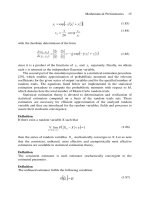
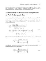
1.7 Design and Analysis with Composite Materials
In the theory of elasticity there are three sets of equations that are used [6]
Equilibrium
Stress-Strain (Constitutive Equations)
Strain-Displacement Relations/Compatibility equations
To illustrate these equations consider a prismatic bar as shown in Figure 1.24
below subjected to a load P,
34
In the above all but the stress-strain relations are independent of the material used
in the structure. Therefore, the equilibrium equations, the strain-displacement relations
and the compatibility equations are the same for an isotropic (where the material
properties are the same in every direction) structure as for an anisotropic (where
properties differ with direction) composite material structure. The compatibility
equations insure that all deflections are single valued and continuous.
The composite configuration is a key element in the selection of appropriate
constitutive equations for determining the stresses and deformations in a specific
structural member. Whether a composite material is unidirectional, cross-ply, angle ply,
woven, braided, or any other configuration, as well as the properties of the fibers and
matrix used, all determine the details of the constitutive equations.
Using these sets of equations, the design and analysis of composite structures can
be carried out. It is the purpose of this text to provide information, techniques of
solutions, some actual solutions and the knowledge to find many other solutions.
In design and analysis, there are four primary things to determine for any
structure:
1.
The location and magnitude of the maximum stresses.
Only by determining these maximum values can a comparison be made with the
strength of the composite material at that location in each principal direction to
determine if the structure is over-stressed (area will fail) or under-stressed (hence, too
heavy. In performing these calculations a few general concepts can be used.
A factor of safety (F.S.) is a number that is used and/or mandated to account for
unknown considerations such as unanticipated loads, material aberrations,
unanticipated uses, etc. A factor of safety could be as low as, for example, 1.5 for
fighter aircraft, and as high as 10 for elevator cables. The factor of safety is used to
relate the strength of the material to an allowable stress to which a structure is
designed and analyzed.
In this case the stress and strength are taken at the locations of maximum stress in
each principle direction.
Likewise, another often used measure of structural integrity is the margin of
safety (M.S.) defined by
In this equation the could be associated with the strength of the material or
the buckling stress (see below).
Generally if a structure has a positive margin of safety for the critical load
condition at the region of maximum stress it is considered to be structurally adequate.
35
2. The location and magnitude of maximum deflections.
This calculation indicates whether the structure is adequately stiff. Many
structures are stiffness critical; among these are aircraft wings, gyroscopes and the
chasses of automobiles. If the structure is too flexible or compliant, it cannot perform
its intended tasks.
3.
Determination of natural frequencies.
Almost every structure is subjected to dynamic loads. When a structure is
subjected to dynamic loads, whether cyclical or one time impact, every natural
frequency of the structure is excited. Therefore, it is important to determine the
important natural frequencies, and this will be discussed later.
If a cyclic loading occurs at one or more given frequencies it is important that no
natural frequency of the structure be close to these imposed frequencies. Otherwise,
the resonances that will occur will cause structural failure with time, or if failure does
not occur, fatigue problems will most likely occur.
4.
Determination of buckling loads.
When a structure is subject to compressive and/or shear loading, an elastic
instability can occur, termed buckling. Usually buckling is synonymous with
collapse and termination of the usefulness of the structure. Depending upon the
slenderness or frailty of the structure, the buckling (internal) stresses associated with
the buckling load can be a fraction of the strength of the material.
Therefore, in analyzing a structural design, an analyst must check out each of the
above four important criteria to insure that the structure is sound.
In designing a structure, one must therefore insure that the materials, stacking
sequences, thickness and configuration details (stress concentrations) are such that the
structure is adequate for the four important design considerations outlined above.
To complicate matters one must also consider temperature considerations in order
to use the mechanical properties at temperature extremes, consider any potential
corrosion effects, weathering, damage, moisture and other environmental effects, and if
the material is exposed to dynamic loads, consider high strain rate effects.
For composites, design and manufacturing are inextricably entwined. The
selection of a manufacturing process may be automatic, however, in many instances this
selection is based on available equipment and/or prior experience. This affects the type
of composite material used in the design. The geometry of the component, the number of
parts to be made, surface finish and dimensional stability can have a pronounced effect
on material selection and the resulting composite configuration.
36
1.8 References
1.
2.
3.
4.
5.
6.
7.
Composites Fabrication (2001) Vol. 17, No. 1, January, pp. 28-31.
Abrate, S. (2002) Resin Flow in Fiber Preforms, Applied Mechanics Reviews.
Harris, C.E., Starnes, Jr. J.H. and Shuart, M.J. (2001) An Assessment of the State-of-
the-Art in Design and Manufacturing of Large Composite Structures for
Aerospace Vehicles, NASA/TM-2001-210844, April.
Mouritz, A.P., Gellart, E., Burchill, P. and Challis, K. (2001)
Review of Advanced
Composite Structures for Naval Ships and Submarines, Composite Structures.
Critchfield, M.O., Morgan, S.L. and Potter, P.C. (1991) GRP Deckhouse
Development for Naval Ships,
Advances in Marine Structures, Elsevier, London,
pp. 372-391.
Sokolnikoff, I.S. (1956) Mathematical Theory of Elasticity, McGraw Hill Book Co.,
Inc., New York.
Bogdanovich, A.E. and Sierakowski, R.L. (1999) Composite Materials and
Structures: Science, Technology and Applications, Applied Mechanics Reviews,
Vol. 52, No. 12, Part 1, December.
1.9 Journals
The developments in the area of composite materials structures is developing so
rapidly that one can only attempt to keep current through extensive Journal readings.
However, a recent review article by Bogdanovich and Sierakowski [7] is suggested for
those interested in learning more about composite materials.
Below is a representative sample of Journals to read by which to keep current.
1.
2.
3.
4.
5.
6.
7.
8.
9.
AIAA Journal
Advanced Composites
Advanced Composites Bulletin
Advanced Composites Letters
Applied Composite Materials
Applied Mechanics Reviews
Cement & Concrete Composites
Composite Interfaces
Composite Material Technology
Composite Materials Science
Composite Structures
Composites
Composites & Adhesives
Composites Design & Application
Composites Fabrication
Composites Manufacturing
Composites Science and Technology
Composites Technology
Composites Technology & Research
10.
11.
12.
13.
14.
15.
16.
17.
18.
19.
37
20.
21.
22.
23.
24.
25.
26.
27.
28.
29.
30.
31.
32.
33.
34.
35.
36.
37.
38.
39.
40.
41.
42.
43.
44.
45.
46.
47.
48.
49.
50.
51.
52.
53,
54.
55.
Composites Technology Review
Composites. Part A: Applied Science and Manufacturing
Composites. Part B: Engineering
Computers & Structures
Experimental Mechanics
Fibre Science and Technology
High-Performance Composites
International Journal of Cement Composites & Lightweight Concrete
International Journal of Composite Structures
International Journal of Engineering Science
International Journal of Polymeric Materials
International Journal of Solids & Structures
Journal of Applied Mechanics
Journal of Applied Polymer Science
Journal of Composite Materials
Journal of Composite Technology & Research
Journal of Composites in Construction
Journal of Engineering Materials and Technology
Journal of Material Science
Journal of Materials Research
Journal of Mechanics and Physics of Solids
Journal of Reinforced Plastics and Composites
Journal of Sandwich Structures and Materials
Journal of Sound and Vibration
Journal of Testing and Evaluation
Journal of Thermoplastic Composite Materials
Mechanics of Composite Materials
Mechanics of Composite Materials and Structures
Mechanics of Materials
Polymer Composites
Polymer Engineering and Science
Polymers & Polymer Composites
Reinforced Plastics
SAMPE Journal
SAMPE Quarterly
Shock and Vibration Digest
1.10 Problems
Select an area of composite materials science and technology that interests you, and
scan several of the above journals for papers written in the last two years. Read at
least eight of them and provide a bibliography of these papers.
Select three papers from the above that you feel are the best, describe what the
authors did, how they did it and tell why you consider these papers to be the best.
1.
2.
38
3.
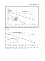
From the materials listed in Table 2.2, construct a graph in which the ordinate is the
ratio of strength in the fiber direction to density and the abscissa is the ratio
of modulus of elasticity in the fiber direction to density Plot a point on the
graph for each material.
a.
b.
c.
d.
Which material will be the lightest to use in a strength critical structure?
Which material will be the lightest to use in a stiffness critical structure?
Which material would be the heaviest to use in a strength critical structure?
Which material would be the heaviest to use in a stiffness critical structure?
CHAPTER 2
Anisotropic Elasticity and Composite Laminate Theory
When research began on composite materials, as described in Chapter 1,
definitions and nomenclature were developed that formed a vocabulary and approach
specialized to composite materials structures. To systematically develop a theory for
composite materials structures, one should begin with the following derivations [1-3]
*
.
2.1 Introduction
An isotropic material is one that has identical mechanical, physical, thermal and
electrical properties in every direction. Isotropic materials involve only four elastic
constants, the modulus of elasticity, E, the shear modulus, G, the bulk modulus K and
Poisson’s ratio, However, only two are independent, and the following relationships
exist:
Most engineers and material scientists are well schooled in the behavior and design of
isotropic materials, which include the family of most metals and pure polymers. The
rapidly increasing use of anisotropic materials such as composite materials has resulted in
a materials revolution and requires a new knowledge base of anisotropic material
behavior.
Before understanding the physical behavior of composite material structures and
before being able to quantitatively determine the stresses, strains, deformations, natural
frequencies, and buckling loads in such structures, a clear understanding of anisotropic
elasticity is necessary. In general, isotropic materials are mathematical approximations to
the true situation. For instance, in polycrystalline metals, the structure is usually made up
of numerous anisotropic grains, wherein macroscopic isotropy exists in a statistical sense
only because the anisotropic individual grains are randomly oriented. However, the same
materials could be macroscopically anisotropic due to cold working, forging or spinning
during a fabrication process. Other materials such as wood, human and animal bone, and
all fiber reinforced materials are anisotropic.
Fiber reinforced composite materials are unique in application because the use of
long fibers results in a material which has a higher strength-to-density ratio and/or
stiffness-to-density ratio than any other material system at moderate temperature, and
there exists the opportunity to uniquely tailor the fiber orientations to a given geometry,
Number in brackets refers to the number of the reference in Section 2.11.
*
40
applied load and environment. For short fiber composites, used mainly in high
production, low cost systems, the use of fibers makes the composites competitive and
superior to plastic and metal alternatives. Finally, the use of two or more kinds of
dissimilar fibers within one matrix is termed a hybrid composite, where one fiber is
stronger or stiffer while the other fiber is less expensive but desirable for less critical
locations in an overall structural component. Other examples of a hybrid composite
involve stronger and stiffer (but more brittle) fibers that are protected by outer plys of a
tougher fiber composite to protect the composite from impact and other deleterious
effects. Therefore through the use of composite materials, the engineer is not merely a
materials selector, but is also a materials designer.
For small deflections, the linear elastic analysis of anisotropic composite
material structures requires the use of the equilibrium equations, strain-displacement
relations, and compatibility equations, which remain the same whether the structure is
composed of an isotropic material or an anisotropic composite material. However, it is
very necessary to drastically alter the stress-strain relations, also called the constitutive
relations, to account for the anisotropy of the composite material structure.
A quantitative understanding of the virtues of using composite materials in a
structure is found through deriving systematically the anisotropic elasticity tensor matrix,
as discussed in Section 2.2.
2.2 Derivation of the Anisotropic Elastic Stiffness and Compliance Matrices
Consider an elastic solid body of any general shape, and assume it is composed of
an infinity of material points within it. In order to deal with a continuum, one also
assumes that the material points are infinitely large compared to the molecular lattice
spacing of the particular material. If one assigns a Cartesian reference frame to the
elastic body shown in Figure 2.1, one then calls this rectangular parallelepiped material
point a control element or control volume of dimension dx, dy and dz in a Cartesian
coordinate system.
41
On the surface of the control element there can exist both normal stresses (those
perpendicular to the plane of the face) and shear stresses (those parallel to the plane of the
face). On any one face the three mutually orthogonal stress components comprise a
vector, which is called a surface traction.
It is important to note the sign convention and the meaning of the subscripts of
these surface stresses. For a stress component on a face whose outward normal is in the
direction of a positive axis, the stress component is positive when it is in the direction of
a positive axis. Also, when a stress component is on a face whose outward normal is in
the direction of a negative axis, the stress component is positive when it is in the direction
of a negative axis. This can be seen clearly in Figure 2.1.
The first subscript of any stress component on any face of the control element
signifies the axis to which the outward normal of the face is parallel; the second subscript
refers to the axis to which that stress component is parallel. Again, see Figure 2.1.
The strains occurring in an elastic body have the same subscripts as the stress
components but are of two types. Dilatational or extensional strains are denoted by
where and are a measure of the change in dimension of the control volume in
the subscripted direction due to normal stresses, acting on the control volume. Shear
strains are proportional to the change in angles of the control volume from 90°,
changing the rectangular control volume into a parallelogram due to the shear stresses,
For example, looking at the control volume plane shown in Figure 2.2
below, shear stresses and cause the square control element with 90° corner angles
to become a parallelogram with the corner angle as shown. Here, the change in angle
is
The shear strain a tensor quantity is defined by
Similarly, and
Having defined all of the elastic stress and strain tensor components, the stress-
strain relations are now used to derive the anisotropic stiffness and compliance matrices.
The following derivation of the stress-strain relations for an anisotropic material
parallels the derivation of Sokolnikoff [1], Vinson and Chou [2], and Vinson [3].
Although the derivation is very formal mathematically to the reader who is primarily
interested with the end result, the systematic derivation does provide confidence in the
extended use of the results.
From knowledge of basic strength of materials [4], both the stresses, and the
strains are second order tensor quantities, where in three dimensional space they have
42
components. They are equated by means of the fourth order elasticity tensor,
which therefore has components, with the resulting constitutive equation:
where i, j, k and l assume values of 1, 2, 3 or x, y, z in a Cartesian coordinate system.
Fortunately, there is no actual material that has eighty-one elastic constants. Both the
stress and strain tensors are symmetric, i.e., and and therefore the
following shorthand notation may be used:
At the outset it is noted that and which are quantities widely used in
composite analyses, are not tensor quantities and therefore do not transform from one set
of axes to another by affine transformation relationships. Care must also be taken
regarding whether or not to use the factor of "two" when using shear strain relations.
Using Equation (2.5), Equation (2.4) can be written:
43
It should be noted that the contracted quantities are also not tensor quantities,
and therefore cannot be transformed as such.
Hence by the symmetry in the stress and strain tensors the elasticity tensor
immediately reduces to the 36 components shown by Equation (2.6). In addition, if a
strain energy density function, W, exists [1 through 4], i.e.,
in such a way that
then the independent components of are reduced to 21 elastic constants, since
and now it can be written
Next, to simplify the general mathematical anisotropy to the cases of very
practical importance, consider the Cartesian coordinate system only. (However, the
results are applicable to any curvilinear orthogonal coordinate system of which there are
twelve, some of which are spherical, cylindrical, elliptical, etc.).
First, consider an elastic body whose properties are symmetric with respect to the
plane. The resulting symmetry can be expressed by the fact that the
discussed above must be invariant under the transformation and
shown in Figure 2.3.