The Materials Science of Coatings and Substrates Part 9 docx
Bạn đang xem bản rút gọn của tài liệu. Xem và tải ngay bản đầy đủ của tài liệu tại đây (966.49 KB, 25 trang )
Additives
201
202
Electrodeposition
Figure
2:
pyrophosphate copper deposits. Adapted from reference
22.
Effect
of
plating parameters on the tensile properties
of
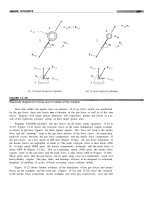
Figure
3:
Tensile properties and morphology
of
annealed pyrophosphate
copper deposits versus additive concentration. From reference
28.
Reprinted with permission of
The
Journal
of
Applied
Electrochemistry.
Additives
203
levels
(3.0
to
4.0
cm3M3) the ductility again decreases, presumably because
of
inclusion of excessive additive in the deposit (Fig.
3j).
INFLUENCE ON LEVELING
Normal electrodeposition accentuates roughness by putting more
deposit on the peaks than in the valleys of a plated surface since the current
density is highest at the peaks because the electric field strength is greatest
in
this
region.
In
order to produce a smooth and shiny surface, more metal
has to
be
deposited in the valleys than on the peaks, which is the opposite
of the normal effect. The function of certain organic compounds is to
produce
this
leveling in plating solutions. Leveling agents are adsorbed
preferentially on the peaks of the substrate and inhibit deposition. This
inhibiting power is destroyed on the surface by a chemical reaction which
releases it, setting up a concentration gradient close to the surface.
An
example is coumarin which is used in the deposition of nickel. It adsorbs
on depositing nickel by the formation of two carbon-nickel bonds and
inhibits nickel deposition probably by a simple blocking action. It is
removed from the surface and destroyed by reduction with the main product
which is melilotic acid
(29).
Radioactive tracer studies have been particularly effective for
studying the behavior of addition agents. Additives such as sodium allyl
sulfonate, labeled by the reaction between allyl bromide and
S
labeled
sodium sulfite were used in Watts type nickel solutions
(30).
Grooved brass
cathodes were plated with nickel. These substrates had been passivated
prior to plating
so
that the foil could be stripped for counting purposes
(Figure
4).
Results of the counting experiments (Table 2) show that more
activity was deposited on the peaks than
in
the recesses. Work of
this
type
supports the theory that the addition agent is preferentially adsorbed on the
high
points of
an
irregular surface where it acts as
an
insulator.
This
inhibits deposition of metal and diverts current to recessed areas
(30).
Radioactive tracer techniques, used
in
Watts nickel solutions, have
revealed that a number of mechanisms are feasible, either diffusion and
adsorption, or cathodic reduction (31). When two or more compounds were
added, the mechanism of incorporation became more complex. Other work
on use of radioactive tracer studies
with
additives can
be
found
in
references
A
practical example of the influence of additives
on
leveling is
shown
in Figure
5
(37).
A
proprietary additive in a copper sulfate solution
reduced surface roughness as much
as
70
percent with a deposit as thin as
20
um
(0.
8
mil). Besides producing deposits which level the hills and
valleys on a substrate, levelers also inhibit the formation of asperities such
32-36.
204
Electrodeposition
Figure
4:
Cathode
foil
and shield for radiotracer studies.
Grooved brass
cathodes were plated with nickel which was then passivated to permit
stripping of subsequent foils. Counting shield had grooves that limited
betas activating the counter
to
those from either one peak
or
one valley.
Adapted from reference
30.
Figure
5:
Leveling power
of
bright copper deposited
in
copper sulfate
solution
containing a proprietary additive. Adapted
from
reference
37.
Additives
205
Table
2:
Lead
Slit Counting Rates for Foils Shown in Figure
4*
Foil
A
Topt
Foil
B
Top
eejak
125
115
115
143
21 3
226
224
125
106
55
79
Recess
94
72
53
63
80
1 63
212
65
64
55
57
Foil
A
Bottom
eaiak
Recess
42
27
33
33
76 53
47 81
177 91
163 160
94
97
147 34
43
28
59
45
58
Foil B
Bottom
Obverse of Obverse of Obverse of Obverse
of
m
receSS
Qeak
leceSS
248
198
152
120
207
254
227
150
146
181
242
143
103
1 33
112
102
113
163
146
129
158
129
145
133
134
154
135
190
21 2
176
163
144
102
58
77
84
65
100
128
126
101
82
80
Counting was
left
to
right
on
the top of
the
foil and right
to
left
on
the bottom,
so
that the values
in
the columns are matched.
t
"Top" refers
to
the side next
to
the
solution during plating,
"bottom"
to
the side next
to
the
cathode.
*
From Reference
30.
206
Electrodeposition
as nodules. This increases the stability of the deposition process,
particularly for thick coatings (29).
INFLUENCE ON BRIGHTENING
A bright deposit is one that has a
high
degree of specular reflection
(e.g., a mirror), in the as-plated condition. Although brightening and
leveling are closely related, many solutions capable of producing bright
deposits have no leveling ability (38).
If
the substrate is bright prior to
plating, almost any deposit plated on
it
will
be
bright if
it
is
thin
enough.
However, a truly bright deposit will
be
bright over a matte substrate and it
will remain bright even when
it
is thick enough
to
hide the substrate
completely. Plating solutions without addition agents seldom or never
produce bright deposits.
There is a direct relationship between brightness and surface
structure of electrodeposits
as
shown in Figure
6
(39). The measure of
smoothness used in
this
example is the fraction of the surface area which
does not deviate from a plane by more than
0.
15 pm, which is of the order
of the wavelength
of
visible light. This value was chosen because
it
has
been found that with specularly bright nickel, there are no hills higher or
valleys deeper than
0.
15 pm (39,40).
Figure
6:
Relationship between quantity of reflected light (brightness) and
fractidn of area with roughness less
than
0.15
um.
Adapted
from
reference
40.
Additives
207
CLASSIFICATION AND
TYPES
OF
ADDITIVES
Additives can be classified into four major categories: 1-grain
refiners, 2-dendrite and roughness inhibitors, 3-leveling agents, and
4-wetting agents or surfactants (3). Typical
grain
refiners are cobalt or
nickel codeposited
in
trace
amounts
in gold deposits. Dendrite and
roughness inhibitors adsorb
on
the
surface
and
cover
it with
a
thin
layer
which serves
to
inhibit the
growth
of
dendrite precursors.
This
category
includes both organic and inorganic materials with the latter typically being
more stable. Leveling agents, such
as
coumarin or butynediol in nickel
solutions, improve the throwing power
of
the plating solution mostly by
increasing the
slope
of
the activation potential curve. The prevention
of
pits
or pores in the deposit is the main purpose
of
wetting agents or surfactants
(3).
Metals differ in their susceptibility
to
the effect of additives, and the
order of this susceptibility is roughly the same
as
the order
of
their melting
points, hardness and strength;
it
increases in the order
Pb,
Sn, Ag, Cd,
Zn,
Cu, Fe, Ni (41). Thousands of compounds are known that brighten nickel
deposits from the sulfate-chloride solution, while
it
is
only
fairly recently
that ways of brightening tin deposits from acid solutions have been
developed. The progression in the series corresponds to:
1)
the increasing
tendency
of
metal ions
to
form complexes and
2)
to
increasing activation
polarization from simple ions.
This
is in the reverse order
to
the
overvoltages observed in the evolution
of
hydrogen on metal cathodes.
Lyons suggests that: "An atom which is capable of interacting strongly with
other atoms of the same or other kinds tends to form
a
strong crystal lattice
with
a
relatively high melting point, to coordinate strongly with ligands, to
decoordinate water slowly, and
to
catalyze conversion of atomic to
molecular hydrogen" (41).
Additives are often high molecular weight organic compounds or
colloids since small ions or molecules are generally not very effective (42).
This is shown in Table
3
which relates minimum concentration of organic
compounds required
to
impart appreciable brightness to nickel deposits (43).
The size of the molecule can also influence the stress
in
the deposit.
Coumarin, which
is
a
small molecule compared to phenosafranine (Figure
7)
reduces macrostress in nickel deposits, whereas, phenosafranine increases
tensile macrostress
(44).
An open discussion of the components of brightener systems is
difficult because many of these systems are proprietary. Suppliers guard
their formulations from distribution simply because the brightener market
is
so
competitive. However, there are numerous technical publications
detailing many of the additives commonly used. A listing
of
the materials
that have been used
as
additives in plating solutions culled from
the
open
208
Electrodeposition
Table
5:
Relationship Between Molecular Size and Minimum
Concentration
of
Organic Compound Required
to
Cause
Brightening in Nickel Plating*
Avg. Min. Conc.
to
Brighten
-
ExamDle
Very large
Magenta dye
0.000057
Bicyclic Saccharin
o.oooa5
Monocyclic Furfural
0.008
Short
chain alkyl
compounds Acryonitrile
0.003
*
From
Reference
43.
literature would
be
monumental and will not
be
attempted here. However,
some limited examples will
be
presented in the material that follows.
Cadmium
-
Glue was used in solutions for electrowinning of
cadmium from around
1910 (45).
The
first
bright cadmium plating solution
was
introduced in
1925
and consisted
of
a cyanide solution plus a caustic
solution
of
proteins
(14).
Some
of the addition agents that have been used
in
the
ensuing years for cadmium include sulphonated castor oil (Turkey
Red Oil), aromatic aldehydes, and inorganic salts such
as
nickel
or
cobalt
compounds
(46).
Copper
-
Some of
the
materials that have been used with acid
copper include glue, dextrose, phenolsulfonic acid, molasses and thiourea.
Many
of
the present day commercially available brighteners contain
three
components designated
as
carrier, leveler and brightener. Reid suggests
that: "Carriers are typically polyalkylene glycol type polymers with a
molecular weight around
2000,
levelers are typically alkane surfactants
containing sulfonic acid and amine or amide functionalities, and brighteners
are typically propane sulfonic acids which are derivatized with surface
active groups containing pendant sulfur atoms"
(47).
Additives for cyanide copper systems include compounds having
active sulfur groups and/or containing metalloids such
as
selenium
or
tellurium. Other agents that have worked are organic amines or their
reaction products with active sulfur containing compounds; inorganic
compounds containing such metals
as
selenium, tellurium, lead, thallium,
antimony, arsenic; and organic nitrogen and sulfur heterocyclic compounds
(48).
An extensive listing
of
additives used in acid and cyanide copper
prior to
1959
can
be
found in reference
48.
Additives
209
Figure
7:
Schematic representation of coumarin
and
phenosafranine
molecules drawn approximately to scale. From reference
44.
Reprinted
with permission of
The
Electrochemical
Soc.
Gold
-
There are three principal types
of
additives associated with
high purity gold electrolytes: complexing agents, grain refiners, and
hardening agents
(49).
Complexing agents such
as
pyrophosphate ion,
organophosphorus compounds and
pol
yphosphates are added
to
reduce the
activity
of
metallic impurities in the solution by forming stable complexes
and hence minimizing codeposition. Organic chelating agents such
as
EDTA
and related compounds are
also
used. Relatively small amounts
of
base metals are used for providing grain refinement. These additives also
210
Electrodeposition
provide smoothing and semi-brightening
of
the deposit,while not being
codeposited to a significant extent.
In
neutral solutions, arsenic and
thallium have been used. Some additives such as alums and hydrazine
sulfate have been claimed to harden the electrodeposit without being
codeposited
(49).
Use
of
heavy metal ions in trace quantities (parts
per
million) in
gold electroplating solutions, induces a marked cathodic depolarization
which extends the range
of
current
densiti2s over which smooth,
fine
grained deposits can
be
obtained
(SO-5%.
In
slightly alkaline phosphate
electrolytes the most effective additives comprise the family of elements Hg,
T1, Pb and Bi, which lie immediately adjacent
to
gold in the periodic table.
They exhibit a strong tendency
to
form
an adsorbed monolayer on gold and
platinum electrodes.
This
is done at potentials positive
to
those at which
their cathodic deposition
as
bulk metals would begin, i.e. at underpotentials
(52).
Deposits obtained with these additives have a very fine and highly
uniform
grain size
(51).
The various heavy metal ions have a brightening
effectiveness which is in the order
"I
>
Pb
>
Bi
>
Hg.
This
is
the inverse
order of their electron work functions (the amount of energy required to lift
an
electron
out
of a lattice). The postulated mechanism for
this
performance
is
that the elements form an adsorbed monolayer on the surface of the gold.
This
lowers its work function and thereby lowers its deposition potential
so
that deposition then occurs at underpotentials (52). An excellent review on
additives for gold plating systems can
be
found in reference 53.
Lead
-
Common additives for deposition
of
lead from fluoborate
solutions include peptone and resorcinol
(54).
For
plating strip, which
requires high current densities
of
loo0
amp/ft2
or
greater, hydroquinone was
the best additive out
of
230 compounds evaluated on the basis
of
performance, stability, cost and lack
of
industrial hazard
(55).
Compounds
which provided grain refinement and lo00 amp/ft2
or
better,limiting current
density were the following structural groups listed in decreasing order of
effectiveness: aliphatic compounds, benzene derivatives, naphthalene
derivatives, anthraquinone derivatives and heterocyclic compounds.
Nickel
-
The key to modem bright nickel plating was the
discovery of combining an organic "carrier" brightener with an auxiliary
compound to produce brightness and leveling
(45).
These are referred
to
as Class
1
and Class
I1
brighteners and materials of each
type
are listed in
Table
4.
Brighteners of the first class have two functions: 1-provide bright
deposits over a bright substrate and 2-permit the second class brighteners to
be present over an acceptably wide range of concentrations. Brighteners of
the second class are used to build mirror-like lustre. However, most of
these lead to excessive brittleness and stress in deposits in
the
absence of
brighteners of the first class
(56).
Comparisons of the two brightener
Additives
21
1
'r
21
2
Electrodeposition
Table
5:
Comparison
of
Carriers and Brighteners Used
In
Nickel
Plating Solutions*
Carriers (Class
U
Rriahteners (Class
lu
Bright or cloudy deposits,
unable to provide high lustre
with continued plating
Brilliant leveling and
increasing lustre
Sulfur
(0.03%)
occluded in
deposit when Class
I
compounds
are used without Class
II
compounds
Introduces carbon in
the deposit
No
critical upper concentra-
tion, used in high concentra-
tions(1-I0 gll). Cathode poten-
tial increases
15-45
mv in low
concentrations, then very little
change with further additions.
Cathode potential continues
to
increase sharply with
increases in concentration
Do
not cause cracking or
peeling.
Reduce stress, can result in
compressive stress. Lessen
ductility slightly.
Deposits crack and peel when
the cathode potential increase
exceeds approximately
30
mv
Have a very deleterious effect
on properties, producing brittle,
highly stressed deposits.
*
From references
43
and
59.
classes are provided
in
Table
5.
For
more detail on nickel plating
brighteners,
see
references
43, 45, 46, 56-59
and the Corrosion chapter in
this
book.
Silver
-
Present silver solutions closely resemble the one described
in the first patent over
140
years ago
(8).
Carbon disulfide and thiosulfate
have been the most widely
used
addition agents over the years. Many other
materials have been proposed, including
gums,
sugars, unsaturated alcohols,
sulfonated aliphatic acids, xanothogenates, Turkey Red Oil, Rhodamine Red
and compounds of antimony
and
bismuth
(4660).
Most of these agents are
sulfur bearing organic compounds
or
reaction products of sulfur and organic
compounds
(60).
Additives
213
Tin
-
Similar to most acid solutions, deposits of
tin
from acid
solutions containing no additives are crystalline and nonadherent. The
development
of
smooth deposits free from treeing resulted from years
of
extensive research on a long list of addition agents. Mose (61) reviewed
the
types
of addition agents reported
in
the literature
to
about 1960 and
Macintosh
(62) and Dennis (46) to
the
early 1970’s.
Tin-Lead
-
Some of the common additives are glue, resorcinol,
nicotine, peptone, beta-naphthol, biphenyl sulfones and ethoxy ethers (63).
Coatings
of
terne alloy containing up to 14% tin have been electrodeposited
from fluoborate solutions containing hydroquinone
as
the
addition agent
(64).
Zinc
-
Typical additives from research in the early 1900’s
for
acid
zinc plating included dextrose, dextrin, glucose, beta naphthol, vegetable
gums, gelatin, brewers yeast and licorice (15.65, 66). An excellent review
of the early history
of
additives for zinc plating as well
as
development of
brighteners for the various zinc systems has been provided by Geduld (15).
Two early zinc plating additives which did not amount to much
commercially but which paved the way for future developments were
naphthalene disulfonate
(67)
and pyridine (68). These opened up
an
area
of
investigation into the use of heterocyclic organic additives in zinc plating
which eventually led
to
the primary constituents of many brighteners used
in
the field today, especially in bright cyanide zinc plating (15).
Compounds used as brighteners in zinc cyanide solutions include
aromatic aldehydes such as anisaldehyde, polyvinyl alcohol, glue, gelatin,
and sodium sulfide (46). Crotty reviewed the patent literature and pieced
together skeletal brightener formulations to illustrate the functional
properties of a system, demonstrating the roles of carriers and brighteners
in alkaline cyanide, noncyanide and acid chloride systems (69). Earlier,
DaFonte provided detailed discussion
of
additive chemistry for zinc plating
systems
(70).
Zinc plating additives can
be
broken down
into
three
categories: carriers, brighteners and purifiers. Carriers provide
a
smooth
deposit and also prevent the formation
of
dendrites. The brighteners form
a
truly
bright deposit by adding clarity
to
the smoky deposit provided by the
carrier. Purifiers are used to remove the last traces
of
smokiness in the
deposit.
This
smokiness might result from impurities in chemicals from the
plating solution
or
from metals that are present in zinc anodes (69).
MECHANISMS
Additives act as grain refiners
and
levelers because of their effects
on 1) electrode kinetics and 2) the structure of the elecuical double layer at
the plating surface (71). Since additives are typically present in extremely
214
Electrodeposition
small concentrations, their transport towards
the
electrode is nearly always
under diffusion control and, therefore, quite sensitive to flow variations
(3).
The effects of additives
are
often manifested by changes in the polarization
characteristics of the cathode. Many are thought
to
function by adsorption
on the substrate
or
by forming complexes with the metal.
This
results in
development of a cathodic overpotential which is maintained at a level
which allows the production of smooth, non-dendritic plates having the
desired grain structure
(71).
An
example is bright nickel deposition which
is
accompanied by a cathode potential increase (polarization) of the order
of
20
mv,
or
more as shown in Figure
8 (43).
Figure
8:
Cathode potentialconcentration curve for
1
naphthylamine
4.8
disulfonic
acid. The
first
sign of brightening of the nickel deposit is
indicated by
an
arrow.
Adapted
from
reference
43.
Numerous mechanisms have been suggested to explain behavior
of
additives:
1)
blocking the surface,
2)
changes in Helmholtz potential,
3)
complex formation including induced adsorption and ion bridging,
4)
ion
pairing,
5)
changes in interfacial tension and filming of the electrode,
6)
hydrogen evolution effects, 7) hydrogen absorption,
8)
anomalous
codeposition, and
9)
the effect
on
intermediates. These are discussed in
detail in a comprehensive review by Franklin (72). Additional excellent
coverage
on
mechanisms of levelling and brightening of addition agents can
be found in the recent paper by Oniciu and Muresan (72a).
Additives
215
DECOMPOSITION
OF
ADDITION AGENTS
Addition agents are generally consumed
in
the deposition process.
For example, in the case of nickel they may be decomposed and the
products in part incorporated in the deposit (sulfur, carbon,
or
both) or
released back into the electrolyte.
At
a
pH of
4,
approximately
90%
of the
coumarin consumed at the cathode is reduced to melilotic acid and
incorporated in the deposit
(46).
Radiotracer work has shown virtually
complete molecules of melilotic acid, of approximately
lOA
incorporated in
nickel deposits plated from solutions containing coumarin
(31).
Figure
9
relates labeled sulfur content of a nickel deposit to
concentration of saccharin in the solution and is similar in shape to that
obtained with carbon when coumarin is used in nickel solutions.
Breakdown products of additives can affect internal stress in the deposit.
For example, eight decomposition products are possible with saccharin
(benzoic acid sulfimide) and these are listed
in
Figure
10.
Of
these eight
products, it has been shown that o-toluene sulfonamide and benzamide are
found in Watts nickel solutions when saccharin
is
used
(73).
Figure
11
shows the build up of these two decomposition products as
a
function
of
solution electrolysis time and their influence on stress in the deposit.
In
the
case of these products, when their concentration gets too high, they are
removed by treatment with activated carbon.
Figure
9:
Relationship between bulk concentration
of
saccharin
in
a
Watts
nickel plating solution and
sulfur
content of deposit. Plating conditions:
temperature
55°C
pH
4.4
and current density
4
A/dmz.
Adapted from
reference
46.
216
Electrodeposition
Figure
10:
Possibilities
for
the decomposition
of
benzoic acid sulfimide
(saccharin). From reference
73.
Reprinted with permission of The
American Electroplaters
&
Surface Finishers
Soc.
Figure
11:
Decomposition of benzoic acid sulfimide (saccharin) during
electrolysis and its influence on stress. From reference
73.
Adapted from
reference
73.
Additives
217
CONTROL AND ANALYSIS
OF
ADDITIVES
Lack of control of plating solutions is a major problem which leads
to
reduced reliability and increased costs for plated parts. One reason that
progress
in
this area has
been
slow is the difficulty
of
performing
quantitative analysis on the additives,
often
a mixture
of
two
or
more
compounds (not to mention the numerous additive breakdown products that
can
accrue with time) in the ppm and ppb ranges
in
the presence
of
high
concentrations
of
electrolytes (74). Techniques that
are
available include
the Hull cell, bent cathode, chromatography, a variety
of
electroanalytical
meth&,impedance probes and spectrophotometry.
HULL CELL
A number
of
researchers have stated that the Hull Cell has probably
contributed more
to
the advancement
of
electroplating than any other tool
(15,75) and this
is
likely
true.
Jackson and Swalheim contend that "a plater
without a Hull Cell is like an electrician without a voltmeter" (76).
It
is a
simple, easy test
to
run and does not require advanced technical training for
interpretation of results. With this test one can determine plating
characteristics over at least a tenfold change in current density range.
Although
it
is not nearly as exotic and complex
as
many
of
the other
analytical tools discussed in this section the fact that this tool, first
demonstrated in
1939
(77) is still viable shows that
it
has weathered the test
of
time (78).
The Hull Cell is a trapezoidal
box
of
non-conducting material with
one side at a 37.5 degree angle (Figure 12).
An
anode
is
laid against the
right angle side and a cathode panel is laid against
the
sloping side. When
a current is passed through the solution sample contained in the cell, the
current density along the sloping cathode varies in a
known
manner. In this
way the character of the deposit at a range
of
current densities is determined
in one experiment. Current used in the cell varies from
1
to
3
amps, and
time from 2 to
10
minutes, depending
on
the type of solution being tested.
Special rulers
or
scales are available that are marked to show specific
current densities
on
a plated Hull Cell panel depending
on
the amperage
used (78) (Figure
13).
The standard Hull Cell is 267 ml capacity, a volume
selected
in
premetric days because 2
grams
of
material added to the cell
corresponds to a
1.0
odgal addition to the main plating solution. Today
Hull Cells are available in a variety
of
sizes including
500
ml and
1
liter to
fulfill needs
of
those working in the metric system.
A Hull cell panel gives more information than the useful plating
range. It reveals a pattern of bright, semi-bright, dull, burned, pitted and
218
Electrodeposition
cracked areas that typically describe results of a specific test. Figure 14
shows one technique for recording data from Hull Cell panels
(79).
Modifications
to
the Hull Cell have appeared including a cell with
holes
in
the two parallel sides to permit solution circulation while
the
cell
is immersed in the actual plating tank under evaluation
(80).
.
This cell can
be
operated for long periods
of
time without temperature fluctuation.
A
more recent modification is the Gomall Cell (Figure
15)
which is used for
testing solutions for the printed wiring board industry
(81).
This version
allows for plating of samples with drilled holes and provides accurate
Additives
219
Figure
13:
Hull cell ruler. Adapted
from
reference
78.
Note:
This
is not
to
scale
sine
it
was reduced
for
printing purposes.
Figure
14:
Code
defining
the
surface
appearance
of
a
Hull
cell planel.
From
reference
79.
Reprinted with permission of Metal
Finishing.
220
Electrodeposition
Figure
15:
Gomall cell for studying surface-to-hole ratios for printed
wiring boards. Adapted from reference
81.
surface-to-hole ratios
as
a function of current density. For more detail on
the Hull Cell and its operation besides
the
references already cited, the
book
by Nohse
(82)
is recommended.
However, while the Hull Cell has been adequate in the past, the
increasing demand for process automation and the increasing complexity
of
parts makes the need for quantitative control
of
organic additives more
important. The Hull Cell can
be
misleading when used
to
evaluate high
speed processes because parameters related to solution flow, solution
geometry and current distribution are not always reproduced
(83).
Also,
new additives required for high current density operation and other advances
will have
to
function under much more severe constraints than those
presently in use and will require more sophisticated control than attainable
with the Hull Cell.
BENT
CATHODE
Another test that can
be
used
to
monitor some additives is the bent
cathode. Shown in Figure
16,
a
panel bent in this configuration and plated
in either a beaker in the laboratory or in the actual production tank can
provide information on leveling, burning and striations, roughness, low
Additives
221
Figure
16:
Bent cattiode test panel. Adapted from reference
84.
current density problems and pitting. Inspection is performed after opening
the bottom portion of the panel. Details on operation of
this
test and its
value for controlling acid copper sulfate solutions can
be
found in reference
84.
CHROMATOGRAPHY
Chromatographic techniques have been finding increased usage in
monitoring of plating solutions
(85).
Their main attraction is the ability to
quantitate simultaneously low concentrations
of
several inorganic and
organic solution constituents
in
one analytical
run.
With chromatography,
the usage of two terms-High Performance Liquid Chromatography (HPLC)
and Ion Chromatography (IC) has caused some confusion.
For
this reason
a more general term, Liquid Chromatography (LC)
is
now preferred
(85).
A
detailed explanation
of
modern
LC
methods can
be
found in reference
86
and applications of LC
for
analysis of electroplating additives in Table
6.
Liquid chromatography is
shown
schematically in Figure
17.
It
consists
of
four modes:
1)
a sample delivery mode
-
this
includes a
high-pressure analytical pump and a sample injection valve;
2)
a separation
mode
-
this
includes one
of
a variety
of
analytical separator columns;
3)
a detection mode
-
this includes one
of
a variety of detectors; and
4)
a
data reduction mode
-
this can range from a simple
X-Y
strip chart
recorder to a personal computer system
(87).
222
Electrodeposition
Table
6:
Plating Solution Additives Analyzed by Various Techniques
Solution
Copper
Acid sulfate
Pyrophosphate
Electroless
Gold
Acid cyanide
Lead
Fluoborate
Perchlorate
Additive
Proprietary
"
Thiocarbamoyl-thio- alkane
sulfonates
Mercaptopropane sulfonic acid
Thiourea
Polyethylene glycol
Polyether sulfides
Sulfoniumalkane sulfonates
N,N-dimethylaniline
2-mercaptobenzothiazole
Proprietary
Dimercaptothiadiazoles
Adenine, guanine. saccharin,
coumarin
Mercaptobenzothiazole
Co
and Ni hardeners
Lignin sulfonate
Rhodamine-B
Analysis
Reference
Method'
v
C
I
v
C
P
I
I
v
v
I
I
v
v
v
v
P
P
v
v
104,108,109,1
IO,
11 1,112
47,85,87,99,113-
115
105
116
117
118
74,119
120
96
97
74
74
121
92-95,98,101
,I
02
122
83,123
118
1
24
71
125
(continued)
Additives
223
Table
6:
(continued)
Nickel Proprietary
Pyridine derivatives
Saccharin
Acetylenic alcohols,
aromatic sulfonamides
Wetting agents
0-be nzalde hyd
e,
sulfonic acid
2 butyne 1,4 diol
Rhodamine B,sodium
saccharin
Sodium benzene-
sulfonate
Sodium lauryl sulfate
Palladium Hydroquinone
Silver Propargyl alcoho1,2,5-
Cyanide dimethyl-2,5 hexane diol
Tin Proprietary
Tin-lead Proprietary
Fluohrate Resorcinol
Zinc Benzoic acid,anisal-
dehyde,vanillin, and
many other compounds
0-chlorobenzalde hyde
C
P
v,s
P
v,s
C
P
C
85
129,130
107
126
107
73,85,88.127,128
118
130
C 128
P 118
C
85
I
131
V
106
I
131
C 85,128
P 118
I
132
C 88,133,134
P 136
V,P 135,110
C 127
C
69,130
P 90,118
V-voltammetry
C-chromatography
P-polarography
I-impedance
S=spectrophotomet
ry
224
Electrodeposition
Figure
17:
Schematic
of
an
HPLC
system.
Adapted from reference
87.
As
shown in Table
6,
chromatographic techniques have been used
to analyze additives in acid copper, nickel, tin, tin-lead and zinc plating
solutions. Figure
18
shows an
HPLC
chromatogram
of
some organic
brighteners cited in the literature for zinc plating
(69).
The breakdown
products of saccharin discussed earlier and shown in Figures
10
and
11
were determined by chromatography.
A
recent innovation includes the use of scanning
UV
detectors in
the chromatographic system. Unlike conventional single wavelength two
dimensional chromatograms, the recordings produced by scanning detectors
are three dimensional. These
3-D
chromatographic plots facilitate the
Additives
225
Figure
18:
HPLC
chromatogram of sonie organic briglitetiers citcd
in
the
literature for
zinc
plating. From reference
69.
Repritlted with
permission
of
the
American Electroplaters
&
Surface Finishers
SOC.
identification
of
unknown peaks and help
to
improve knowledge
of
chemical
reactions responsible for the properties of deposits. Figures
19
and
20
show
respectively a conventional chromatogram and the corresponding
3-D
plot
obtained. The peaks
1,2,3
and
4
came from one additive solution and the
two late eluting peaks
5
and
6
were attributed
to
a replenisher solution.
Peak
2
originating from the replenisher additive could
be
identified as
phenol which was a degradation product from the organic additive
(88).