The Welding of Aluminum & Its Alloys Part 3 docx
Bạn đang xem bản rút gọn của tài liệu. Xem và tải ngay bản đầy đủ của tài liệu tại đây (255.67 KB, 20 trang )
3.1 Designation criteria
Aluminium alloys may be divided into two broad classes, cast and wrought
products.These two classes can be further subdivided into families of alloys
based on chemical composition and finally on temper designation. Temper
designations are used to identify the condition of the alloy, in other words
the amount of cold work the alloy has undergone or its heat treatment con-
dition. There are a number of schemes available for identification of the
alloy and its condition. In this book the numeric method adopted by the
European Committee for Standardisation (CEN) will be used as standard.
This system uses four digits to identify the wrought alloys and five digits
to identify the cast alloys, and is broadly the same as the ISO and US nu-
merical methods of identification where a four digit number identifies the
unique alloy composition. This is in agreement with the recommendation
made in the early 1970s for an International Designation System issued by
the Aluminum Association in the USA. The chemical composition limits
specified in the CEN specifications are identical with those registered with
the Aluminum Association for the equivalent alloys. This should simplify
the sourcing of alloys and remove the confusion that can surround the iden-
tification of specific grades. One perennial problem for the welding engi-
neer is the use of superseded specification designations to identify alloy
compositions. As an aid to identification a table of comparative specifica-
tion designations is included as Appendices C and D.
3.2 Alloying elements
The principal alloying elements are copper, silicon,manganese, magnesium,
lithium and zinc. Elements such as nickel, chromium, titanium, zirconium
and scandium may be added in small amounts to achieve specific proper-
ties. Other elements may also be present in small amounts as unwanted
impurities. These elements, known as tramp or residual elements, have no
3
Material standards, designations and alloys
35
36 The welding of aluminium and its alloys
beneficial effects on mechanical properties and the aluminium producers
attempt to eliminate these from their products. The main effects of the
alloying elements are as follows:
• Magnesium (Mg) increases strength through solid solution strengthen-
ing and improves work hardening ability.
• Manganese (Mn) increases strength through solid solution strengthen-
ing and improves work hardening ability.
• Copper (Cu) gives substantial increases in strength, permits precipita-
tion hardening, reduces corrosion resistance, ductility and weldability.
• Silicon (Si) increases strength and ductility, in combination with mag-
nesium produces precipitation hardening.
• Zinc (Zn) substantially increases strength, permits precipitation hard-
ening, can cause stress corrosion.
• Iron (Fe) increases strength of pure aluminium, generally residual
element.
• Chromium (Cr) increases stress corrosion resistance.
• Nickel (Ni) improves elevated temperature strength.
• Titanium (Ti) used as a grain-refining element, particularly in filler
metals.
• Zirconium (Zr) used as a grain-refining element, particularly in filler
metals.
• Lithium (Li) substantially increases strength and Young’s modulus,
provides precipitation hardening, decreases density.
• Scandium (Sc) substantially increases strength by age hardening, grain-
refining element particularly in weld metal.
• Lead (Pb) and bismuth (Bi) assist chip formation in free machining
alloys.
3.3 CEN designation system
3.3.1 Alloy composition identification
A full listing of all of the British and European specifications dealing with
any aspect of aluminium alloys, product forms, supply conditions and
welding is given in Appendix A at the end of the book.
There are two methods in the CEN system for identifying aluminium
alloys, one based on the numerical designation adopted by ISO and as
recommended by the Aluminum Association, the other on the basis of
chemical composition. The details of the European system are contained
in the specification BS EN 573. This is divided into four parts as follows:
• Part 1 Numerical Designation System.
• Part 2 Chemical Symbol Based Designation System.
Material standards, designations and alloys 37
• Part 3 Writing Rules for Chemical Composition.
• Part 4 Form of Products.
In the European system the prefix ‘AB’ denotes ingots for remelting, ‘AC’
denotes a cast product, ‘AM’ a cast master alloy, the prefix ‘AW’ a wrought
product. For the wrought alloys this is followed by the four digit number
which uniquely identifies the alloy. The first digit indicates the main alloy-
ing element, with numbers 1 to 9 being used as follows:
• AW 1XXX – commercially pure aluminium.
• AW 2XXX – aluminium–copper alloys.
• AW 3XXX – aluminium–manganese alloys.
• AW 4XXX – aluminium–silicon alloys.
• AW 5XXX – aluminium–magnesium alloys.
• AW 6XXX – aluminium–magnesium–silicon alloys.
• AW 7XXX – aluminium–zinc–magnesium alloys.
• AW 8XXX – other elements e.g. lithium, iron.
• AW 9XXX – no alloy groups assigned.
Except in the case of the commercially pure aluminium alloys, the last three
digits are purely arbitrary and simply identify the specific alloy. In the case
of the pure aluminium, however, the last two digits indicate the minimum
percentage aluminium in the product to the nearest 0.01%, e.g. AW-1098-
99.98% Al, AW-1090-99.90% Al. The second digit gives the degree of
control on impurities: a zero indicates natural impurity limits, a figure
between 1 and 9 that there is special control of one or more of the indi-
vidual impurities or alloying elements.
There are a total of 36 separate compositions of casting alloys, divided
into 11 subsections as follows. It is worth mentioning that 29 of the alloys
are based on the Al-Si system.
• AC 2 1 XXX – Al Cu.
• AC 4 1 XXX – Al SiMgTi.
• AC 4 2 XXX – Al Si7Mg.
• AC 4 3 XXX – Al Si10Mg.
• AC 4 4 XXX – Al Si.
• AC 4 5 XXX – Al Si5Cu.
• AC 4 6 XXX – Al Si9Cu.
• AC 4 7 XXX – Al Si(Cu).
• AC 4 8 XXX – Al SiCuNiMg.
• AC 5 1 XXX – Al Mg.
• AC 7 1 XXX – Al ZnMg.
As with the wrought alloys the third and fourth digits identify the specific
alloy in the group and are arbitrary.
Master alloys, which will not concern the shop-floor welding engineer,
are identified with the prefix ‘AM’ followed by the number ‘9’, the second
and third figures are the atomic number of the main alloying element,
e.g. 14 for silicon, 29 for copper, the last two digits being chronological
and issued in the order of registration of the alloy. For example, an
aluminium–silicon master alloy could carry the designation AM 91404,
identifying the alloy as being the fourth Al-Si alloy to be registered.
3.3.2 Temper designations
The mechanical properties of the alloys are affected not only by their
chemical composition but also by their condition, e.g. annealed, cold
worked, precipitation hardened. It is obviously important that this condi-
tion is clearly and unequivocally identified for both the designer and the
welding engineer. To do this CEN has developed a system of suffixes that
identify the amount of strain hardening the alloy has undergone or its heat
treatment condition. There are five basic designations identified by a single
letter which may be followed by one or more numbers to identify the
precise condition.
The basic designations are as follows:
• F – as fabricated. This applies to wrought products where there is no
control of the amount of strain hardening or the thermal treatments.
There are no mechanical properties specified for this condition.
• O – annealed. This is for products that are annealed to produce the
lowest strength. There may be a suffix to indicate the specific heat
treatment.
• H – strain hardened (cold worked). The letter ‘H’ is always followed by
at least two digits to identify the amount of cold work and any heat
treatments that have been carried out to achieve the required mechani-
cal properties.
• W – solution heat treated. This is applied to alloys which precipitation
harden at room temperature (natural ageing) after a solution heat treat-
ment. It is followed by a time indicating the natural ageing period, e.g.
W 1h.
• T – thermally treated.This identifies the alloys that are aged to produce
a stable condition. The ‘T’ is always followed by one or more numbers
to identify the specific heat treatment.
The first digit after ‘H’ identifies the basic condition:
• H1 – strain hardened only.
• H2 – strain hardened and partially annealed. This applies to the alloys
that are hardened more than is required and that are then annealed at
38 The welding of aluminium and its alloys
Material standards, designations and alloys 39
a low temperature to soften them to the required degree of hardness
and strength.
• H3 – strain hardened and stabilised. Stabilisation is a low-temperature
heat treatment applied during or on completion of fabrication. This
improves ductility and stabilises the properties of those strain-hardened
alloys that soften with time.
• H4 – strain hardened and painted. This is for alloys that may be sub-
jected to low-temperature heat treatment as part of a paint baking or
adhesive curing operation.
The second digit after ‘H’ indicates the amount of strain hardening in the
alloy. H18 is strain hardened only and in the most heavily cold worked con-
dition. It is therefore the hardest and highest strength condition. Ductility
will be very low and further cold work may cause the component to crack.
Intermediate conditions are identified by the numbers 1 to 7 and are based
on the strength relative to that of the annealed alloy, O condition and the
H18 condition, e.g. an H14 alloy will have a strength halfway between the
annealed and fully hard condition, H12 halfway between O and H14.There
is an H9 condition in which the ultimate tensile strength exceeds that of the
H8 condition by a minimum of 10N/mm
2
.
The third digit after ‘H’ is not mandatory and is used when the alloy
requires special control to achieve the specific temper identified by the
second digit or when some other characteristic of the alloy is affected.
Examples of such characteristics are exfoliation corrosion resistance, seam
welded tube or additional working after the final temper has been achieved,
e.g. by embossing.
The ‘T’ designations are applied to those alloys that are age hardened,
the first digit identifying the basic heat treatment:
• T1 – cooled from an elevated temperature-shaping treatment and
naturally aged.
• T2 – cooled from an elevated temperature-shaping process, cold worked
and naturally aged.
• T3 – solution heat treated, cold worked and naturally aged.
• T4 – solution heat treated and naturally aged.
• T5 – cooled from an elevated temperature-shaping process and artifi-
cially aged.
• T6 – solution heat treated and artificially aged.
• T7 – solution heat treated and overaged or stabilised.
• T8 – solution heat treated, cold worked and artificially aged.
• T9 – solution heat treated, artificially aged and cold worked.
More digits may be added to the designation to indicate variations in heat
treatments or cold work. For example, TX51, 510, 511, 52 or 54 all indicate
those alloys that are stress relieved after heat treatment by some form of
cold working such as stretching or restriking cold in the finish die. These
additional digits are also used to indicate the temper condition of those
alloys designated ‘W’.
The T7, artificially aged, temper designation may be supplemented by
a second digit to indicate if the alloy is overaged and by how much. Other
numbers are used to identify underaged conditions and increasing degrees
of cold work etc.
The full details of these designations are contained in the specification
EN 515 ‘Aluminium and Aluminium Alloys – Wrought Products – Temper
Designations’.
3.4 Specific alloy metallurgy
3.4.1 Non-heat treatable alloys
3.4.1.1 Pure aluminium (1XXX series)
The principal impurities in ‘pure’ aluminium are silicon and iron, residual
elements remaining from the smelting process. Copper, manganese and zinc
may also be present in small amounts. The maximum impurity levels vary
with the specified purity, e.g. 1098 (Al99.98) contains a maximum impurity
content of 0.02%, comprising 0.010% Si max., 0.006% Fe max., 0.0035% Cu
max. and 0.015% Zn max. The 1050 (Al99.5) alloy contains a maximum of
0.05% of impurities. In the high-purity grades of these alloys the impurities
are in such low concentrations that they are completely dissolved. From the
welding viewpoint the alloys can be regarded as having no freezing range
and a single phase microstructure which is unaffected by the heat of
welding. The less pure alloys such as 1200 (Al99.0) can dissolve only small
amounts of the impurity elements and, as the metal freezes, most of the iron
comes out of solution to form the intermetallic compound FeAl
3
. When
silicon is present in more than trace quantities, a ternary or three-element
compound, Al-Fe-Si phase, is formed. With higher silicon contents free
primary silicon is formed. All of these phases contribute to an increase in
strength, attributed to slight solution hardening and by a dispersion of the
phases.
The effects of welding on the structure of a fusion welded butt joint in
an annealed low-purity aluminium such as 1200 is to produce three distinct
zones. The unaffected parent material will have a fine-grained structure of
wrought metal with finely dispersed particles of Fe-Al-Si. The heat affected
zones show no significant change in microstructure except close to the
fusion boundary where partial melting of the low melting point constituents
along the grain boundaries occurs, leaving minute intergranular shrinkage
40 The welding of aluminium and its alloys
Material standards, designations and alloys 41
cavities that result in a slight loss of strength. There will also be a loss of
strength in the cold work alloys where the structure has been annealed and
softened. The weld metal has an as-cast structure. When the filler metal has
the same nominal composition as the parent metal the low melting point
constituents such as Fe-Al-Si are the last to solidify and will be located at
the grain boundaries.
3.4.1.2 Aluminium–manganese alloys (3XXX series)
When iron is present as an impurity the solubility of manganese in alu-
minium is very low. The rate of cooling from casting or welding is suffi-
ciently rapid for some manganese to be left in supersaturated solution.
Further processing to provide a wrought product causes the manganese to
precipitate as FeMnAl
6
, this precipitate giving an increase in strength due
to dispersion hardening. Any uncombined iron and silicon impurities may
be present as an insoluble Al-Fe-Mn-Si phase.
The weld zones are similar to those seen in pure aluminium, the only
major difference being the composition of the precipitates. The heat of
welding has the same effect on the structure as on pure aluminium, with
the precipitates arranged along the grain boundaries and a loss of strength
in the annealed regions of cold worked alloys.
The 3103 (AlMn1)alloy is more hot short (see Section 2.5) than pure alu-
minium, despite having a similar freezing range. In practice, however, hot
cracking is rarely encountered. Those alloys containing copper (alloy 3003)
or magnesium (alloys 3004, 3005 and 3105) are more sensitive to hot crack-
ing. Weld cracking may be sometimes encountered when autogenous
welding but this is easily prevented by the use of an appropriate filler metal
composition.
3.4.1.3 Aluminium–silicon alloys (4XXX series)
The aluminium silicon alloys form a binary eutectic at 11.7% silicon with a
melting point of 577°C, the two phases being solid solutions of silicon in
aluminium, 0.8% maximum at room temperature, and aluminium in silicon.
There are no intermetallic compounds. Sodium may be added in small
amounts to refine the eutectic and increase the strength by improved dis-
persion hardening. Iron, even in small amounts, can seriously degrade
toughness although manganese may be added to reduce this effect.
The 4XXX series has very high fluidity and is extensively used for casting
purposes, often being alloyed with copper and magnesium to provide some
degree of precipitation hardening and with nickel to improve high temper-
ature properties. Because of its high fluidity and low sensitivity to hot short-
ness it is commonly used as a weld filler metal.
3.4.1.4 Aluminium–magnesium alloys (5XXX series)
Up to about 5% magnesium can be dissolved in aluminium to provide a
substantial amount of solid solution strengthening: the higher the magne-
sium content, the higher the strength. The amount of magnesium that can
be dissolved under equilibrium conditions at ambient temperature is only
some 1.4%, meaning that there is always a tendency for the magnesium to
come out of solution when the higher magnesium content alloys are heated
and slowly cooled. This reaction is very sluggish and welding processes do
not cause any appreciable change in the microstructure except in the cold
worked alloys where mechanical strength will be reduced.
The standard aluminium–magnesium alloys have iron and silicon as
impurities and deliberate additions of around 0.4–0.7% of manganese to
increase strength further, mainly by dispersion hardening. Chromium may
be added in place of or in addition to manganese to achieve the same
strength increase, 0.2% chromium being equivalent to 0.4% manganese.
The iron forms FeMnAl
6
; the silicon combines with magnesium to form
magnesium silicide, Mg
2
Si, most of which is insoluble.
The magnesium alloys may all have their microstructure changed by the
heat of welding.The microstructure of a butt weld in 5083 (AlMg4.5Mn0.7)
in the annealed condition, welded with a 5356 filler shows the following fea-
tures. The parent metal will have a fine-grained structure composed of a
matrix of a solid solution of magnesium in aluminium, dispersion strength-
ened with a fine precipitate of the compound Mg
2
Al
3
together with coarser
particles of Al-Fe-Si-Mn. In the HAZ where the temperature has been
raised to around 250°C further Mg
2
Al
3
will be formed which may begin to
coalesce and coarsen. Where temperatures begin to approach 400°C some
of the Mg
2
Al
3
will be redissolved and closer to the weld, where tempera-
tures are above 560°C, partial melting occurs, causing some shrinkage
cavitation. The weld metal is an as-cast structure of a supersaturated solu-
tion of magnesium in aluminium with particles of the insoluble inter-
metallics such as Mg
2
Si. The cooling rates of the weld metal are generally
fast enough to prevent the precipitation of Mg
2
Al
3
.
The strength of aluminium–magnesium weld metal is generally close
to that of the annealed wrought parent metal of the same composition and
it is not difficult to achieve joint strengths at least equal to the annealed
condition. Butt joints in parent metal with more than 4% magnesium
sometimes show joint strengths less than that of the annealed parent alloy.
In MIG welding this may be due to the loss of magnesium in the arc and
it may be advisable to use a more highly alloyed filler such as 5556
(AlMg5.2Cr).
5083 is normally welded with a filler metal of similar composition because
the higher magnesium contents increase the risk of stress corrosion
42 The welding of aluminium and its alloys
Material standards, designations and alloys 43
cracking.A continuous network of Mg
2
Al
3
along the grain boundaries may
make the alloy sensitive to stress corrosion in the form of intergranular cor-
rosion. The alloy can be sensitised by prolonged exposure to temperatures
above 80°C. In service at or above this temperature in mildly corrosive
environments the magnesium content should be limited to a maximum of
3%. Alloys for service in these conditions are generally of the 5251 or 5454
type, welded with a 5554 (AlMg3) filler metal. In multi-pass double-sided
welds a 5% Mg filler may be used for the root passes to reduce the risk of
hot cracking, followed by 5554 filler for the filling and capping passes.
The 5XXX alloys containing between 1% and 2.5% magnesium may be
susceptible to hot cracking if welded autogenously or with filler metal of
a matching composition. The solution is to use more highly alloyed filler
metal containing more than 3.5% magnesium.
3.4.2 Heat-treatable alloys
3.4.2.1 Aluminium–copper alloys (2XXX series)
The aluminium–copper alloys are composed of a solid solution of copper
in aluminium which gives an increase in strength, but the bulk of the
strength increase is caused by the formation of a precipitate of copper alu-
minide CuAl
2
. To gain the full benefits of this precipitate it should be
present as a finely and evenly distributed submicroscopic precipitate within
the grains, achieved by solution treatment followed by a carefully controlled
ageing heat treatment. In the annealed condition a coarse precipitate forms
along the grain boundaries and in the overaged condition the submicro-
scopic precipitates coarsen. In both cases the strength of the alloy is less
than that of the correctly aged condition.
The early aluminium–copper alloys contained some 2–4% of copper.This
composition resulted in the alloys being extremely sensitive to hot short-
ness, so much so that for many years the 2XXX were said to be unweld-
able. Increasing the amount of copper, however, to 6% or more, markedly
improved weldability owing to the large amounts of eutectic available to
back-fill hot cracks as they formed. The limit of solid solubility of copper
in aluminium is 5.8% at 548°C; at ambient this copper is present as a
saturated solid solution with particles of the hardening phase copper alu-
minide, CuAl
2
, within the grains as a fine or coarse precipitate or at the
grain boundaries.
The effect of welding on the age-hardened structure is to re-dissolve the
precipitates, giving up to a 50% loss in ultimate tensile strength in a T6
condition alloy. The weldable alloy 2219 (AlCu6) can recover some of this
strength loss by artificial ageing but this is usually accompanied by a reduc-
tion in ductility. The best results in this alloy are obtained by a full solution
treatment and ageing after welding, not often possible in a fully fabricated
structure. The less weldable alloy 2014 (AlZnMgCu) may also be heat
treated to recover some tensile strength but the improvement is not as
great as in 2219 (AlCu6) and may exhibit an even greater reduction in
ductility.
Filler metals of similar composition such as 2319 (AlCu6) are available
and weld metal strengths can therefore be matched with the properties in
the HAZ.
3.4.2.2 Aluminium–magnesium–silicon alloys (6XXX series)
The hardening constituent in 6XXX series alloys is magnesium silicide
Mg
2
Si. These alloys contain small amounts of silicon and magnesium, typi-
cally less than 1% each, and may be further alloyed with equally small
amounts of manganese, copper, zinc and chromium. The alloys are sensitive
to weld metal cracking, particularly when the weld metal is rich in parent
metal such as in the root pass of the weld. Fortunately the cracking can be
readily prevented by the use of filler metals containing higher proportions
of silicon such as 4043 or, with a slightly increased risk of hot cracking, the
higher magnesium alloys such as 5356.
With these heat-treatable alloys the changes in the structure and mechani-
cal properties, briefly discussed in Chapter 2, are complex and strongly
dependent on the welding conditions employed. Welding without filler
metal or with filler metal of parent metal composition is rarely practised
because of the risk of weld metal hot cracking. A weld metal with a com-
position close to that of the parent metal may age-harden naturally or may
be artificially aged to achieve a strength approaching, but never matching,
that of the aged parent metal.
In the overheated zone in the HAZ closest to the fusion line, partial
melting of the grain boundaries will have taken place. Temperatures have
been high enough and cooling rates sufficiently fast that solution treatment
has taken place, enabling some ageing to occur after welding. Adjacent to
this is the partially solution-treated zone where some of the precipitates
have been taken into solution, enabling some post-weld hardening to occur,
but those not dissolved will have been coarsened. Outside this will be the
overaged zone where precipitate coarsening has taken place and there has
been a large drop in strength.
The strength losses in the 6000 alloys are less in the naturally aged metal
than in the artificially aged alloys.The strength of the weld and HAZ in the
artificially aged condition generally drop to match that of the naturally aged
alloy with a narrow solution-treated zone either side of the weld and an
overaged zone beyond this, which is weaker than the T6 condition.With
controlled low-heat input welding procedures the strength of the weldment
44 The welding of aluminium and its alloys
Material standards, designations and alloys 45
will not drop to that of an annealed structure but will be close to that of
the T4 condition.
3.4.2.3 Aluminium–zinc–magnesium alloys (7XXX series)
7XXX series alloys may, from a welding point of view, be conveniently
divided into two groups. The first group is the high-strength alloys contain-
ing more than 1% copper, normally used in the aerospace industry and
joined by non-welding methods. The second group is the medium strength
alloys which have been developed for welding.
Aluminium and zinc form a eutectic containing solid solutions of 83%
zinc in aluminium and 1.14% aluminium in zinc. The addition of magne-
sium complicates the situation with additional ternary eutectics and
complex intermetallics being formed, these intermetallics providing dis-
persion hardening and precipitates of composition MgZn
2
. Copper provides
further precipitation hardening, forming CuAl
2
and an intermetallic of the
copper–zinc system.
Welding of the hardened high-strength alloys results in a major loss of
strength, the high-strength alloys such as 7022 (AlZn5Mg3Cu) or 7075
(AlZn5.5MgCu1.6) in particular suffering a considerable reduction in
strength.Although almost all of this strength loss can be recovered by a full
heat treatment, the loss in ductility is so great that brittle failure is a real
possibility. The alloys are also very prone to hot cracking and the combi-
nation of these adverse features is such that the high-strength alloys are
rarely welded. Joining techniques such as riveting or adhesive bonding are
often used to avoid these problems.
The lower-strength non-copper-containing alloys such as 7017
(AlZn5Mg2.5Mn0.7), 7020 (AlZn4.5Mg1) and 7039 (AlZn4Mg2.5Mn0.7)
are more readily weldable. The response of these alloys is very similar to
that of the 6XXX series, with a loss of strength in the heat affected zones,
some of which can be recovered by suitable heat treatment. The alloys will
age naturally but it may take up to 30 days for ageing to proceed to com-
pletion. The strength loss in the 7XXX alloys is less than that in the 6XXX
series and this, coupled with the natural ageing characteristic, makes this
alloy a popular choice for structural applications where on-site repair and
maintenance work may be required.
One problem peculiar to the 7XXX series is that the zinc rapidly forms
an oxide during welding, affecting the surface tension of the weld pool and
increasing the risk of lack of fusion defects.This requires the use of welding
procedures in which the welding current is some 10–15% higher than would
be used for a 5XXX alloy. It has also been found to be beneficial to use a
shorter arc than normal so that metal transfer is almost in the globular
range.
3.4.2.4 Unassigned (or other alloys) (8XXX series)
The 8XXX series is used to identify those alloys that do not fit conveniently
into any of the other groups, such as 8001 (Al-Ni-Fe) and 8020 (Al-Sn).
However, contained within this 8XXX group are the aluminium–lithium
(Al-Li) alloys, a relatively new family that gives substantial weight savings
of up to 15% and a higher Young’s modulus compared with some of the
other high-strength alloys. Each 1% of lithium added results in an approx-
imate 3% reduction in weight. These advantages mean that significant
weight savings can be achieved in the design of aerospace structures and
that the very high-strength unweldable alloys, such as those in the 2XXX
series, may be replaced by the weldable, lighter Al-Li alloys.
The Al-Li alloys generally contain some 2–3% of lithium and small
amounts of copper and magnesium. They are fully heat treatable, with a
number of different precipitates, the principal one being Al
3
Li. Typical of
these alloys are 8090 (AlLi2.5Cu1.5Mg0.7Zr) and 8091 (AlLi2.6Cu1.9Mg
0.8Zr). Lithium has a great affinity for oxygen and this reactivity requires
great care to be taken during any process that involves heating the alloy.
These processes comprise melting, casting, high-temperature heat treat-
ment and welding. Failure to remove the oxidised layer will result in gross
porosity – some 0.2mm should be machined off to be certain of complete
removal. It may also be necessary to purge the back face of the weld with
an inert gas to prevent oxidation and porosity. As with the 7XXX alloys the
Al-Li alloys have a similar response to the heat of welding, losing strength
in the HAZ, although a post-weld artificial ageing treatment can restore a
large proportion of this strength.
A further family of alloys that may fall into this group once they have
been assigned a designation are those containing scandium. These are new
alloys, still to a great extent in the development phase. Scandium is a rare
earth element that has been found to be highly effective in increasing
strength by age hardening and by grain refinement, the latter being particu-
larly useful in weld metal. Scandium is likely to be used in conjunction with
other alloying elements such as zirconium, magnesium, zinc or lithium
where tensile strengths of over 600N/mm
2
have been achieved in labora-
tory trials.
3.5 Filler metal selection
Filler metal specifications are to be found in BS 2019 Part 4, although this
will be replaced in the near future by a CEN specification. The BS specifi-
cation lists 11 filler metal types in the 1XXX, 3XXX, 4XXX and 5XXX
series and details the delivery conditions. BS 2901 does not include any filler
metals capable of being age hardened. The American Welding Society has
46 The welding of aluminium and its alloys
Table 3.1 General guidance on filler metal selection
Parent metal Al-Si Castings Al-Mg Castings 1XXX 2XXX 3XXX 4XXX 5XXX 6XXX 7XXX
Al-Si Castings 4XXX NR 4XXX NR 4XXX 4XXX NR 4XXX NR
NS NR NS NR NS NS NR NS NR
NS NR NS NR NS NS NR NS NR
Al-Mg Castings NR 5XXX 5XXX NR 5XXX NR 5XXX 5XXX 5XXX
NR NS NS NR 3XXX NR NS NS NS
NR NS NS NR NS NR NS NS NS
1XXX 4XXX 5XXX 4XXX NR 4XXX 4XXX 5XXX 4XXX 5XXX
NS NS 1XXX NS 3XXX 1XXX NS NS NS
NS NS NS 4047 NS NS NS NS NS
2XXX NR NR NR NR NR NR NR NR NR
NR NR NR NR NR NR NR NR NR
NR NR 4047 4047 4047 4047 NR 4047 NR
3XXX 4XXX 5XXX 4XXX NR 4XXX 4XXX 5XXX 5XXX 5XXX
NS 3XXX 3XXX NR 3XXX 3XXX NS NS NS
NS NS NS 4047 NS NS NS NS NS
4XXX 4XXX NR 4XXX NR 4XXX 4XXX NR 5XXX 5XXX
NS NR 1XXX NR 3XXX NS NR 4XXX 4XXX
NS NR NS 4047 NS NS NR NS NS
5XXX NR 5XXX 5XXX NR 5XXX NR 5XXX 5XXX 5XXX
NR NS NS NR NS NR NS NS NS
NR NS NS NR NS NR NS NS NS
6XXX 4XXX 5XXX 4XXX NR 5XXX 5XXX 5XXX 5XXX 5XXX
NS NS NS NR NS 4XXX NS NS NS
NS NS NS 4047 NS NS NS 4XXX NS
7XXX NR 5XXX 5XXX NR 5XXX 5XXX 5XXX 5XXX 5XXX
NR NS NS NR NS 4XXX NS NS NS
NR NS NS NR NS NS NS NS NS
published a similar specification, AWS A5.10 ‘Specification for Bare Alu-
minium and Aluminium Alloy Welding Electrodes and Rods’, which fulfils
a similar role. This specification includes 15 separate filler metal composi-
tions, comprising alloys in the 1XXX, 2XXX, 4XXX and 5XXX series. In
addition there are five age-hardening filler metals designed for use in the
welding of castings. AWS A5.10 also includes delivery conditions and the
testing requirements for usability and soundness.
As mentioned earlier, filler metal selection is crucial to producing crack-
free, optimum strength welded joints but there are other considerations
that may need to be included when making the choice. Unlike selecting
consumables for welding steel, where the composition of the filler metal
generally matches that of the parent metal with respect to composition,
mechanical properties, corrosion resistance and appearance, aluminium
alloys are often welded with filler metals that do not match the parent metal
in some or all of these properties. This presents the engineer with some
problems when it comes to deciding on the optimum filler metal composi-
tion. In addition to strength and crack resistance the choice may also need
to include colour match, corrosion resistance, response to anodising and
48 The welding of aluminium and its alloys
Table 3.2 Guidance on filler metal selection – dissimilar metal joints for
specific alloys
Parent 1050 2219 3103 5005 6061 7005 8090
metal 1080 3105 5083 6063 7019
1200 5251 6082 7020
5454 7039
8090 5556 5556
7039 5556 5556 5356 5556 5556
7019 5356 5356 5356 5356
7020 5183 5183 5183 5183
7005 5039
6061 5356 4043 5356 5556
6063 NS 5356 5356
6082 4043 5183
5454 5356 5356 5356
5251 5356 5356 5056
5083 5356 5356
5005 5356
3103 5356 2319 5356 5356 5356 5556 5556
3105 NS 4043 5056 5356
4043 4043
2219 2319 2319
4043
1050 4043 2319
1080 1050 4043
1200 1080
creep strength. Guidance on suitable fillers can be found in Table 3.1, for
specific alloys, in Table 3.2 and to achieve specific properties in some of the
commoner structural alloys in Table 3.3. In Table 3.1 there are three re-
commendations based on the best strength, the upper figure; the highest
crack resistance, the middle figure; and an acceptable alternative, the lower
figure. Note that the alloys are arranged in families – for a recommenda-
tion on filler metal read directly across and down from the alloys of
interest.
There are a number of specific points to be made to amplify the guid-
ance given in Tables 3.1–3.3:
• When welding alloys containing more than 2% magnesium avoid the
use of fillers containing silicon as the intermetallic compound magne-
sium silicide, Mg
3
Si, is formed. This embrittles the joint and can lead to
failure in joints that are dynamically loaded. The converse is also true,
that Mg
3
Si will be formed when welding alloys containing more than
2% silicon with 5XXX fillers.
• 5XXX filler metals with more than 5% Mg should be avoided if the
service temperature exceeds 65°C as Al
2
Mg is formed, which makes the
alloy susceptible to stress corrosion. Filler metals such as 5454 or 5554
containing less than 3% Mg should be used.
• High-purity 5654 is preferred for the welding of high-purity aluminium
in hydrogen peroxide service.
• 4643 may be used to weld the 6XXX alloys as the small amount of
magnesium improves the response to solution treatment.
Material standards, designations and alloys 49
Table 3.3 Filler metal selection to achieve specific properties for the commoner
structural alloys
Base Highest Best ductility Salt water Least cracking Best for
material strength corrosion tendency anodising
resistance
1100 4043 1050 1050 4043 1100
2219 2319 2319 2319 2319 2319
3103 4043 1050 1050 4043 1050
5052 5356 5356 5554 5356 5356
5083 5183 5356 5183 5356 5356
5086 5356 5356 5183 5356 5356
5454 5356 5554 5554 5356 5554
5456 5556 5356 5556 5356 5556
6061 5356 5356 4043 4043 5654
6063 5356 5356 4043 4043 6356
6082 4043 4043 4043 4043 4043
7005 5556 5356 5356 5356 5356
7039 5556 5356 5356 5356 5356
• The pure aluminium 1XXX alloys are very soft and wire feeding prob-
lems can be experienced.
• Low magnesium (<2%) 5XXX alloys such as 5251 may suffer hot crack-
ing if matching composition fillers are used. Use Al-Mg5 type instead.
• When welding the 7XXX alloys 5039 filler metal may give more effec-
tive age hardening in low-dilution applications.
• 6XXX alloys exhibit solidification cracking if welded autogenously.
• Titanium and zirconium are sometimes added to filler metals to reduce
the risk of weld metal hot cracking by means of grain refinement.
• 4047 may be used to prevent weld metal cracking in joints involving high
dilution or restraint but remember the first point above.
• The 2XXX series of copper containing alloys were generally regarded
as unweldable until the higher (>4%) copper alloys such as 2219 became
available. If it is necessary to weld the lower copper-containing alloys
then 4047 is the best choice as a filler metal.
50 The welding of aluminium and its alloys
4.1 Introduction
The need for degreasing and oxide removal has been covered in Chapter
2.This chapter will review both the handling and storage of aluminium and
the options available for cutting, machining and pickling and cleaning of
the alloys prior to welding. There are a number of thermal processes avail-
able to the fabricator for either cutting or weld preparing, as discussed in
this chapter. One process that is not available for the cutting of aluminium,
however, is the oxy-gas process used so widely to cut the carbon and
low-alloy steels. Instead, arc or power beam processes or machining must
be used to provide the correct edge preparations for welding.
Correct and accurate edge preparations are essential for the production
of sound, defect-free welds in aluminium. Edge preparations are required
to achieve full penetration to the root of the joint, to enable the correct
analysis of weld metal to be achieved, to assist the welder to produce defect-
free joints and to do this at an acceptable cost. The design of edge prepa-
rations for specific welding processes will be dealt with in the chapters
dealing with the individual processes.
4.2 Storage and handling
Good handling practices are required if aluminium components are to be
supplied to the customer in an unmarked condition. Aluminium is a rela-
tively soft material and is easily scored or dented by clumsy handling or the
use of inappropriate lifting equipment. Over-centre edge clamps, commonly
used on steels, can score plate edges and steel chains can produce scratches
and dents. A solution to marking by clamps is to face the jaws with a soft
material – wood or polythene blocks are excellent as packing materials.
Lifting should be carried out with nylon ropes or webbing straps. Remem-
ber that these softer materials are far more easily damaged than steel and
more regular maintenance of any lifting equipment will be necessary. Hard
4
Preparation for welding
51
particles can also become embedded in the packing or lifting strops, result-
ing in marking of the components.
Storage is important if the surface condition of the aluminium is not to
suffer. Ideally, items should be stored indoors in a dry, clean and well-
ventilated storage area. Storing plates flat may give rise to water staining
from condensation collecting on the surface. This can be particularly dam-
aging if the plates are stacked directly one on top of another, when a thick
layer of hydrated oxide can rapidly form at the interface. Plates should
always be separated in storage and ideally stacked on edge to provide good
air circulation. This reduces the risk of accumulating water and dirt on the
flat surfaces and prevents other items being stored on top. It also assists in
reducing the risk of scratches from dragging plates off the stack.
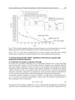
4.3 Plasma-arc cutting
Plasma-arc may be used for either cutting or welding and is the most
widely used thermal process for cutting of aluminium alloys in manual,
mechanised or fully automated modes (Fig. 4.1). In the latter case cuts of
excellent quality can be achieved in material of up to 250mm thickness
at high cutting speeds.
52 The welding of aluminium and its alloys
4.1 Fully programmable CNC plasma-jet cutting system. Courtesy of
Messer Griesheim.
Plasma-arc utilises a specially designed torch in which a tungsten elec-
trode is recessed inside a water-cooled copper annulus, through which is
passed the plasma gas.An arc is struck between the electrode and the work-
piece, transferred arc plasma-arc, or between the electrode and the annulus,
non-transferred arc plasma-arc. Transferred arc plasma-arc is used for
cutting purposes (Fig. 4.2). The plasma gas is heated by the arc to an
extremely high temperature within the annulus and is ionised – it becomes
a plasma. At the same time it expands in volume due to the high tempera-
ture and, being forced through the constriction of the nozzle, reaches very
high velocity. The heat for welding and cutting is therefore provided by
a ‘flame’ or plasma jet of high-velocity gas at temperatures of up to
15000°C, which has the characteristics of being highly concentrated, virtu-
ally insensitive to stand-off distance and extremely stiff. This makes it an
ideal candidate for cutting purposes.
The cut is made by the plasma jet piercing the component to be cut to
form a keyhole, a hole that penetrates completely through the item. This is
filled with the gas and is surrounded by molten metal. The force of the
plasma jet alone may be sufficient to remove this molten metal but with
thicker material a secondary cutting gas may be required to assist in metal
removal. This secondary gas is supplied via a series of holes around the
plasma nozzle designed to blow away the molten metal to give a clean,
Preparation for welding 53
Dross
HF
Electrode
Cooling water
Power
source
Pilot arc
Plasma gas
4.2 Schematic illustrating the principles of plasma-jet cutting.
Courtesy of TWI Ltd.
high-quality and narrow cut. Plasma gases include air, argon, argon–
hydrogen, nitrogen and carbon dioxide. Cutting can be performed manu-
ally or mechanised with higher cutting speeds being achievable with mech-
anised and automated systems.
A plasma cut edge is generally not completely square. The top edge of
the cut may be rounded by some 1 or 2mm, particularly if the cutting energy
is high for the thickness of plate being cut or when high-speed cutting of
thin material is being carried out.The plasma jet also tends to remove more
metal from the upper part of the component than the lower part, resulting
in a cut wider at the top than the bottom with non-parallel sides.This ‘bevel’
angle may be between 3° and 6°. The cut surface may also be rough.The
quality of the cut is affected by gas type, gas flow rate, cutting speed and
operating voltage. High gas flow rates and high voltages will improve
the squareness of the cut and mechanised cutting will give an improved
appearance.
Arc cutting produces a HAZ and may cause melting at the grain bound-
aries. This results in micro-cracking, primarily of the heat-treatable alloys –
the 7000 series being particularly sensitive. As the thickness increases, the
likelihood of such cracking also increases. For this reason it is advisable
to machine back the plasma cut edges by about 3mm, particularly if the
component is to be used in a dynamic loading environment.
The composition of the gas for plasma cutting depends on the required
quality of the cut, the thickness of the metal to be cut and the cost of the
gas. Air is the cheapest option and single gas systems utilising air and a
hafnium electrode have been developed for the cutting of materials up to
approximately 6mm in thickness (Fig. 4.3).
Above this thickness nitrogen, carbon dioxide, argon–hydrogen or
mixtures of these gases may be used. For the thicker materials over, say,
54 The welding of aluminium and its alloys
Cooling
air
Cooling
air
Air Air
4.3 Air plasma cutting. Courtesy of TWI Ltd.