Volume 01 - Properties and Selection Irons, Steels, and High-Performance Alloys Part 6 pot
Bạn đang xem bản rút gọn của tài liệu. Xem và tải ngay bản đầy đủ của tài liệu tại đây (3.35 MB, 160 trang )
Aluminum coatings are applied by hot dip methods at about 675 to 705 °C (1250 to 1300 °F). Aluminum alloy 1100 is
usually used because of its general all-around corrosion resistance. As with any hot dip coating, a metallurgical bond is
formed that consists of an intermetallic alloy layer overlaid with a coating of pure bath material.
Aluminum coatings do not corrode uniformly, as do zinc and cadmium coatings, but rather by pitting. In some cases,
these pits may extend entirely through the coating to the base metal; in others, only through the overlay to the
intermetallic layer. Pits, which may occur in a part soon after exposure, sometimes discolor the coated surface but cause
little damage. The complex aluminum and iron oxide corrosion product seals the pits, and because the corrosion product
is tightly adherent and impervious to attack, corrosion is usually limited. There is little tendency for corrosion to continue
into the ferrous base, and there is none for undercutting and spalling of the coating.
Aluminum coatings will protect steel from scaling at temperatures up to about 540 °C (1000 °F); the aluminum coating
remains substantially the same as when applied, and its life is exceptionally long. Above 650 °C (1200 °F), the aluminum
coating diffuses into the steel to form a highly protective aluminum-iron alloy. This diffusing or alloying is timetemperature dependent; the higher the temperature, the faster the diffusion. However, scaling will not take place until all
the aluminum is used up, which may take a thousand or more hours even at temperatures as high as 760 °C (1400 °F).
The prevention of galling at elevated temperatures is another characteristic of aluminum coatings. Stainless steel fasteners
for use at 650 °C (1200 °F) have been aluminum coated just to prevent galling. Coated nuts can be removed with an
ordinary wrench after many hours at these temperatures, which is impossible with uncoated nuts.
Fastener Performance at Elevated Temperatures
Selection of fastener material is perhaps the single most important consideration in elevated-temperature design. The
basic design objective is to select a bolt material that will give the desired clamping force at all critical points in the joint.
Time- and Temperature-Related Factors. To achieve the basic design objective mentioned above, it is necessary
to balance the three time- and temperature-related factors (modulus, thermal expansion, and relaxation) with a fourth
factor--the amount of initial tightening or clamping force. These three time- and temperature-related factors affect the
elevated-temperature performance of fasteners as follows.
Modulus of Elasticity. As temperature increases, the modulus of elasticity decreases; therefore, less load (or stress) is
needed to impact a given amount of elongation (or strain) to a material than at lower temperatures. This means that a
fastener stretched a certain amount at room temperature to develop preload will exert a lower clamping force at higher
temperature.
Coefficient of Expansion. With most materials, the size of the part increases as the temperature increases. In a joint,
both the structure and the fastener increases in size with an increase in temperature. If the coefficient of expansion of the
fastener exceeds that of the joined material, a predictable amount of clamping force will be lost as temperature increases.
Conversely, if the coefficient of expansion of the joined material is greater, the bolt may be stressed beyond its yield or
even fracture strength, or cyclic thermal stressing may lead to thermal fatigue failure. Thus, matching of materials in joint
design can ensure sufficient clamping force at both room and elevated temperatures without overstressing the fastener.
Relaxation. In a loaded bolt joint at elevated temperature, the bolt material will undergo permanent plastic deformation
(creep) in the direction of the applied stress. This phenomenon, known as relaxation in loaded-joint applications, reduces
the clamping force with time. Relaxation is the most important of the three time- and temperature-related factors and is
discussed in more detail in the article "Elevated-Temperature Properties of Ferritic Steels" in this Volume.
Bolt Steels for Elevated Temperatures. Table 5 lists the recommended steels for bolts to be used at temperatures
between 200 and 370 °C (400 and 700 °F). For higher temperatures up to 480 °C (900 °F), other alloy steels are used. For
example, the medium-alloy chromium-molybdenum-vanadium steel conforming to ASTM A 193, grade B 16, is a
commonly used bolt material in industrial turbine and engine applications to 480 °C (900 °F). An aircraft version of this
steel, AMS 6304, is widely used in fasteners for jet engines. The 5% Cr tool steels, most notably H11, are also used for
fasteners having a tensile strength of 1500 to 1800 MPa (220 to 260 ksi). They retain excellent strength through 480 °C
(900 °F).
For temperatures above 480 °C (900 °F), heat-resistant alloys or superalloys are used for bolt materials. From 480 to 650
°C (900 to 1200 °F), corrosion-resistant alloy A-286 is used. Alloy 718, with a room-temperature tensile strength of 1240
MPa (180 ksi), has some applications in this temperature range. The nickel-base alloys René 41, Waspaloy, and alloy 718
can be used for most applications in the temperature range of 650 to 870 °C (1200 to 1600 °F).
Coatings for Elevated Temperatures. At moderate temperatures, where cadmium and zinc anticorrosion platings
might normally be used, the phenomenon of stress alloying becomes an important consideration. Conventional cadmium
plating, for example, is usable only to 230 °C (450 °F). At somewhat above that temperature, the cadmium is likely to
melt and diffuse into the base material along the grain boundaries, causing cracking by liquid-metal embrittlement, which
can lead to rapid failure. For corrosion protection of high-strength alloy steel fasteners used at temperatures between 230
and 480 °C (450 and 900 °F), special nickel-cadmium coatings such as that described in AMS 2416 are often used. At
extremely high temperatures, coatings must be applied to prevent oxidation of the base material.
Effect of Thread Design on Relaxation. Fastener-manufacturing methods can also influence bolt performance at
elevated temperature. The actual design and shape of the threaded fastener are also important, particularly the root of the
thread. A radiused thread root is a major consideration in room-temperature design, being a requisite for good fatigue
performance. However, at elevated temperature, a generously radiused thread root is also beneficial in relaxation
performance. Starting at an initial preload of 483 MPa (70 ksi), a Waspaloy stud with square thread roots lost a full 50%
of its clamping force after 20 h, with the curve continuing downward, indicating a further loss. A similar stud made with a
large-radiused root lost only 36% of preload after 35 h.
Reference cited in this section
1. T.J. Hughel, "Delayed Fracture of Class 12.8 Bolts in Automotive Rear Suspensions," SAE Technical Paper
Series 820122, Society of Automotive Engineers, 1982
Fastener Tests
The fastener manufacturer must perform periodic tests of the product to ensure that properties are maintained within
specified limits. Guidelines for testing are provided in ASTM F 606 and in SAE J429 (bolts and studs in U.S. inch sizes),
J995 (nuts in U.S. inch sizes), and J1216 (test methods for metric threaded fasteners). When requested in writing by the
purchaser, the manufacturer will furnish a copy of a certified test report.
The most widely accepted method of determining the strength of full-size bolts and studs is a wedge tensile test for
minimum tensile (breaking) strength. Testing of nuts involves a proof stress testing. Proof stress testing of bolts and studs
is also performed before the test for ultimate wedge tensile strength.
The wedge tensile test of bolts accentuates the adverse conditions of bolts assembled under misalignment;
therefore, it is also the most widely used quality control test for ultimate strength and head-to-body integrity and ductility.
The test is performed by placing the wedge under the bolt head and, and by means of suitable fixtures, stressing the bolt
to fracture in a tensile test machine. To meet the requirements of the test, the tensile fracture must occur in the body, or
threaded section, with no fracture at the junction of the body and head. In addition, the breaking strength should meet
specified minimum strength requirements. Details of this test are given in ASTM F 606 and SAE J429.
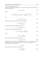
The number of exposed threads between the bolt shank and the beginning of the nut or testing fixture influences the
recorded tensile strength for both coarse-thread and fine-thread bolts. A typical variation of breaking strength with
number of exposed threads is plotted in Fig. 4. The data are for
3
in. diam SAE grade 5 bolts. Because of this variation,
4
the number of exposed threads should be specified for wedge tensile testing of bolts and other threaded fasteners;
generally, six exposed threads are specified.
Fig. 4 Variation of breaking strength with number of exposed threads for
3
in. diam SAE grade 5 bolts.
4
The proof stress of a bolt or stud is a specified stress that the bolt or stud must withstand without detectable
permanent set. For purposes of this test, a bolt or stud is deemed to have incurred no permanent set if the overall length
after application and release of the proof stress is within ±0.013 mm (±0.0005 in.) of its original length. Length
measurements are ordinarily made to the nearest 0.0025 mm (0.0001 in.). Because bolts and studs are manufactured in
specific sizes, the proof stress values are commonly converted to equivalent proof load values, and it is the latter that are
actually used in testing full-size fasteners. To compute proof load, the stressed area must first be determined. Because the
smallest cross-sectional area is in the threads, the stressed area is computed as follows:
0.9743
As (in ²) = 0.7854 D −
N
2
(Eq 1)
where As is the mean equivalent stress area in square inches, D is the nominal diameter in inches, and N is the number of
threads per inch. The equivalent formula for metric threads is:
As(mm2) = 0.7854(D - 0.9382P)2
(Eq 2)
where As is the mean equivalent stress area in millimeters, D is the nominal diameter in millimeters, and P is the thread
pitch in millimeters.
For example,
1
in. diam bolts made to SAE grade 5 requirements have values of mean equivalent stress area for coarse
2
threads (13 threads per inch) and fine threads (20 threads per inch) equal to 0.1419 in.2 and 0.1599 in.2, respectively,
according to Eq 1. These bolts must withstand a proof stress of 585 MPa (85 ksi) without a detectable difference between
the initial length and the length after the proof load has been applied and released. For coarse threads, this requires a proof
load of 53.6 kN (12,060 lb); for fine threads, the proof load is 60.5 kN (13,600 lb).
The proof stress of a nut is determined by assembling it on a hardened and threaded mandrel or on a test bolt
conforming to the particular specification. The specified proof load for the nut is determined by converting the specified
proof stress, using the mean equivalent stress area calculated for the mandrel or test bolt. This proof load is applied
axially to the nut by a hardened plate, as shown in Fig. 5. The thickness of the plate is at least equal to the diameter of the
mandrel or test bolt. The diameter of the hole in the plate is a specified small amount greater than that of the mandrel or
test bolt diameter. To demonstrate acceptable proof stress, the nut must resist the specified proof load without failure by
stripping or rupture, and it must be removable from the mandrel or test bolt by hand after initial loosening.
Fig. 5 Test setup for the proof testing of nuts
Details relating to the prescribed proof stress tests and other requirements for threaded steel fasteners of various sizes in
both coarse and fine threads are available in SAE J429 and J995 for fasteners made to SAE strength grades or ISO 898 for
fasteners made to ISO property classes. Additional information is also available in ASTM F 606.
Mechanical Properties
The major mechanical properties of fasteners include:
•
•
•
•
Tensile (breaking) strength with a static load
Hardness
Fatigue strength with a dynamic loading
Resistance to stress-corrosion cracking or other forms of environmentally induced cracking, such as
hydrogen embrittlement and liquid-metal embrittlement
The following sections briefly review these mechanical properties of threaded steel fasteners.
Strengths With Static Loads. Table 2 and 3 list the specified mechanical properties of the commonly used SAE
strength grades and ISO property classes of steel bolts, studs, and nuts. As previously noted, the grades or classes of these
specifications are based on tensile strength for bolts and stubs or proof stress for nuts.
Grade 1038 steel is one of the most widely used steels for threaded fasteners. Typical distributions of tensile properties
for bolts and cap screws made from 1038 steel, as evaluated by the wedge tensile test, are shown in Fig. 6. These data
were obtained from one plant and represent tests from random lots of SAE grade 5 fasteners. The three histograms in Fig.
6 show three distributions typical of grade 5 fasteners. No significance should be attached to the apparent difference
between average values, especially for the two hex-head bolts of different lengths. Specifications require only that bolt
strength exceed a specified minimum value, not that bolts of different sizes have statistically equivalent average strengths.
Fig. 6 Typical strength distributions for 10° wedge tests of 1038 steel cap screws and bolts
Hardness Versus Tensile Strength. To ensure freedom from the effects of decarburization and nonrepresentative
cooling rates during the quench, there is really only one preferred location for checking hardness. This location is the midradius of a transverse section taken one diameter from the threaded end of the bolt (Fig. 7). If the hardness tests are not
taken at this location, then greater scatter will occur in the relation between hardness and tensile strength. For example,
hardness tests taken at the bolt head will probably result in more scatter because the greater thermal mass of the bolt head
products differences in quench efficiency and may result in incomplete hardening.
Fig. 7 Relation of hardness and tensile strength for SAE grade 5 bolts made of 1038 steel
The bolt shown in Fig. 7 was made from one heat of 1038 steel of the following composition: 0.38% C, 0.74% Mn,
0.08% Si 0.025% P, 0.040% S, 0.08% Cr, 0.07% Ni, and 0.12% Cu. The bolt was quenched in water from 845 °C (1550
°F) and tempered at different temperatures in the range 365 to 600 °C (690 to 1110 °F) to produce a range of hardness of
20 to 40 HRC.
Figure 8 shows the results of a cooperative study in which eight laboratories tested a large number of bolts made from a
single heat of 1038 steel. There were eight different lots of bolts, each heat treated to a different hardness level. Each of
the eight laboratories tested bolts from all eight lots. Hardness readings were taken on a transverse section through the
threaded portion of the bolt at the mid-radius of the bolt. The tranverse section was located one diameter from the
threaded end of the bolt.
Fig. 8 Hardness distribution for eight lots of 1038 steel bolts. Bolts, 13 mm (
1
in.) in diameter, were all made
2
from one heat of steel. The bolts were heat treated in one plant to eight different levels of nominal hardness.
Tests were made in the originating plant and in seven other laboratories.
Fatigue Failures. Fatigue is one of the most common failure mechanisms of threaded fasteners, particularly if
insufficient tightening of the fasteners results in flexing. To eliminate this cause of fatigue fracture at room temperature;
the designer should specify as high an initial preload as practical. Higher clamping forces make more rigid joints and
therefore reduce the rate of fatigue crack propagation from flexing. The optimum fastener-torque values for applying
specific loads to the joint have been determined for many high-strength fasteners. However, these values should be used
with caution, because the tension produced by a selected torque value depends directly on the friction between the
contacting threads. The use of an effective lubricant on the threads may result in overloading of the fastener, while the use
of a less effective lubricant may result in a loose joint. With proper selection of materials, proper design of bolt-and-nut
bearing surfaces, and the use of locking devices, the assumption is that the initial clamping force will be sustained during
the life of the fastened joint. This assumption cannot be made in elevated-temperature design. At elevated temperature,
the induced bolt load will decrease with time as a result of creep.
Fatigue Strength. The factors affecting the fatigue strength of threaded fasteners include surface condition, mean
stress, stress range, and the grain pattern at the head-to-shank fillet. If bolts made of two different steels have equivalent
hardnesses throughout identical sections, their fatigue strengths will be similar (Fig. 9) as long as other factors such as
mean stress, stress range, and surface condition are the same. If the results of fatigue tests on standard test specimens were
interpreted literally, high-carbon steels would be selected for bolts. Actually, steels of high carbon content (>0.55% C) are
unsuitable because they are notch sensitive.
Fig. 9 Fatigue data for 1040 and 4037 steel bolts. The bolts (
3
by 2 in., 16 threads to the inch) had a
8
hardness of 35 HRC. Tensile properties of the 1040 steel at three-thread exposure were yield strength, 1060
MPa (154 ksi); tensile strength (axial), 1200 MPa (175 ksi); tensile strength (wedge), 1190 MPa (173 ksi). For
the 4037 steel: yield strength, 1110 MPa (161 ksi); tensile strength (axial), 1250 MPa (182 ksi); tensile
strength (wedge), 1250 MPa (182 ksi)
The principal design feature of a bolt is the threaded section, which establishes a notch pattern inherent in the part because
of its design. The form of the threads, plus any mechanical or metallurgical condition that also creates a surface notch, is
much more important than steel composition in determining the fatigue strength of a particular lot of bolts. Some of these
factors are discussed below.
Causes and Prevention of Fatigue Crack Initiation. The origin of a fatigue crack is usually at some point of
stress concentration, such as an abrupt change of section, a deep scratch, a notch, a nick, a fold, a large inclusion, or a
marked change in grain size. Fatigue failures in bolts often occur in the threaded section immediately adjacent to the edge
of the nut (or mating part) on the washer side, at or near the first thread inside the nut (or mating part). This area of stress
concentration occurs because the bolt elongates as the nut is tightened, thus producing increased loads on the threads
nearest the bearing face of the nut, which add to normal service stresses. This condition is alleviated to some extent by
using nuts of a softer material that will yield and distribute the load more uniformly over the engaged threads. Significant
additional improvement in fatigue life is also obtained by rolling (cold working) the threads rather than cutting them and
also by rolling threads after heat treatment rather than before.
Other locations of possible fatigue failure of a bolt under tensile loading are the thread runout and the head-to-shank fillet.
Like the section of the bolt thread described in the previous paragraph, these two locations are also areas of stress
concentration. Any measures that decrease stress concentration can lead to improved fatigue life. Typical examples of
such measures are the use of UNJ increased root radius threads (see MIL-S-8879A) and the use of internal thread designs
that distribute the load uniformly over a large number of bolt threads. Shape and size of the head-to-shank fillet are
important, as is a generous radius from the thread runout to the shank. In general, the radius of this fillet should be as
large as possible while at the same time permitting adequate head-bearing area. This requires a design trade-off between
the head-to-shank radius and the head-bearing area to achieve optimum results. Cold working of the head fillet is another
common method of preventing fatigue failure because it induces a residual compressive stress and increases the material
strength.
Several other factors are also important in avoiding fatigue fracture at the head-to-shank fillet. The heads of most
fasteners are formed by hot or cold forging, depending on the type of material and size of the bolt. In addition to being a
relatively low-cost manufacturing method, forging provides smooth, unbroken grain flow lines through the head-to-shank
fillet, which closely follows the external contour of the bolt (Fig. 10) and therefore minimizes stress raisers, which
promote fatigue cracking. In the hot forging of fastener heads, temperatures must be carefully controlled to avoid
overheating, which may cause grain growth. Several failures of 25 mm (1 in.) diam type H-11 airplane-wing bolts
quenched and tempered to a tensile strength of 1800 to 1930 MPa (260 to 280 ksi) have been attributed to stress
concentration that resulted from a large grain size in the shank. Other failures in these 25 mm (1 in.) diam bolts, as well as
in other similarly quenched and tempered steel bolts, were the result of cracks in untempered martensite that formed as a
result of overheating during finish grinding.
Fig. 10 Uniform, unbroken grain flow around the contours of the forged head of a threaded fastener. The
uniform, unbroken grain flow minimizes stress raisers and unfavorable shear planes and therefore improves
fatigue strength.
Influence of the Thread-Forming Method on Bolt Fatigue Strength. The method of forming the thread is an
important factor influencing the fatigue strength of bolts. Specifically, there is a marked improvement when threads are
rolled rather than either cut or ground, particularly when the threads are rolled after the bolt has been heat treated (Fig.
11).
Fig. 11 Fatigue limits for roll-threaded steel bolts. (a) Four different lots of bolts that were roll threaded, then
heat treated to average hardness of 22.7, 26.6, 27.6, and 32.6 HRC. (b) Five different lots that were heat
treated to average hardnesses of 23.3, 27.4, 29.6, 31.7, and 33.0 HRC, then roll threaded. Bolts having higher
hardnesses in each category had higher fatigue strengths.
Other factors being equal, a bolt with threads properly rolled after heat treatment--that is, free from mechanical
imperfections--has a higher fatigue limit than one with cut threads. This is true for any strength category. The cold work
of rolling increases the strength at the weakest section (the thread root) and imparts residual compressive stresses, similar
to those imparted by shot peening. The larger and smoother root radius of the rolled thread also contributes to its
superiority. Because of the fatigue life concern, all bolts and screws greater than grade 1 and less than 19 mm (
3
in.) in
4
diameter and 150 mm (6 in.) in length are to be roll threaded. Studs and larger bolts and screws may have the threads
rolled, cut or ground.
Effect of Surface Treatment on Fatigue. Light cases, such as from carburizing or carbonitriding, are rarely
recommended and should not be used for critical externally threaded fasteners, such as bolts, studs, or U-bolts. The cases
are quite brittle and crack when the fasteners are tightened or bent in assembly or service. These cracks may then lead to
fatigue cracking and possible fracture.
Chromium and nickel platings decrease the fatigue strength of threaded sections and should not be used except in a few
applications, such as automobile bumper studs or similar fasteners that operate under conditions of low stress and require
platings for appearance. Cadmium and zinc platings slightly reduce fatigue strength. Electroplated parts for high-strength
applications should be treated after plating to eliminate or minimize hydrogen embrittlement (which is a strong
contributor to fatigue cracking).
Installation. As noted at the beginning of this section on fatigue failures, bolt loading is a major factor in the fatigue
failure of threaded fasteners. When placed into service, bolts are most likely to fail by fatigue if the assemblies involve
soft gaskets or flanges, or if the bolts are not properly aligned and tightened. Fatigue resistance is also related to clamping
force. In many assemblies, a certain minimum clamping force is required to ensure both proper alignment of the bolt in
relation to other components of the assembly and proper preload on the bolt. The former ensures that the bolt will not be
subjected to undue eccentric loading, and the latter that the correct mean stress is established for the application. In some
cases, clamping stresses that exceed the yield strength may be desirable; experiments have shown that bolts clamped
beyond the yield point have better fatigue resistance than bolts clamped below the yield point.
Decreasing the bolt stiffness can also reduce cyclic stresses. Methods commonly used are reduction of the cross-sectional
area of the shank to form a waisted shank and rolling the threads further up the exposed shank to increase the "spring"
length.
Stress-corrosion cracking (SCC) is an intergranular fracture mechanism that sometimes occurs in highly stressed
fasteners after a period of time, and it is caused by a corrosive environment in conjunction with a sustained tensile stress
above a threshold value. An adverse grain orientation increases the susceptibility of some materials to stress corrosion.
Consequently, SCC can be prevented by excluding the corrodent, by keeping the static tensile stress of the fastener below
the critical level for the material and grain orientation involved, or by changing to a less susceptible material or material
condition. Because tensile loads (even residual tensile loads) are required to produce SCC, compressive residual stresses
may prevent SCC.
As with the environmentally induced cracking from hydrogen embrittlement and liquid-metal embrittlement (see the
article "Embrittlement of Steels" in this Volume), the understanding of SCC is largely phenomenological, without any
satisfactory mechanistic model for predicting SCC or the other forms of environmentally induced cracking. This lack of
mechanistic predictability of SCC is particularly unfortunate because measurable corrosion usually does not occur before
or during crack initiation or propagation. Even when corrosion does occur, it is highly localized (that is, pitting, crevice
attack) and may be difficult to detect. Moreover, SCC is a complex synergistic phenomenon resulting from the combined
simultaneous interaction of mechanical and chemical conditions. Pre-corrosion followed by loading in an inert
environment will not result in any observable crack propagation, while simultaneous environmental exposure and
application of stress will cause time-dependent subcritical crack propagation.
The susceptibility of a metal to SCC depends on the alloy and the corrodent. The National Association of Corrosion
Engineers, the Materials Technology Institute of the Chemical Process Industries, and others have published tables of
corrodents known to cause SCC of various metal alloy systems (Ref 2, 3, 4). This literature should be used only as a guide
for screening candidate materials for further in-depth investigation, testing, and evaluation. In general, plain carbon steels
are susceptible to SCC by several corrodents of economic importance, including aqueous solutions of amines, carbonates,
acidified cyanides, hydroxides, nitrates, and anhydrous ammonia. Carbon steels, low-alloy steels, and H-11 tool steels
with ultimate tensile strengths above 1380 MPa (200 ksi) are susceptible to SCC in a seacoast environment. Of the
various bolt steels, bolts made from ISO class 12.8 have experienced failures for SCC in automotive applications (Ref 1).
Stainless steels are also susceptible to SCC in some environments.
Even though the micromechanistic causes of SCC are not entirely understood, some investigators consider SCC to be
related to hydrogen damage and not strictly an active-path corrosion phenomenon. Although hydrogen can be a factor in
the SCC of certain alloys (see Example 1), sufficient data are not available to generalize this concept. For example, SCC
can be assisted by such factors as nuclear irradiation. More information on SCC is available in Corrosion, Volume 13 of
ASM Handbook.
Example 1: Hydrogen-Assisted SCC Failure of Four AISI 4137 Steel Bolts.
Figure 12 shows an example of hydrogen-assisted SCC failure of four AISI 4137 steel bolts having a hardness of 42
HRC. Although the normal service temperature (400 °C, or 750 °F) was too high for hydrogen embrittlement, the bolts
were also subjected to extended shutdown periods at ambient temperatures. The corrosive environment contained trace
hydrogen chloride and acetic acid vapors as well as calcium chloride if leaks occurred. The exact service life was
unknown. The bolt surfaces showed extensive corrosion deposits. Cracks had initiated at both the thread roots and the
fillet under the bolt head. Figure 12(b) shows a longitudinal section through the failed end of one bolt. Multiple, branched
cracking was present, typical of hydrogen-assisted SCC in hardened steels. Chlorides were detected within the cracks and
on the fracture surface. The failed bolts were replaced with 17-4 PH stainless steel bolts (Condition H 1150M) having a
hardness of 22 HRC (Ref 5).
Fig. 12 4137 steel bolts (hardness: 42 HRC) that failed by hydrogen-assisted SCC caused by acidic chlorides
from a leaking polymer solution. (a) Overall view of failed bolts. (b) Longitudinal section through one of the
failed bolts in (a) showing multiple, branched hydrogen-assisted stress-corrosion cracks initiating from the
thread roots. Source: Ref 5
References cited in this section
1. T.J. Hughel, "Delayed Fracture of Class 12.8 Bolts in Automotive Rear Suspensions," SAE Technical Paper
Series 820122, Society of Automotive Engineers, 1982
2. Corrosion Data Survey--Metals Section , 5th ed., National Association of Corrosion Engineers, 1974, p. 268269
3. D.R. McIntyre and C.P. Dillon, Guidelines for Preventing Stress Corrosion Cracking in the Chemical
Process Industries , Publication 15, Materials Technology Institute of the Chemical Process Industries, 1985,
p 8-14
4. The Role of Stainless Steels in Petroleum Refining, American Iron and Steel Institute, 1977, p 41
5. D. Warren, Hydrogen Effects on Steel, in Process Industries Corrosion, National Association of Corrosion
Engineers, 1986, p 31-43
Fabrication
Most bolts are made by cold heading. Other cold-forming methods, including cold extrusion, are used in the manufacture
of threaded fasteners. Current technology is such that not only low-carbon steels but also medium-carbon and even lowalloy steels can be successfully impact extruded.
Parts having heads that are large in relation to the shank diameter can be hot headed or produced cold on a two-die, threeblow machine. Hot heading is also more practical for bolts with diameters larger than about 32 mm (1
1
in.) because of
4
equipment limitations and increased probability of tool failures with cold heading.
Platings and Coatings. Mots carbon steel fasteners are plated or coated. Common coatings are zinc, cadmium, and
phosphate and oil. Other supplementary finishes are gaining popularity, especially in critical applications. The principal
reason for fastener plating or coating is corrosion resistance (see the section "Corrosion Protection" in this article),
although the appearance and the installation torque-tension relationship are also improved.
Plating is the deposition of metal onto the surface of the base metal. For commercial applications, plating is achieved by
electroplating, hot dipping, or mechanical application. In general, the addition of plating increases the dimensions of the
fastener by two times the plating thickness and by almost four times the plating thickness in the thread dimensions. The
thread assembly may be affected by the increase in fastener size due to plating.
High-strength fasteners, usually with higher carbon content, are susceptible to hydrogen embrittlement when being acid
cleaned, electrocleaned, or electroplated. Hydrogen penetration into a fastener can be minimized by baking at about 190
to 200 °C (375 to 400 °F) for 3 to 24 h. For applications in which hydrogen embrittlement is a concern or for a critical
application of high-strength fasteners, the mechanical application of plating should be considered.
Clamping Forces
To operate effectively and economically, threaded fasteners should be designed to be torqued near the proof stress, as
dictated by the cross-sectional area of the load-carrying parts of the fastener and the desired clamping force. The actual
clamping force attained in any assembly will be influenced by such factors as:
•
•
•
Roughness of the mating surfaces
Coatings, contaminants, or lubricants on the mating surfaces
Platings or lubricants on the threads
Typically, torque values are established to result in a clamping force equal to about 75% of the proof load. For some
applications, bolts are torqued beyond their proof stress with no detrimental results, provided they are permanent fasteners
holding static loads.
Because it is difficult to measure bolt tension (clamping force) in production installations, torque values are used in most
applications. Some critical joints in assembly-line processes are using torque-angle or torque-to-yield methods of
tightening. In the torque-angle method, the bolt is torqued to a low seating torque level to mate all surfaces, then rotated a
specific angle. The angle rotation has a linear relationship with extension because of the constant pitch and therefore with
clamp load. In the torque-to-yield method, torque and angular rotation are monitored during, installation by a
microprocessor and bolt rotation continues until the relationship between the two is not linear. This point is defined as the
yield point in torque tension.
The clamping forces generated at given torques are very dependent on the coefficient of friction at the threads and at the
bearing face; therefore, they are highly dependent on fastener coatings. Common fastener coatings are zinc, cadmium, and
phosphate and oil.
The maximum clamping force that can be effectively employed in any bolt is often limited by the compressive strength of
the materials being bolted. If this value is exceeded, the bolt head or nut will be pulled into the parts being bolted, with a
subsequent reduction in clamping force. The assembly then becomes loose, and the bolt is susceptible to fatigue failure. If
high-tensile bolts are necessary to join low compressive strength materials, hardened washers should be used under the
head of the bolt and under the nut to distribute bearing pressure more evenly and to avoid the condition described above.
The value of high clamping forces, apart from lessening the possibility of the nut loosening, is that the working stresses
(against solid abutments) are always less than the clamping forces induces in a properly selected bolt. This ensures against
cyclic stress and possible fatigue failure.
References
1. T.J. Hughel, "Delayed Fracture of Class 12.8 Bolts in Automotive Rear Suspensions," SAE Technical Paper
Series 820122, Society of Automotive Engineers, 1982
2. Corrosion Data Survey--Metals Section , 5th ed., National Association of Corrosion Engineers, 1974, p. 268269
3. D.R. McIntyre and C.P. Dillon, Guidelines for Preventing Stress Corrosion Cracking in the Chemical
Process Industries , Publication 15, Materials Technology Institute of the Chemical Process Industries, 1985,
p 8-14
4. The Role of Stainless Steels in Petroleum Refining, American Iron and Steel Institute, 1977, p 41
5. D. Warren, Hydrogen Effects on Steel, in Process Industries Corrosion, National Association of Corrosion
Engineers, 1986, p 31-43
Steel Springs
Revised by Loren Godfrey, Associated Spring/Barnes Group, Inc.
Introduction
STEEL SPRINGS are made in many types, shapes, and sizes, ranging from delicate hairsprings for instrument meters to
massive buffer springs for railroad equipment. The major portion of this article discusses those relatively small steel
springs that are cold wound from wire. Relatively large, hot-wound springs are quite different from cold-wound springs
and are treated in a separate section. Flat and leaf springs are also treated separately to the extent that they differ from
wire springs in material and fabrication.
Wire springs are of four types: compression springs (including die springs), extension springs, torsion springs, and wire
forms. Compression springs are open wound with varying space between the coils and are provided with plain, plain and
ground, squared, or squared and ground ends. The spring can be cylindrical, conical, barrel, or hour glass shaped.
Extension springs are normally close wound, usually with specified initial tension, and, because they are used to resist
pulling forces, are provided with hook or loop ends to fit the specific application. Ends may be integral parts of the spring
or specially inserted forms. Torsion springs are usually designed to work over an arbor and to resist a force that causes the
spring to wind. Wire forms are made in a wide variety of shapes and sizes.
Flat springs are usually made by stamping and forming of strip material into shapes such as spring washers. However,
there are other types, including motor springs (clock type), constant-force springs, and volute springs, that are wound
from strip or flat wire.
Chemical composition, mechanical properties, surface quality, availability, and cost are the principal factors to be
considered in selecting steel for springs. Both carbon and alloy steels are used extensively.
Steels for cold-wound springs differ from other constructional steels in four ways.
•
•
•
•
They are cold worked more extensively
They are higher in carbon content
They can be furnished in the pretempered condition
They have higher surface quality
The first three items increase the strength of the steel, and the last improves fatigue properties. For flat, cold-formed
springs made from steel strip or flat wire, narrower ranges of carbon and manganese are specified than for cold-wound
springs made from round or square wire.
Where special properties are required, spring wire or strip made of stainless steel, a heat-resistant alloy, or a nonferrous
alloy can be substituted for the carbon or alloy steel, provided that the design of the spring is changed to compensate for
the differences in properties between the materials (see the section "Design" in this article).
Table 1 lists grade, specification, chemical composition, properties, method of manufacture, and chief applications of the
materials commonly used for cold-formed springs. Hot-formed carbon and alloy steel springs are discussed in this article.
Table 1 Common wire and strip materials used for cold-formed springs
Material
type
Grade and
specification
Nominal
composition, %
Tensile properties
Torsion properties
Minimum
tensile
strength(a),
MPa (ksi)
Modulus
of
elasticity
(E),
GPa (psi
× 106)
Design
stress,
% of
minimum
tensile
strength(b)
Hardness,
HRC(c)
Max
allowable
temperature,
°C ( °F)
Method of manufacture, chief
applications, special properties
Modulus
of
rigidity
(G),
GPa (psi
× 106)
Cold drawn wire
High-carbon
steel
Music wire, ASTM
A 228
C 0.70-1.00, Mn
0.20-0.60
1590-2750
(230-399)
210 (30)
45
80 (11.5)
41-60
120 (250)
Drawn to high and uniform tensile
strength; for high-quality springs
and wire forms
Hard drawn, ASTM
A 227
C 0.45-0.85, Mn
0.30-1.30
Class I
1010-1950
(147-283)
Class II
1180-2230
(171-324)
210 (30)
40
80 (11.5)
31-52
120 (250)
For average-stress applications;
lower-cost springs and wire forms
High-tensile hard
drawn, ASTM A 679
C 0.65-1.00, Mn
0.20-1.30
1640-2410
(238-350)
210 (30)
45
80 (11.5)
41-60
120 (250)
For higher-quality springs and wire
forms
Oil tempered, ASTM
A 229
C 0.55-0.85, Mn
0.30-1.20
Class I
1140-2020
(165-294)
Class II
1320-2330
(191-324)
210 (30)
45
80 (11.5)
42-55
120 (250)
Heat treated before fabrication; for
general-purpose springs
Carbon VSQ(d),
ASTM A 230
C 0.60-0.75, Mn
0.60-0.90
1480-1650
(215-240)
210 (30)
45
80 (11.5)
45-49
120 (250)
Heat treated before fabrication;
good surface condition and uniform
tensile strength
Alloy steel
1310-2070
(190-300)
210 (30)
45
80 (11.5)
41-55
220 (425)
Heat treated before fabrication; for
shock loads and moderately
elevated temperature; ASTM A 232
for valve springs
C 0.60-0.75, Cr
0.35-0.60, V 0.100.25
1410-2000
(205-290)
...
...
...
...
...
Heat treated before fabrication; for
valve springs and moderately
elevated temperatures
Chromium silicon,
ASTM A 877(d), A
401
C 0.51-0.59, Cr
0.60-0.80, Si 1.201.60
1620-2070
(235-300)
210 (30)
45
80 (11.5)
48-55
245 (475)
Heat treated before fabrication; for
shock loads and moderately
elevated temperature; ASTM A 877
for valve springs
Type 302(18-8),
ASTM A 313
Cr 17-19, Ni 8-10
860-2240
(125-325)
190 (28)
30-40
69 (10.0)
35-45
290 (550)
General-purpose corrosion and
heat resistance; magnetic in spring
temper
Type 316, ASTM A
313
Cr 16-18, Ni 1014, Mo 2-3
760-1690
(110-245)
190 (28)
40
69 (10.0)
35-45
290 (550)
Good heat resistance; greater
corrosion resistance than 302;
magnetic in spring temper
Type 631 (17-7 PH),
ASTM A 313
Nonferrous
alloys
C 0.48-0.53, Cr
0.80-1.10, V 0.15
min
Modified chromium
vanadium VSQ(d),
ASTM A 878
Stainless steel
Chromium
vanadium, ASTM A
231, A 232(d)
Cr 16-18, Ni 6.507.75, Al 0.75-1.50
Condition
CH-900
1620-2310
(235-335)
200 (29.5)
45
76 (11.0)
38-57
340 (650)
Precipitation hardened after
fabrication; high strength and
general-purpose corrosion
resistance; magnetic in spring
temper
Copper alloy 510
(phosphor bronze A),
ASTM B 159
Cu 94-96, Sn 4.25.8
720-1000
(105-145)
100 (15)
40
43 (6.25)
98-104(e)
90 (200)
Good corrosion resistance and
electrical conductivity
Copper alloy 170
(beryllium copper)
ASTM B 197
Cu 98, Be 1.8-2.0
1030-1590
(150-230)
130 (18.5)
45
50 (7.0)
35-42
200 (400)
Can be mill hardened before
fabrication; good corrosion
resistance and electrical
conductivity; high mechanical
properties
Monel 400, AMS
7233
1000-1240
(145-180)
180 (26)
40
65 (9.5)
23-32
230 (450)
Good corrosion resistance at
moderately elevated temperature
Monel K-500, QQN-286(f)
Ni 65, Cu 29.5, Al
2.8
110-1380
(160-200)
180 (26)
40
65 (9.5)
23-35
290 (550)
Excellent corrosion resistance at
moderately elevated temperature
A-286 alloy
Fe 53, Ni 26, Cr
15
1100-1380
(160-200)
200 (29)
35
72 (10.4)
35-42
510 (950)
Precipitation hardened after
fabrication; good corrosion
resistance at elevated temperature
Inconel 600, QQ-W390(f)
Ni 76, Cr 15.8, Fe
7.2
1170-1590
(170-230)
215 (31)
40
76 (11.0)
35-45
370 (700)
Good corrosion resistance at
elevated temperature
Inconel 718
Ni 52.5, Cr 18.6,
Fe 18.5
1450-1720
(210-250)
200 (29)
40
77 (11.2)
45-50
590 (1100)
Precipitation hardened after
fabrication; good corrosion
resistance at elevated temperature
Inconel X-750,
;AMS 5698, 5699
Hightemperature
alloys
Ni 66, Cu 31.5
Ni 73, Cr 15, Fe
6.75
No. 1 temper
1070 (155)
Spring
temper
1310-1590
(190-230
215 (31)
40
83 (12.0)
No. 1 34-39
Spring
42-48
400-600
(750-1100)
Precipitation hardened after
fabrication; good corrosion
resistance at elevated temperature
Medium carbon
(1050), ASTM A
682
C 0.47-0.55, Mn
0.60-0.90
Tempered
1100-1930
(160-280)
210 (30)
...
...
Annealed 85
max(e),
tempered 38-50
120 (250)
General-purpose applications
"Regular" carbon
(1074), ASTM A
682
C 0.69-0.80, Mn
0.50-0.80
Tempered
1100-2210
(160-320)
210 (30)
...
...
Annealed 85
max(e),
tempered 38-50
120 (250)
Most popular material for flat
springs
High carbon (1095),
C 0.90-1.04, Mn
Tempered
1240-2340
210 (30)
...
...
Annealed 88
max(e),
120 (250)
High-stress flat springs
Cold-rolled strip
Carbon steel
ASTM A 682
C 0.48-0.53, Cr
0.80-0.10, V 0.15
min
1380-1720
(200-250)
210 (30)
...
...
42-48
220 (425)
Heat treated after fabrication; for
shock loads and moderately
elevated temperature
C 0.51-0.59, Cr
0.60-0.80, Si 1.201.60
1720-2240
(250-325)
210 (30)
...
...
47-51
245 (475)
Heat treated after fabrication; for
shock loads and moderately
elevated temperature
Type 301
Cr 16-18, Ni 6-8
1655-2650
(240-270)
190 (28)
...
...
48-52
150 (300)
Rolled to high yield strength;
magnetic in spring temper
Cr 17-19, Ni 8-10
1280-1590
(185-230)
190 (28)
...
...
42-48
290 (550)
General-purpose corrosion and
heat resistance; magnetic in spring
temper
Type 316
Cr 16-18, Ni 1014, Mo 2-3
1170-1590
(170-230)
190 (28)
...
...
38-48
290 (550)
Good heat resistance; greater
corrosion resistance than 302;
magnetic in spring temper
Type 631 (17-7 PH),
ASTM A 693
Nonferrous
alloys
Chromium
vanadium, AMS
6455
Type 302 (18-8)
Stainless steel
(180-340)
Chromium silicon,
AISI 9254
Alloy steel
0.30-0.50
tempered 40-52
Cr 16-18, Ni 6.507.75, Al 0.75-1.50
Condition
CH-900
1655 (240)
200 (29)
...
...
46 min
340 (650)
Precipitation hardened after
fabrication; high strength and
general-purpose corrosion
resistance; magnetic in spring
temper
Copper alloy 510
(phosphor bronze A),
ASTM B103
Cu 94-96, Sn 4.25.8
650-750 (95110)
100 (15)
...
...
94-98(e)
90 (200)
Good corrosion resistance and
electrical conductivity
Copper alloy 170
(beryllium copper),
ASTM B 194
Cu 98, Be 1.6-1.8
1240-1380
(180-200)
130 (18.5)
...
...
39 min
200 (400)
Can be mill hardened before
fabrication; good corrosion
resistance and electrical
conductivity; high mechanical
properties
Monel 400, AMS
4544
690-970
(100-140)
180 (26)
...
...
98 min(e)
230 (450)
Good corrosion resistance at
moderately elevated temperature
Monel K-500 QQ-N286(f)
Ni 65, Cu 29.5, Al
2.8
1170-1380
(170-200)
180 (26)
...
...
34 min
290 (550)
Excellent corrosion resistance at
moderately elevated temperature
A-286 alloy, AMS
5525
Fe 53, Ni 26, Cr
15
1100-1380
(160-200)
200 (29)
...
...
30-40
510 (950)
Precipitation hardened after
fabrication; good corrosion
resistance at elevated temperature
Inconel 600, ASTM
B 168, AMS 5540
Ni 76, Cr 15.8, Fe
7.2
1000-1170
(145-170)
215 (31)
...
...
30 min
370 (700)
Good corrosion resistance at
elevated temperature
Inconel 718, AMS
5596, AMS 5597
Ni 52.5, Cr 18.6,
Fe 18.5
1240-1410
(180-204)
200 (29)
...
...
36
590 (1100)
Precipitation hardened after
fabrication; good corrosion
resistance at elevated temperature
Inconel X-750,
AMS 5542
Hightemperature
alloys
Ni 66, Cu 31.5
Ni 73, Cr 15, Fe
6.75
1030 (150)
215 (31)
...
...
30 min
400-590
(750-1100)
Precipitation hardened after
fabrication; good corrosion
resistance at elevated temperature
Source: Ref 1
(a) Minimum tensile strength varies within the given range according to wire diameter (see the applicable specification). Maximum tensile strength is generally about 200 MPa (30 ksi) above the minimum
tensile strength.
(b) For helical compression or extension springs; design stress of torsion and flat springs taken as 75% of minimum tensile strength.
(c) Correlation between hardness and tensile properties of wire is approximate only and should not be used for acceptance or rejection.
(d) Valve-spring quality.
(e) HRB values.
(f) Federal specification.
Reference
1. Handbook of Spring Design, Spring Manufacturers Institute, 1988
Mechanical Properties
Steels of the same chemical composition may perform differently because of different mechanical and metallurgical
characteristics. These properties are developed by the steel producer through cold work and heat treatment or by the
spring manufacturer through heat treatment. Selection of round wire for cold-wound springs is based on minimum tensile
strength for each wire size and grade (Fig. 1) and on minimum reduction in area (40% for all sizes).
Fig. 1 Minimum tensile strength of steel spring wire. VSQ, valve-spring quality
Rockwell hardness and tensile strength for any grade of spring steel strip depend on thickness. The same properties in
different thicknesses can be obtained by specifying different carbon contents. The relationship between thickness of
spring steel strip containing 0.50 to 0.95% C and Rockwell hardness is shown in Fig. 2. The optimum hardness of a spring
steel increases gradually with decreasing thickness.
Fig. 2 Effect of strip thickness on the optimum hardness of spring steel strip for high-stress use. Hardness on
HRC scale may be lowered 3 to 4 points for greater toughness. Instability of ductility is sometimes encountered
above 57 HRC.
The hardness scale that can be used for thin metal depends on the hardness and the thickness of the metal (see Table 3 in
the article "Rockwell Hardness Testing" in Mechanical Testing, Volume 8 of ASM Handbook, formerly 9th Edition
Metals Handbook). For testing spring steel strip, which has a minimum hardness of 38 HRC, the Rockwell C scale is used
for metal thicker than 0.89 mm (0.035 in.). For thickness ranges of 0.89 to 0.64 mm (0.035 to 0.025 in.), 0.64 to 0.5 mm
(0.025 to 0.020 in.), and 0.5 to 0.33 mm (0.020 to 0.013 in.), the Rockwell 45N, 30N, and 15N scales are preferred. For
thickness less than 0.33 mm (0.013 in.), the Vickers (diamond pyramid) scale is recommended. As the strip hardness
increases, the thickness that can be safely tested decreases. It has been found that the readings obtained with the Vickers
indentor are less subject to variation in industrial circumstances than those obtained with the Knoop indentor. The 500 g
load Vickers test is used for spring steel strip in thicknesses as low as 0.08 mm (0.003 in.).
If readings are made using the proper hardness scale for a given thickness and hardness, they can be converted to HRC
values using charts like those in the appendix to the article "Miscellaneous Hardness Tests" in Mechanical Testing,
Volume 8 of ASM Handbook, formerly 9th Edition Metals Handbook. Similar charts appear in ASTM A 370 and in the
cold-rolled flat wire section of the Steel Products Manual of the American Iron and Steel Institute (AISI). Chart No. 60
published by Wilson Instrument Division, American Chain & Cable Company, Inc., can also be used for this conversion.
For specific steel springs, hardness can be held to within 4 points on the Rockwell C scale.
Note that in Table 1 and in the section "Design" in this article, design-stress values are given as percentages of minimum
tensile strength. These values apply to springs that are coiled or formed and then stress relieved, which are used in
applications involving relatively few load cycles. If each spring is coiled or formed so as to allow for some set, and then
deflected beyond the design requirements, higher design stresses can be used. This is discussed in the section "Residual
Stresses" in this article.
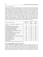
As a further aid in selecting steels for springs, Table 2 lists the suitable choices for cold-wound helical springs in various
combinations combinations of size, stress, and service. Each recommendation is the most economical steel that will
perform satisfactorily under the designated conditions and that is commercially available in the specific size.
Table 2 Recommended ASTM grades of carbon and alloy steel wire for cold-wound helical springs
See Table 1 for the type of wire and the composition of the ASTM grades given below.
Corrected
maximum
working stress(a)
Diameter of spring wire(c)
MPa
0.31-0.51 mm
(0.005-0.020
in.)
ksi
0.51-0.89 mm
(0.020-0.035
in.)
0.89-3.18 mm
(0.035-0.125
in.)
3.18-6.35 mm
(0.125-0.250
in.)
6.35-12.70 mm
(0.250-0.500
in.)
1270-15.88 mm
(0.500-0.625
in.)
Compression springs, static load (set removed, springs stress relieved)(e)
550
80
A 228(g)
A 227(g)
A 227(g)
A 227
A 227
227(i), A 229
690
100
A 228(g)
A 227(g)
A 227(g)
A 227
A 227(k), A 229
A 229
825
120
A 228(g)
A 227(g)
A 227
227(m), A 229
A 229(n)
...
965
140
A 228
A 227
A 227(o), A 229
A 229
A 401(n)
...
1100
160
A 228
A 227
A 228, A 229
A 229(p), A 228
A 401(q)(n)
...
1240
180
A 228
A 228
A 228
A 228(r)(n)
...
...
1380
200
A 228
A 228
A 228(s)(n)
...
...
...
1515
220
A 228
A 228(t)(n)
...
...
...
...
1655
240
A 228(u)(n)
...
...
...
...
...
Compression springs, variable load, designed for minimum life of 100,000 cycles (set removed, springs stress relieved)(v)
550
80
A 228(g)
A 227(g)
A 227(g)
A 227(w), A 229
A 229(x), A 401
A 401
690
100
A 228(g)
A 227(g)
A 227, A 229
A 229(y), A 401
A 401
A 401
825
120
A 228(g)
A 227
A 227(z), A 229
A 229({), A 401
A 401(|)
...
965
140
A 228
A 229
A 229(}), A 228
A 228(~)
...
...
1100
160
A 228
A 228
A 228(})(n),
401
...
...
...
1240
180
A 228
A 228(*)(n)
...
...
...
...
A
1380
200
A 228(**)(n)
...
...
...
...
...
Compression springs, dynamic load, designed for minimum life of 10 million cycles (set removed, springs stress relieved)(v)
415
60
A 228(g)
A 227(g)
A 227(g)
A 227({), A 230
A 229(q)(n),
230
550
80
A 228(g)
A 228(g)
A 229(z), A 228
A 230
A 230
...
690
100
A 228(g)
A 228
A 228(b), A 230
A 230(d)(n)
...
...
825
120
A 228(g)
A 228
A 230(f)
...
...
...
A
...
Compression and extension springs, static load (set not removed, compression springs stress relieved)(e)
550
80
A 228
A 227
A 227
A 227
A 227(h), A 229
A 229
690
100
A 228
A 227
A 227(z), A 229
A 401
A 401(n)
...
825
120
A 228
A 227
A 227(j), A 229
A 401
A 401(q)(n)
...
965
140
A 228
A 228
A 228(l), A 401
A 401(n)
...
...
1100
160
A 228(n)
...
...
...
...
...
1240
180
A 228(u)(n)
...
...
...
...
...
Compression and extension springs, designed for minimum life of 100,000 cycles (set not removed, compression springs stress relieved)(v)
415
60
A 228
A 227
A 227
A 227
A 227
A 229
550
80
A 228
A 227
A 227
A 227(~), A 229
A 229
A 401
690
100
A 228
A 229
A 229(f), A 228
A 228(y), A 401
A 401(n)
...
825
120
A 228
A 228
A 228(})
A 401(n)
...
...
965
140
A 228
A 228(n)
...
...
...
...
1100
160
A 228(u)(n)
...
...
...
...
...
Compression and extension springs, designed for minimum life of 10 million cycles (set not removed, compression springs stress
relieved)(v)
275
40
A 228
A 227
A 227
A 227
A 227(s), A 229
A 229
415
60
A 228
A 227
A 227(b), A 230
A 230(d)(n)
...
...
550
80
A 228
A 228
A 228(b)(n),
230
...
...
...
690
100
A 228(u)
...
...
...
...
...
A
Torsion springs (springs not stress relieved)(v)
690
100
A 228
A 227
A 227
A 227(d), A 229
A 229(|), A 401
...
825
120
A 228
A 227
A 227(}), A 229
A 229(d), A 228
A 401(x)(n)
...
965
140
A 228
A 229
A 229(o), A 228
A 228(w)(n)
...
...
1100
160
A 228
A 228
A 228(})(n)
...
...
...
1240
180
A 228
A 228(n)
...
...
...
...
1380
200
A 228(n)
...
...
...
...
...
(a) Stress corrected by the Wahl factor. See the section "Wahl Correction" in this article.
(b) To 1.37 mm (0.054 in.)
(c) Where more than one steel is shown for an indicated range of wire diameter, the first is recommended up to the specific diameter listed in the
footnote referred to; the last steel listed in any multiple choice is recommended for the remainder of the indicated wire diameter range.
(d) To 5.26 mm (0.207 in.)
(e) Shot peening is not necessary for statically loaded springs.
(f) To 2.03 mm (0.080 in.)
(g) Set removal not required in this range.
(h) To 7.19 mm (0.283 in.).
(i)
To 14.29 mm (0.563 in.).
(j)
To 1.12 mm (0.044 in.).
(k) To 10.32 mm (0.406 in.).
(l)
To 2.69 mm (0.105 in.)
(m) To 4.11 mm (0.162 in.).
(n) Yielding likely to occur beyond this limit.
(o) To 1.83 mm (0.072 in.)
(p) To 3.81 mm (0.150 in.).
(q) To 11.11 mm 0.437 in.)
(r) To 5.33 mm (0.210 in.).
(s) To 2.29 mm (0.090 in.).
(t)
To 0.81 mm (0.032 in.).
(u) To 0.20 mm (0.008 in.).
(v) Shot peening is recommended for wire diameter greater than 1.57 mm (0.062 in.) and smaller where obtainable.
(w) To 3.94 mm (0.155 in.).
(x) To 7.77 mm (0.306 in.).
(y) To 4.76 mm (0.187 in.).
(z) To 2.34 mm (0.092 in.).
({) To 3.76 mm (0.148 in.).