Volume 01 - Properties and Selection Irons, Steels, and High-Performance Alloys Part 11 pptx
Bạn đang xem bản rút gọn của tài liệu. Xem và tải ngay bản đầy đủ của tài liệu tại đây (4.11 MB, 160 trang )
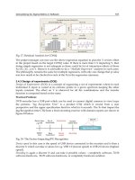
Fig. 30 Fatigue data (a) showing sequence effects for notched-specimen and smooth-
specimen simulations
(2024-T4 aluminum, K
f
= 2.0). Load histories A and B have a similar cyclic load pattern (dS
2
) but have
slightly
different initial transients (∆S
1
) with either (b) a tensile leading edge (first stress peak at +∆S
1
/2) or (c) a
compressive leading edge (first stress peak at -∆S
1
/2). The sequence effect on fatigue life (a) becomes more
pronounced as ∆S
2
smaller. Source: Ref 21
Ultimately, the fatigue analyst will be required to include and correlate a number of material, shape, processing, and load
factors in order to identify the critical locations within a part and to describe the local stress-strain response at those
critical locations. The ability to anticipate pertinent factors will greatly affect the final accuracy of the life prediction.
Load data gathering is one remaining topic that must be included in any discussion of fatigue. Reference 21 discusses
three load histories, suspension, transmission, and bracket vibration, that typify loads found in the ground vehicle
industry. Additionally, there are vastly different histories unique to other industries, like the so-called ground-air-ground
cycle in aeronautics. Without the ability to completely and accurately characterize anticipated and, occasionally,
unanticipated customer use and resultant loads, the analyst will not be able to predict accurately the suitability of a new or
revised design.
The last several years have seen a major change in the ability to gather customer or simulated customer load data. Testing
methods have progressed from bulky, multichannel analogue tape recorders (where it took days or weeks before results
were available) through portable frequency-modulated telemetry packages (where analysis could be performed
immediately at a remote site) to hand-held packages capable of data acquisition and analysis on board the test vehicle in
real time. Microelectronics is further reducing size and improving reliability to the point that data can be gathered from
within small, complex, moving, hostile assemblies, such as engines.
References cited in this section
6. R.C. Juvinall, Engineering Considerations of Stress, Strain and Strength, McGraw-Hill, 1967
7. N.E. D
owling, W.R. Brose, and W.K. Wilson, Notched Member Fatigue Life Predictions by the Local
Strain Approach, in Fatigue Under Complex Loading: Analyses and Experiments,
R.M. Wetzel, Ed.,
Society of Automotive Engineers, 1977
8. J.A. Graham, Ed., Fatigue Design Handbook, Society of Automotive Engineers, 1968
9. H.O. Fuchs and R.I. Stephens, Metal Fatigue in Engineering, John Wiley & Sons, 1980
10.
Special Publication P-109, in Proceedings of the SAE Fatigue Conference,
Society of Automotive
Engineers, 1982
11.
R.C. Rice, Ed., Fatigue Design Handbook, 2nd ed., Society of Automotive Engineers, 1988
12.
J.T. Ransom, Trans. ASM, Vol 46, 1954, p 1254-1269
13.
"Fatigue Properties," Technical Report, SAE J1099, Society of Automotive Engineers, 1977
14.
P.H. Wirsching and J.E. Kempert, A Fresh Look at Fatigue, Mach. Des., Vol 48 (No. 12), 1976, p 120-123
15.
L.E. Tucker, S.D. Downing, and L. Camillo, Accuracy of Simplified Fatigue Prediction Methods, in
Fatigue Under Complex Loading: Analyses and Experiments, R.
M. Wetzel, Ed., Society of Automotive
Engineers, 1977
16.
R.E. Peterson, Stress Concentration Design Factors, John Wiley & Sons, 1974
17.
R.J. Roark, Formulas for Stress and Strain, 4th ed., McGraw-Hill, 1965
18.
J.M. Potter, Spectrum Fatigue Life Predi
ctions for Typical Automotive Load Histories and Materials Using
the Sequence Accountable Fatigue Analysis, in
Fatigue Under Complex Loading: Analyses and
Experiments, R.M. Wetzel, Ed., Society of Automotive Engineers, 1977
19.
D.V. Nelson and H.O. Fuchs,
Predictions of Cumulative Fatigue Damage Using Condensed Load Histories,
in Fatigue Under Complex Loading: Analyses and Experiments,
R.M. Wetzel, Ed., Society of Automotive
Engineers, 1977
20.
S.D. Downing and D.F. Socie, Simple Rainflow Counting Algorithms, Int. J. Fatigue, Jan 1981
21.
D.F. Socie, "Fatigue Life Estimation Techniques," Technical Report 145, Electro General Corporation
Fatigue Resistance of Steels
Bruce Boardman, Deere and Company, Technical Center
References
1. R.W. Hertzberg, Deformation and Fracture Mechanics of Engineering Materials,
John Wiley & Sons,
1976
2. D.J. Wulpi, Understanding How Components Fail, American Society for Metals, 1985
3. Fatigue and Microstructure, in Proceeding of the ASM Materials Science Seminar, American
Society for
Metals, 1979
4. Metallic Materials and Elements for Aerospace Vehicle Structures, MIL-HDBK-5B,
Military
Standardization Handbook,, U.S. Department of Defense, 1987
5. Metallic Materials and Elements for Aerospace Vehicle Structures, Vol 1, MIL-HDBK-5B,
Military
Standardization Handbook, U.S. Department of Defense, Sept 1971, p 2-29
6. R.C. Juvinall, Engineering Considerations of Stress, Strain and Strength, McGraw-Hill, 1967
7. N.E. Dowling, W.R. Brose, and W.K. Wilson, Notched Member Fatig
ue Life Predictions by the Local
Strain Approach, in Fatigue Under Complex Loading: Analyses and Experiments,
R.M. Wetzel, Ed.,
Society of Automotive Engineers, 1977
8. J.A. Graham, Ed., Fatigue Design Handbook, Society of Automotive Engineers, 1968
9. H.O. Fuchs and R.I. Stephens, Metal Fatigue in Engineering, John Wiley & Sons, 1980
10. Special Publication P-109, in Proceedings of the SAE Fatigue Conference,
Society of Automotive
Engineers, 1982
11. R.C. Rice, Ed., Fatigue Design Handbook, 2nd ed., Society of Automotive Engineers, 1988
12. J.T. Ransom, Trans. ASM, Vol 46, 1954, p 1254-1269
13. "Fatigue Properties," Technical Report, SAE J1099, Society of Automotive Engineers, 1977
14. P.H. Wirsching and J.E. Kempert, A Fresh Look at Fatigue, Mach. Des., Vol 48 (No. 12), 1976, p 120-123
15.
L.E. Tucker, S.D. Downing, and L. Camillo, Accuracy of Simplified Fatigue Prediction Methods, in
Fatigue Under Complex Loading: Analyses and Experiments,
R.M. Wetzel, Ed., Society of Automotive
Engineers, 1977
16. R.E. Peterson, Stress Concentration Design Factors, John Wiley & Sons, 1974
17. R.J. Roark, Formulas for Stress and Strain, 4th ed., McGraw-Hill, 1965
18. J.M. Potter, Spectrum Fatigue Life Predictions for Typical Automotive Load Histories and Material
s
Using the Sequence Accountable Fatigue Analysis, in
Fatigue Under Complex Loading: Analyses and
Experiments, R.M. Wetzel, Ed., Society of Automotive Engineers, 1977
19. D.V. Nelson and H.O. Fuchs, Predictions of Cumulative Fatigue Damage Using Condensed
Load
Histories, in Fatigue Under Complex Loading: Analyses and Experiments,
R.M. Wetzel, Ed., Society of
Automotive Engineers, 1977
20. S.D. Downing and D.F. Socie, Simple Rainflow Counting Algorithms, Int. J. Fatigue, Jan 1981
21. D.F. Socie, "Fatigue Life Estimation Techniques," Technical Report 145, Electro General Corporation
Embrittlement of Steels
George F. Vander Voort, Carpenter Technology Corporation
Introduction
IRON-BASE ALLOYS are susceptible to a number of embrittlement phenomena. Some of these affect a wide range of
compositions, while others are specific to a rather narrow range of compositions. These problems promote brittle service
failures that may be catastrophic in nature or may reduce the useful service life of a component. This article reviews these
embrittlement problems and presents examples of their influence on mechanical properties. These problems arise from
compositional, processing, or service conditions, or combinations of these three conditions.
If the embrittlement occurs during processing at the mill, it may be detected during routine testing depending on the
degree of embrittlement and the nature of the testing program. The steelmaker is generally aware of the potential
problems that particular grades are susceptible to and will check the various well-known parameters that can promote
such problems. This starts with an examination of chemical composition, such as gas contents or impurity elements that
are known to cause problems. For example, in the melting of ingots for pressure vessels or rotors where temper
embrittlement is a potential problem, the selection of scrap for electric furnace melting is based on the scrap impurity
level, and every effort is made to keep residual levels of phosphorus, antimony, tin, and arsenic as low as possible.
Subsequent impact testing of coupons from the forgings is used to verify the initial toughness. Such information is
compared to specification requirements and historical data base information to maintain quality. Special melting
practices, such as vacuum carbon deoxidation, have also been adopted for critical composition control. Furthermore,
additional knowledge is obtained by surveillance testing and by postmortems on retired forgings.
However, not all potential problems can be detected, or prevented, at the mill. Some arise from handling or fabrication
problems. For example, low-carbon sheet steels that are not aluminum killed are roller leveled at the mill prior to
shipment to suppress the yield point and prevent strain-age embrittlement. However, if this steel is not formed within a
certain time period, the yield point will return, and discontinuous yielding may occur when the sheet is cold formed,
resulting in cosmetically damaging Lüders bands on the product. For this and other fabrication problems, postfabrication
inspection and testing programs must be properly planned and executed.
Service and environmental conditions can also cause a number of embrittlement problems. Engineers working with steel
components that are susceptible to such operating-induced problems must be aware of the potential problems and must
establish regular inspection programs to detect problems before they become critical. An excellent example of such
programs is the on-site, in situ examination of steam piping in electric power generation plants; these examinations make
extensive use of field metallography and replication to assess creep damage and predict remnant life.
Embrittlement of Steels
George F. Vander Voort, Carpenter Technology Corporation
Embrittlement of Iron
Before discussing the embrittlement of steels, this article will first examine the embrittlement of iron because the number
of such studies are few compared to those for steels. Grain-boundary segregation of elements such as oxygen, sulfur,
phosphorus, selenium, and tellurium is known to produce intergranular brittle fractures in iron at low temperatures.
Studies of the effects of such impurities in pure iron have been greatly aided by the development of Auger electron
spectroscopy (AES).
Intercrystalline fractures in iron at low temperatures occur when the carbon content is low. It has been assumed that the
absence of carbon is more important than the presence of embrittling grain-boundary impurities. However, impurities
must be present, and the role of carbon appears to be one of a competitor for grain-boundary sites when such impurities
are present.
Oxygen. A study of the toughness of iron-oxygen alloys found that intergranular embrittlement and a rise in impact
transition temperature in iron were produced by oxygen levels of 30 ppm or more (Ref 1). Figure 1 shows the Charpy V-
notch impact transition curves from this study for a series of iron-oxygen alloys with increasing oxygen contents (from 10
to 2700 ppm). However, the sulfur levels of the heats were rather high, from 30 to 54 ppm for the alloys shown in Fig. 1,
except for the 0.011% O heat, which had 16 ppm S. Because this work was conducted long before the introduction of
AES, the true nature of the embrittling grain-boundary element(s) is open to question.
Fig. 1 Charpy V-notch impact energy curves for iron-oxygen alloys with varying oxygen content. Source: Ref 1
Work on high-purity iron found intergranular brittleness at low test temperatures when specimens were quenched from
temperatures where carbon was in solution (Ref 2, 3). It was believed that this brittleness was due to oxygen. Lowering
the quench temperature reduced the embrittlement. Titanium additions were not found to be helpful in reducing the
intergranular embrittlement.
Reference 4 reviews the study from Ref 3 and reports on similar work performed in France that found that sulfur, not
oxygen, was the cause of the embrittlement. Tests were done using electrolytic iron containing 35 ppm S and a purified
iron containing less than 1 ppm S; each contained 2000 ppm O and varying carbon contents. The purified iron was found
to be much less brittle than the electrolytic iron (Fig. 2). At 10 ppm C, the purified iron was free of intergranular fracture;
the electrolytic iron fractured intergranularly below the ductile-to-brittle transition temperature (DBTT).
Fig. 2 Transition temperature, T
t
, versus carbon content for two different high-
purity irons, each containing
2000 ppm O. Source: Ref 4
Reference 5, on the other hand, shows Auger analysis of intergranular fractures of the pure iron specimen from Ref 2 that
contained 60 ppm S. Sulfur was not detected on the intergranular fracture, while carbon, nitrogen, and oxygen were. The
authors did state that the oxygen peak could possibly be due to oxygen contamination after fracture in the high vacuum
used for Auger work (fracture made inside the evacuated chamber).
It has been demonstrated that large variations in oxygen content have no influence on the brittleness of iron (Ref 6). The
Charpy U-notch transition temperatures of electrolytic iron and high-purity iron with varying oxygen and carbon contents
were determined, as in Ref 4. Figure 3 shows that the DBTTs for these two irons were constant over a wide range of
oxygen contents (1 to 2000 ppm). The DBTT of the electrolytic iron (210 °C, or 410 °F) was consistently much higher
than that of the high-purity iron (20 °C, or 70 °F). Also, fractures for the electrolytic iron specimens in the brittle range
were fully intergranular, whereas those for the high-purity iron were by cleavage. Carbon and sulfur contents were 30 and
35 ppm, respectively, for the electrolytic iron and 10 and less than 3 ppm, respectively, for the high-purity iron.
Manganese contents were 12 ppm for the electrolytic iron and less than 0.5 ppm for the high-purity iron, too little to tie up
the sulfur completely in the electrolytic iron. Figure 4 shows the results when carbon and oxygen were both varied. When
the carbon level was increased to 30 ppm, there was a large improvement in the DBTT, irrespective of the oxygen level.
This study also demonstrated that the addition of elements that form sulfide precipitates improved the DBTT.
Fig. 3 Ductile-to-brittle transition temperatures (from tests using Charpy U-
notch specimens) as a function of
oxygen content for a decarburized electrolytic iron and a high-purity iron with 10 ppm C. Source: Ref 6
Fig. 4 Ductile-to-brittle transition temperatures of high-purity iron as a function
of carbon content and oxygen
content. Source: Ref 6
On the other hand, a study using irons with less than 2 ppm S and 0.5 ppm C and Auger analysis demonstrated oxygen
grain-boundary enrichment of intergranular fractures broken by impact within the AES chamber (Ref 7). Segregation of
elements such as sulfur, phosphorus, and nitrogen was not observed on the fracture, but oxygen was detected. For a
specimen with a bulk oxygen content of 430 at. ppm, there were two monolayers of oxygen at the intergranular fracture
surface. Carbon was not present at the fracture surface, consistent with the very low bulk carbon content. Another
specimen with 235 at. ppm O exhibited about 15% cleavage fracture, along with areas that were predominantly
intergranular. The study found that for the material with higher oxygen content, quenching specimens from temperatures
of 1103 and 1123 °C (2017 and 2053 °F), near the solubility limit, gave predominantly intergranular low-temperature
fractures. When the temperature was lowered from 973 to 773 °C (1783 to 1423 °F), below the solubility limit, the
amount of intergranular fracture decreased. Also, if the specimen was slow cooled from temperatures near the solubility
limit, low-temperature fractures were fully by cleavage. Therefore, the study concluded that intergranular brittle fracture
of iron was due to the oxygen in solution.
Sulfur. The embrittlement of iron by sulfur has been demonstrated by several authors. Prior to Auger analysis, such
results were assumed, but without direct proof. Auger work has, indeed, confirmed that sulfur is a potent embrittler of
iron, even at bulk levels as low as 10 ppm. Furthermore, the displacement of sulfur on the grain boundaries when carbon
is added has been proved by Auger analysis. Low-temperature impact tests performed on three heats of relatively pure
iron obtained intergranular fractures, depending on the heat treatment used (Ref. 8). Sulfur contents ranged from 14 to
100 ppm, carbon contents from less than 10 to 70 ppm, and oxygen contents from 8 to 420 ppm. Auger analysis revealed
heavy segregation of sulfur to the grain boundaries. No clear evidence of oxygen on the intergranular fractures was
obtained.
Other studies have shown the detrimental influence of small sulfur additions (Ref 9, 10). Figure 5, from these studies,
shows the DBTT as a function of bulk sulfur content (
≤
60 ppm) and the beneficial influence of carbon additions (
≤
10 to
30 ppm) for iron containing 2000 ppm O. For less than or equal to 10 ppm C, the transition temperature increased from 0
to over 600 °C (30 to >1110 °F) with increasing sulfur content. However, with 25 of 30 ppm C, the influence of sulfur
was small. Also demonstrated was the scavenging influence of a 0.5% Al addition, which suppressed embrittlement
(constant DBTT) for the full range of sulfur (
≤
60 ppm) tested.
Fig. 5
Influence of sulfur on the transition temperature of purified iron containing 2000 ppm O, and the
influence of carbon content on sulfur embrittlement. Increasing carbon content has the bene
ficial effect of
decreasing sulfur embrittlement. Source: Ref 9, 10
Selenium and tellurium are similar to sulfur and are potential embrittlers of pure iron. One study (Ref 10) showed
that they do cause embrittlement, but to a lesser degree than sulfur (Fig. 6). In this work, the carbon content was less than
10 ppm, and 2000 ppm O was present. Although selenium and tellurium had less influence on the DBTT, these two
elements reduced the absorbed energy values much more than did sulfur. Therefore, in terms of impact energy, the
elements can be placed in order of increasing influence as follows: sulfur, selenium, and tellurium. Others have also
reported the embrittlement of Fe-0.04% C by 0.02% Te (Ref 11).
Fig. 6
Influence of sulfur, tellurium, and selenium on the transition temperature of purified iron containing up
to 10 ppm carbon and approximately 2000 ppm O. Source: Ref 10
Other Impurity Elements. Phosphorus has also been reported to embrittle pure iron (Ref 12, 13). However, both of
these studies used materials with a significant sulfur content, and they were performed prior to the development of Auger
analysis. However, radioactive tracer analysis demonstrated the segregation of phosphorus at the grain boundaries of an
Fe-0.09% P alloy (Ref 12). Phosphorus was reported to be 50 times as prevalent at the grain boundaries as in the grain
interiors. Phosphorus does substantially increase the strength of ferrite. Again, the addition of carbon was shown to
reduce the influence of phosphorus on embrittlement.
Researchers have also studied phosphorus segregation in pure iron (Ref 14). Again, the specimens contained a significant
amount of sulfur, but mechanical properties were not determined. However, a small amount of manganese was present
that should precipitate the sulfur as a sulfide. The carbon content was reduced to below 10 ppm. Specimens were
austenitized, water quenched, tempered at 850 °C (1560 °F) for 1 h, and then furnace cooled to the aging temperature.
Specimens were fractured within the Auger chamber. Phosphorus was observed on the surface of intergranular fractures,
but not on cleavage fractures. Auger analysis showed that the amount of phosphorus on the intergranular fractures
increased with bulk phosphorus content. Also, as the aging temperature decreased, the grain-boundary phosphorus content
increased, and the fracture became more intergranular. When carbon was added (
≤
80 ppm), the grain-boundary
phosphorus concentration decreased. A deep-drawing steel containing 7 ppm C, 310 ppm P, and 0.36% Mn fractured
intergranularly in the drawing direction, and phosphorus was detected on the grain boundaries (Ref 14). Similar steels
with 14 ppm C, 80 ppm P, and 0.38% Mn did not fracture during deep drawing.
A study of the embrittlement of iron by phosphorus, phosphorus and sulfur, and antimony and sulfur demonstrated that
the embrittlement was different from that of temper embrittlement in that it was not reversible (Ref 15). Segregation
occurred at all temperatures in ferrite but was negligible or limited in austenite. Quenching from the austenite region
produced specimens that fractured by cleavage. When quenched from the two-phase region, fractures did exhibit
phosphorus at the grain boundaries. When an Fe-0.2P alloy was furnace cooled from the austenite region, the fracture
surface exhibited a layer of nearly pure phosphorus at the grain boundary with a thickness of 1 to 1.5 nm (10 to 15
A
o
).
The ternary alloys containing sulfur exhibited DBTTs of about 350 °C (660 °F). The study concluded that sulfur, even at
much lower concentrations than phosphorus, is a more potent embrittler of iron.
Metalloids such as phosphorus, arsenic, antimony, and tin do not produce embrittlement of pure iron containing minor
amounts of carbon in the same manner as sulfur, although they do in alloy steels (Ref 16). It has been demonstrated that
such elements produce embrittlement of carbide/ferrite and surrounding ferrite/ferrite interfaces (Ref 17). This appears to
be a nonequilibrium segregation problem, however.
The influence of tin on high-purity iron and low-carbon steel has been examined (Ref 18). Detailed chemical analyses of
the pure iron specimens used were not given in the study, although it was stated that the base metal had a carbon content
of 20 ppm and an oxygen content of 400 ppm. The addition of 0.5% Sn to the pure iron reduced the impact strength in the
ductile region to such a degree that the absorbed energy was constant up to 70 °C (160 °F). Specimens water quenched
from 650 °C (1200 °F) exhibited impact results similar to those of tin-free pure iron, while slowly cooled specimens were
embrittled. The addition of 0.15% C to the Fe-0.5Sn alloy did reduce the embrittling influence of tin, and the alloy had
better toughness than the pure iron specimen when water quenched from 650 °C (1200 °F). The addition of 0.15% P to
the Fe-0.5Sn-0.15C alloy raised the DBTT about 20 °C (36 °F) and lowered the upper-shelf energy when water quenched
from 650 °C (1200 °F). The examination of fractured specimens showed a changed from transgranular cleavage to
intergranular fracture as the tin content increased, particularly for the slowly cooled specimens.
This survey of the influence of impurities on the embrittlement of pure iron has demonstrated that the design of
experiments and the interpretation of results are difficult. Many of the early studies did not recognize the significance of
relatively minor amounts of sulfur in the high-purity irons used. It is clear that Auger analysis is required to determine the
embrittling species. When sulfur is present in the absence of sulfide-forming elements, it has a dominating influence on
properties and behavior. The addition of carbon above about 10 ppm will reduce or eliminate embrittlement effects.
References cited in this section
1. W.P. Rees and B.E. Hopkins, Intergranular Brittleness in Iron-Oxygen Alloys, J. Iron Steel Inst.,
Vol 172,
Dec 1952, p 403-409
2. C.J. McMahon, Jr., Intergranular Brittleness in Iron, Acta Metall., Vol 14, July 1966, p 839-845
3. J.R. Rellick and C.J. McMahon, Jr., The Elimination of Oxygen-Induced Intergranular Br
ittleness in Iron by
Addition of Scavengers, Metall. Trans., Vol 1, April 1970, p 929-937
4. P. Jolly, Discussion of "The Elimination of Oxygen-
Induced Intergranular Brittleness in Iron by Addition of
Scavengers," Metall. Trans., Vol 2, Jan 1971, p 341-342
5. J.R. Rellick et al., Further Information on Oxygen Induced Intergranular Brittleness in Iron, Metall. Trans.,
Vol 2, Jan 1971, p 342-343
6. C. Pichard et al., The Influence of Oxygen and Sulfur on the Intergranular Brittleness of Iron,
Metall.
Trans. A, Vol 7A, Dec 1976, p 1811-1815
7. A. Kumar and V. Raman, Low Temperature Intergranular Brittleness of Iron, Acta Metall.,
Vol 29, 1981, p
1131-1139
8. B.D. Powell et al., A Study of Intergranular Fracture in Iron Using Auger Spectroscopy, Metall. Trans.,
Vol
4, Oct 1973, p 2357-2361
9. P. Jolly and C. Goux, Influence of Certain Impurities on Intercrystalline Embrittlement of Iron,
Mem. Sci.
Rev. Met., Vol 66 (No. 9), 1969, p 605-617
10.
C. Pichard et al., Influence of Sulfur Type Metalloid Impuritie
s on the Intercrystalline Embrittlement of
Pure Iron, Mem. Sci. Rev. Met., Vol 70 (No. 1), 1973, p 13-22
11.
J.R. Rellick et al., The effect of Telurium on Intergranular Cohesion in Iron, Metall. Trans.,
Vol 2, May
1971, p 1492-1494
12.
M.C. Inman and H.R. Tipler, Grain-Boundary Segregation of Phosphorus in an Iron-
Phosphorus Alloy and
the Effect Upon Mechanical Properties, Acta Metall., Vol 6, Feb 1958, p 73-84
13.
B.E. Hopkins and H.R. Tipler, The Effect of Phosphorus on the Tensile and Notch-Impact Pr
operties of
High-Purity Iron and Iron-Carbon Alloys, J. Iron Steel Inst., Vol 188, March 1958, p 218-237
14.
H. Erhart and H.J. Grabke, Equilibrium Segregation of Phosphorus at Grain Boundaries of Fe-P, Fe-C-
P,
Fe-Cr-P, and Fe-Cr-C-P Alloys, Met. Sci., Vol 15, Sept 1981, p 401-408
15.
P.V. Ramasubramanian and D.F. Stein, An Investigation of Grain-Boundary Embrittlement in Fe-P, Fe-P-
S,
and Fe-Sb-S Alloys, Metall. Trans., Vol 4, July 1973, p 1735-1742
16.
C.J. McMahon, Jr., Strength of Grain Boundaries in Iron-Base Alloys, in
Grain Boundaries in Engineering
Materials, Claitor, 1975, p 525-552
17.
J.R. Rellick and C.J. McMahon, Jr., Intergranular Embrittlement of Iron-
Carbon Alloys by Impurities,
Metall. Trans., Vol 5, Nov 1974, p 2439-2450
18.
C.J. Thwaites and S.K. Chatterjee, Effect of Tin on the Impact Behavior of Alloys Based on High-
Purity
Iron and Mild Steel, J. Iron Steel Inst., Vol 210, Aug 1972, p 581-587
Embrittlement of Steels
George F. Vander Voort, Carpenter Technology Corporation
Embrittlement in Carbon Steels and Alloy Steels
Several forms of embrittlement can occur during thermal treatment or elevated-temperature service of carbon and alloy
steels. These forms of embrittlement (and the types of steel that some forms specifically affect) are:
• Blue brittleness (carbon steels)
• Quench-age embrittlement (low-carbon steels)
• Strain-age embrittlement (low-carbon steels)
• Aluminum nitride embrittlement (carbon and alloy steels
• Graphitization (carbon and alloy steels)
Blue Brittleness
Carbon steels generally exhibit an increase in strength and a reduction of ductility and toughness at temperatures around
300 °C (570 °F). Because such temperatures produce a bluish temper color on the surface of the specimen, this problem
has been called blue brittleness (Ref 19, 20, 21, 22). It is generally believed that blue brittleness is an accelerated form of
strain-age embrittlement. Deformation in the blue-heat range followed by testing at room temperature produces an
increase in strength that is greater than when the deformation is performed at ambient temperature. Blue brittleness can be
eliminated if elements that tie up nitrogen are added to the steel, for example, aluminum or titanium.
Quench-Age Embrittlement
If a carbon steel is heated to a temperature slightly below its lower critical temperature and then quenched, it will become
harder and stronger but less ductile (Ref 23, 24, 25, 26, 27, 28). This problem has been called quench aging or quench-age
embrittlement. The degree of embrittlement is a function of time at the aging temperature. Aging at room temperature
requires several weeks to reach maximum embrittlement. Lowering the quenching temperature reduces the degree of
embrittlement. Quenching from temperatures below about 560 °C (1040 °F) does not produce quench-age embrittlement.
Carbon steels with a carbon content of 0.04 to 0.12% appear to be most susceptible to this problem.
Quench aging is caused by the precipitation of carbide and/or nitride from solid solution. One study has reviewed the
quench aging of iron-nitrogen, iron-carbon, and iron-carbon-nitrogen alloys (Ref 25). Figure 7 shows the change in
hardness, interparticle spacing, and practice size of precipitates in an Fe-0.02N alloy quenched from 500 °C (930 °F) and
aged at 60 °C (140 °F) up to 500 h. The precipitates grew from about 30 nm (300
A
o
) in diameter after 2 h to about 80 nm
(800
A
o
) in diameter after 500 h. With aging, the hardness increased rapidly to about 150 HV after 10-h aging at 60 °C
(140 °F) and then decreased to about 120 HV with aging to 500 h.
Fig. 7
Influence of aging time at 60 °C (140 °F) after quenching from 500 °C (930 °F) on the hardness, particle
size, and interparticle spacing for an Fe-0.02N alloy. Source: Ref 25
Low-Carbon Steels. For low-carbon steels, quench aging is due mainly to carbon because the nitrogen level is usually
too low to have a substantial effect. Results for a rimming steel containing 0.03% C (Fig. 8) show the increase in hardness
with aging time at 60 °C (140 °F) for specimens quenched from 725 °C (1335 °F). The tensile strength increased rapidly
to a maximum value after 10 h at 60 °C (140 °F) and then decreased slowly with further aging. The yield strength also
increased rapidly and reached a maximum in about the same time but remained constant with continued aging. The
elongation and reduction of area decreased as the strength increased; they reached a minimum after 10 h and then
increased somewhat with continued aging.
Fig. 8
Influence of aging time at 60 °C (140 °F) after quenching from 725 °C (1335 °F) on the tensile
properties of an Fe-0.03C rimm
ing alloy. (a) Tensile and yield strength. (b) Elongation and reduction in area.
Source: Ref 25
Iron-Nitrogen and Iron-Carbon Alloys. For iron-nitrogen alloys, two types of nitrides can precipitate during
quench aging:
• Face-centered cubic (fcc) Fe
4
N platelets form at high temperatures and generally are found at grain
boundaries
• Body-centered cubic (bcc) Fe
16
N
2
nitrides
with a circular disk shape precipitate at low temperature on
dislocations
This latter type of nitride causes strengthening during quench in iron-nitrogen alloys (Ref 25). Iron-carbon alloys also
have two types of carbides that can form during quench aging. Cementite forms at high temperatures, and a low-
temperature carbide that is identical in morphology and habit to Fe
16
N
2
and may be isomorphous with it can also form.
With aging, the low-temperature carbide will gradually be replaced by Fe
3
C (Ref 25). The phase changes during aging of
iron-nitrogen and iron-carbide quench aged steels are discussed in the literature (Ref 28).
Strain-Age Embrittlement
Strain aging occurs in low-carbon steels deformed certain amounts and then aged, which produces an increase in strength
and hardness but a loss in ductility (Ref 25, 26, 27, 29, 30, 31, 32, 33, 34). The degree of deformation, or cold work, is
important. Generally, about a 15% reduction in thickness provides the maximum effect. The resulting brittleness varies
with the aging temperature and time. Aging at room temperature is very slow, requiring several months to obtain
maximum embrittlement. As the aging temperature is increased, the time for maximum embrittlement decreases. Certain
coating treatments, such as hot dip galvanizing, can produce a high degree of embrittlement in areas that were cold
worked the critical amount; this can lead to brittle fractures. To prevent this problem, the part can be annealed before
galvanizing. Alternatively, the use of sheet steels containing elements that tie up nitrogen, for example, aluminum,
titanium, zirconium, vanadium, or boron, will prevent strain-age embrittlement.
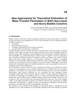
Strain aging may also lead to stretcher-strain marks (Lüders bands) on cold-formed low-carbon sheet steel components.
These marks are cosmetic defects, rather than cracks, but their presence on formed parts is unacceptable (Fig. 9). During
tensile loading, sheet steel that is susceptible to this defect will exhibit nonuniform yielding followed by uniform
elongation. The elongation at maximum load and the total elongation are reduced, decreasing cold formability. In a
nonaluminum-killed sheet steel, a small amount of deformation, typically 1% reduction, will suppress the yield point for
several months. This process is referred to as roller levelling or temper rolling (Ref 31). This process is more effective in
eliminating the sharp yield point and preventing strain aging than stretching the steel through the Lüders strain, which
requires about 4 to 6% reduction. However, if the material is not formed within the safe period, discontinuous yielding
will eventually return and impair formability.
Fig. 9 Example of stretcher-strain marks (Lüders bands) on a cold-formed steel part
Results of one study illustrate the influence of strain aging on mechanical properties (Ref 32). Three steels made by
different processes were evaluated: Steel A, silicon and aluminum deoxidized steel; Steel B, capped open hearth steel; and
Steel C, capped Bessemer steel. Steel C had the highest nitrogen content. Steels B and C had low aluminum contents,
while steel A had sufficient aluminum to tie up the nitrogen. Strips of each were normalized and loaded in tension to a
permanent strain of 10%. The strips were held at 25, 230, 480, and 650 °C (75, 450, 900, and 1200 °F) for various lengths
of time (
≤
25,000 h at 25 and 230 °C, or 75 and 450 °F;
≤
10 h at 480 °C, or 900 °F; and 2 h at 650 °C, or 1200 °F).
Hardness, tensile properties, and impact properties (half-width Charpy V-notch specimens) were determined at different
aging times.
Figure 10 shows the impact test results for steels A, B, and C strained 10% in tension and aged at room temperature up to
25,000 h. The impact curves are shifted with aging at room temperature for all three steels; steel A exhibits the best aged
toughness, and steel C the poorest. Figure 11 shows the increase in hardness for steels A, B, and C aged for times up to
25,000 h at 25 °C (75 °F) and 230 °C (450 °F). Room-temperature aging produced a gradual increase in hardness with
time. The maximum hardness was about the same and was reached quickest by steel C and slowest by steel A. The
hardness increase with aging at 230 °C (450 °F) was constant for steel A and slowly decreased with aging for steels B and
C.
Fig. 10 Influence of straining in tension and aging at 24 °C (75 °F) on the Charpy V-
notch (half width) impact
strength for three steels. (a) Steel A, silicon and aluminum
killed, 0.25% C with 0.013% Al and 0.011% N. (b)
Steel B, capped open hearth steel, 0.07% C with 0.005% Al and 0.005% N. (c) Steel C, capped Bessemer steel,
0.08% C with 0.006% Al and 0.016% N. All three steels were strained 10% and aged. Source: Ref 32
Fig. 11 Increase in hardness for steels A, B, and C from Fig. 10 after straining in tension (10%) and agin
g at
24 and 230 °C (75 and 450 °F) for up to 25,000 h. Source: Ref 32
In low-carbon steels, strain aging is caused chiefly by the presence of interstitial solutes (carbon and nitrogen), although
hydrogen is known to produce a lesser effect at low temperatures. These interstitial solutes have high diffusion
coefficients in iron and high interaction energies with dislocations. The change in mechanical properties of low-carbon
rimming steels with different carbon and nitrogen contents that were prestrained 4% and aged various times at 60 °C (140
°F) has been demonstrated (Fig. 12) (Ref 34). This work clearly demonstrates the detrimental influence of higher carbon
and nitrogen contents on strain aging. The solubilities of carbon and nitrogen in iron are quite different. Nitrogen
solubility is high in the temperature range where rapid precipitation occurs; the solubility of carbon, in equilibrium with
cementite, is very low. Therefore, strain aging that is due to carbon at temperatures below 100 °C (210 °F) is
insignificant. However, above 100 °C (210 °F), ε carbide can redissolve and produce substantial strain aging (Ref 35).
Strain aging attributable to nitrogen is caused by nitrogen that is not tied up with strong nitride formers, for example,
aluminum, titanium, zirconium, vanadium, or boron.
Fig. 12
Influence of grain size and aging time at 60 °C (140 °F) on the mechanical property changes caused by
strain aging. A 0.038C-0.0042N-
0.001Al steel was quenched from 200 °C (390 °F), prestrained 4%, and tested
after different aging times. Grain sizes, in grains/mm
2
(ASTM number), were: specimen 1, 50 (2.7); specimen
2, 195 (4.7); specimen 5, 1850 (7.9). Source: Ref 34
Dynamic Strain Aging. Strain aging can also occur dynamically, that is, aging occurs simultaneously with straining.
In this case, the effective strain rate, that is, the dislocation velocity, controls the extent of aging of a particular steel. For
normal tensile strain rates, dynamic strain aging occurs in the temperature range of 100 to 300 °C (210 to 570 °F) (which
includes temperatures at which blue brittleness occurs). If the interstitial solute content is substantial, dynamic strain
aging may be observed at room temperature. At very high strain rates, as in impact testing, dynamic strain aging is
observed at temperatures above 400 °C (750 °F), up to about 670 °C (1240 °F). Reference 33 presents dynamic strain
aging results for five carbon steels. Carbon and nitrogen are, again, the most important elements in dynamic strain aging.
Nitrogen is more important than carbon because of the lower solubility of carbon.
Aluminum Nitride Embrittlement
It is well known that aluminum nitride precipitation in aluminum-killed steels can cause embrittlement and fracture.
Several types of problems due to aluminum nitride precipitation have been observed: intergranular fractures in castings
(Ref 36, 37, 38, 39, 40, 41, 42, 43), panel cracking in ingots (Ref 44, 45, 46, 47), and reduced hot ductility (Ref 48, 49,
50, 51, 52, 53).
Intergranular fracture in castings, in both the as-cast and heat-treated conditions, have been sporadically observed
for many years. The fractures occur at the primary austenite grain boundaries formed during solidification. In as-cast
specimens, ferrite films are generally observed at these grain boundaries. The incidence of such cracking has been shown
to increase with increases in aluminum and nitrogen contents and with slower cooling rates after casting.
It has been claimed that additions of titanium, zirconium, boron, sulfur, molybdenum, or copper decrease the tendency for
cracking (Ref 36). The cooling rate between 1150 and 700 °C (2100 and 1290 °F) is important in controlling the amount
of aluminum nitride precipitation. The minimum amount of aluminum nitride required to produce intergranular fracture is
lower for alloy steels than for plain carbon steels (0.002 versus 0.004%) (Ref 37). Minimizing the nitrogen content, using
the lowest possible amount of aluminum for deoxidation, and increasing the cooling rate after solidification are
recommended, and it has been demonstrated that cracking can be prevented by deoxidizing with titanium or zirconium or
by combined titanium and aluminum (Ref 37).
Some researchers have claimed that higher levels of phosphorus and sulfur reduce the susceptibility to aluminum nitride
intergranular fractures (Ref 38). Nitrogen content has been shown to be more important than aluminum content because
aluminum is always present in amounts greater than that required to tie up all of the nitrogen (Ref 41). Higher aluminum
contents do, however, increase the solubility temperature of aluminum nitride and provide an additional driving force for
precipitation.
Aluminum nitride is known to precipitate with one of two morphologies: plates or dendritic arrays (Ref 38). The dendritic
form of aluminum nitride found on the intergranular fracture surfaces of aluminum nitride embrittled castings precipitates
from the liquid near the conclusion of solidification (Ref 42). These aluminum nitride dendrites may be nucleation sites
for platelike aluminum nitride that precipitates after solidification. The platelike aluminum nitride produces that small,
shiny fracture surface facets that are generally observed (Ref 43).
Panel Cracking. Panel cracks are longitudinally oriented surface cracks on the side face of an ingot that generally form
near the center of the face and can extend to the midradius of the ingot (Ref 44). Such cracks can occur on more than one
ingot face and can run the entire length of the ingot. Panel cracks are observed in aluminum-killed steel ingots,
particularly those with 0.4 to 0.7% C (plain carbon steels) or those with somewhat lower carbon contents for alloy steel
ingots. These carbon contents lead to ferrite grain-boundary network films with predominantly pearlitic matrix structures.
The susceptibility to panel cracking varies with melt practice: electric arc furnace steels are most prone; basic open
hearth, basic oxygen furnace, and acid open hearth steels are less prone. Large ingots are more susceptible than small
ingots. Stripping of the ingot at as hot a temperature as possible reduces susceptibility. Again, aluminum and nitrogen
contents are very important. Panel cracking is not observed with less than 0.015% Al but occurs with increasing
frequency with increasing aluminum content above this level. Also, for a given aluminum content, increasing the nitrogen
above 0.005% increases panel cracking. Crack surfaces are oxidized but not decarburized. Because the intergranular
cracks generally propagate along ferrite/pearlite interfaces, it has been suggested that cracking occurs at relatively low
temperatures, probably below 850 °C (1560 °F) (Ref 44).
A statistical study of panel cracking found that the only significant variable was the level of the aluminum addition (Ref
45). It was suggested that cracking began internally and propagated to the surface because of cooling-induced stresses. In
a study of panel cracking in two alloy steels, one containing 0.025% Al and 0.008% N and the other having 0.004% Al
and 0.006% N, the former exhibited panel cracking, and the latter did not. Additions of aluminum and titanium to the
crack-prone steel composition resulted in the elimination of grain-boundary ferrite networks and freedom from cracking
(Ref 46).
A statistical study of panel cracking in low-carbon plate steels found that the steels did not exhibit grain-boundary ferrite
networks, but rolled bloom surfaces were heavily cracked in some cases. Some of the observations in this study differ
from those of other authors who have studied panel cracking. However, the statistical analysis showed that cracking
increased with aluminum content and track time (time between ingot stripping and charging into the soaking pit).
Cracking was minimized by holding the aluminum contents to 0.030% or less (Ref 47).
Reduced Hot Ductility. Numerous studies have demonstrated that increasing aluminum and nitrogen contents degrade
hot ductility; this influence is most pronounced in the temperature range where aluminum nitride precipitation is greatest
(Ref 48, 49, 50, 51, 52, 53). One author found that 3.4% Ni raised the solution temperature of aluminum nitride in En 36
alloy steel by about 100 °C (210 °F) compared to plain carbon steels with the same aluminum and nitrogen levels (Ref
48). Another study evaluated the hot ductility of chromium-molybdenum-vanadium turbine rotor steels with 0.002 to
0.066% Al and 0.007 to 0.014% N. This study showed that nitrogen and residuals (copper, tin, antimony, and arsenic)
reduced the hot ductility. The addition of titanium and/or boron improved the hot ductility in the test range (800 to 1000
°C, or 1470 to 1830 °F) where high nitrogen contents were detrimental (Ref 49).
In hot ductility tests on carbon-manganese steels containing 0.032 to 0.073% Al and 0.0073 to 0.0105% N, aluminum
nitride was found to reduce deformability and increase the resistance to the deformation of austenite. These trends were
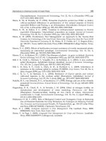
enhanced as the aluminum nitride particle size decreased (Ref 50). Other hot ductility tests on low-carbon steels also
showed a large decrease in hot ductility because of aluminum nitride precipitation, depending on the volume fraction and
size of the precipitates (Ref 51). Five steels were tested containing different levels of soluble aluminum (aluminum not
tied up with oxygen) and with nitrogen present as aluminum nitride. Figure 13 shows the reduction in area for hot tensile
tests over a range of temperatures for five steels. Steels A and B showed a large decrease in percent reduction in area with
increasing temperature; however, steel C did not exhibit such embrittlement. The difference between steels A, B, and C,
which all had high levels of nitrogen in the form of aluminum nitride, was the particle size. The smaller aluminum nitride
particles in steels A and B were detrimental to hot ductility, while the larger particles in steel C did not cause
embrittlement; this agrees with the findings in Ref 50. Steel E contained 0.06% Ti and exhibited the best hot ductility.
Composition
Particle size
Low-carbon steel
N, ppm
(a)
Ti, %
nm
A
o
Curve A 80 . . . 90
900
Curve B 70 . . . 80
800
Curve C 72 . . . 210
2100
Curve D 2 . . .
(b)
(b)
Curve E 1 0.06
(b)
(b)
(a)
As AIN.
(b)
No data
Fig. 13 Elevated-
temperature tensile test results for five plain carbon steels containing various amounts of
aluminum nitride. The nitrogen content (in ppm) of the steels in the form of aluminum nitride
was: A, 80; B,
70; C, 72; D, 2; E, 1. Source: Ref 51
An evaluation of the hot ductility of low-carbon killed steels found a substantial reduction in fracture strain between 700
and 800 °C (1290 and 1470 °F). This reduction was most pronounced between 750 and 775 °C (1380 and 1425 °F), where
ferrite formed along the prior-austenite grain boundaries. The intergranular fracture surfaces exhibited aluminum nitride
and manganese sulfide precipitates (Ref 53).
Hot ductility is also impaired by high residual impurity contents, chiefly those of copper and tin (Ref 54, 55, 56, 57, 58,
59, 60). Examinations of forging and rolling defects have frequently revealed concentrations of elemental copper, high
levels of copper and tin, or copper in the scale. Tin residual levels are normally much lower than copper residual levels,
but there appears to be a synergistic effect between copper and tin that enhances embrittlement (Ref 54). An examination
of longitudinal cracks in medium- and high-carbon steels found that cracking occurred between 700 and 500 °C (1290
and 930 °F) and depended on high copper and tin contents. Aluminum was not added to these steels, but grain-boundary
ferrite networks were present. The copper and tin were segregated to the ferrite networks (Ref 55).
Nickel, copper, tin, antimony, and arsenic often become enriched in the subscale layer at the surface of steels heated for
forging and rolling in oxidizing atmospheres. It has been shown that tin, antimony, and arsenic residuals alter the
solubility of copper in austenite during high-temperature soaking. Because the hot-working temperature is usually above
the melting point of elemental copper, liquid copper is produced that will penetrate the austenite grain boundaries and
cause cracking by liquid metal embrittlement. Nickel and molybdenum concentrate with copper and raise the melting
point of copper; tin, antimony, and arsenic also concentrate at the scale/metal interface and lower the melting point of
copper. If copper is not present, tin, antimony, and arsenic have little detrimental effect on hot workability (Ref 56).
It has been shown that tin reduces the solubility of copper in austenite, which is probably more important than its
influence on the melting point of copper (Ref 56). Tin reduces the solubility of copper in austenite by a factor of three;
therefore, when tin is present, molten copper can form at the surface at lower bulk copper contents. Nickel reduces
copper-induced hot shortness, manganese slightly increases hot shortness, arsenic slightly more detrimental than
manganese, and tin and antimony are extremely detrimental to copper-induced hot shortness (Ref 58). Chromium
decreases the solubility of copper in austenite and increases the susceptibility to copper-induced hot shortness, although
its influence is small (Ref 59).
Graphitization
In the early 1940s, several failures of welded joints in high-pressure steam lines occurred because of graphite formation in
the region of the weld heat-affected zone that had been heated during welding to the critical temperature of the steel used
(Ref 61, 62, 63, 64, 65). Extensive surveys of carbon and carbon-molybdenum steel specimens removed from various
types of petroleum refining equipment revealed graphite in about one-third of the 554 specimens examined (Ref 61, 64).
In most cases, graphite formation did not occur until about 40,000 h or more at temperatures from 455 to 595 °C (850 to
1100 °F). Aluminum-killed carbon steels were susceptible, but silicon-killed or low-aluminum killed steels were not. The
C-0.5Mo steels were more resistant to graphitization than carbon steels, but they were similarly influenced by the nature
of the deoxidation practice. Chromium additions and stress relieving at 650 °C (1200 °F) both retarded graphitization.
An examination of the graphitization susceptibility of a number of alloy steels showed that chromium-molybdenum steels
used for steam piping, either annealed or normalized, were resistant to graphitization. Nickel and nickel-molybdenum
steels did graphite during high-temperature exposure. Chromium-bearing steels did not graphitize and appeared to be
quite stable (Ref 65).
The deoxidation practice used in making the steels is the most important parameter influencing graphitization. High levels
of aluminum deoxidation strongly promote graphitization for both carbon and carbon-molybdenum steels used for steam
lines. While nitrogen appears to retard graphitization, high levels of aluminum remove nitrogen and thus promote
graphitization (Ref 66). Molybdenum additions (0.5%) help stabilize cementite but do not fully offset the influence of
high aluminum additions. Manganese and silicon both affect graphitization, but their influence is small at the levels used
in these alloys. Chromium appears to be the best alloy addition for stabilizing carbides.
Tensile tests of affected steam piping indicate that the graphite present did not affect the tensile strength. Charpy V-notch
impact strength, however, was reduced substantially. Localized graphitization near a welded joint appears to be much
more damaging to pipe behavior than general, uniform graphitization. The localized graphitization apparently produces
notches that concentrate stress and reduce load-bearing capability.
References cited in this section
19.
R.L. Kenyon and R.S. Burns, Testing Shee
ts for Blue Brittleness and Stability Against Changes Due to
Aging, Proc. ASTM, Vol 34, 1934, p 48-58
20.
E.O. Hall, The Deformation of Low-Carbon Steel in the Blue-Brittle Range, J. Iron Steel Inst.,
Vol 170,
April 1952, p 331-336
21.
G. Mima and F. Inoko, A Study of the Blue-
Brittle Behavior of a Mild Steel in Torsional Deformation,
Trans. JIM, Vol 10, May 1969, p 227-231
22.
T. Takeyama and H. Takahashi, Strength and Dislocation Structures of α-Irons Deformed in the Blue-
Brittleness Temperature Range, Trans. ISIJ, Vol 13, 1973, p 293-302
23.
A.L. Tsou et al., The Quench-Aging of Iron, J. Iron Steel Inst., Vol 172, Oct 1952, p 163-171
24.
T.C. Lindley and C.E. Richards, The Effect of Quench-Aging on the Cleavage Fracture of a Low-
Carbon
Steel, Met. Sci. J., Vol 4, May 1970, p 81-84
25.
A.S. Keh and W.C. Leslie, Recent Observations on Quench-
Aging and Strain Aging of Iron and Steel, in
Materials Science Research, Vol 1, Plenum Publishing, 1963, p 208-250
26.
E.R. Morgan and J.F. Enrietto, Aging in Steels, in AISI 1963 Regional Technical Meeting,
American Iron
and Steel Institute, 1964, p 227-252
27.
E. Stolfe and W. Heller, The State of Knowledge of the Aging of Steels: I, Fundamental Principles,
Stahl
und Eisen, Vol 90 (No. 16), 1970, p 861-868
28.
G. Lagerberg and B.S. Lement, Morphological and Phase Changes During Quench-
Aging of Ferrite
Containing Carbon and Nitrogen, Trans. ASM, Vol 50, 1958, p 141-162
29.
J.D. Baird, Strain Aging of Steel A Critical Review, Iron Steel, Vol 36, 1963, p 186-192, 326-334, 368-
374, 400-405, and 450-457
30.
J.D. Baird, The Effects of Strain-
Aging Due to Interstitial Solutes on the Mechanical Properties of Metals,
Met. Rev., Vol 16, Feb 1971, p 1-18
31.
R.D. Butler and D.V. Wilson, The Mechanical Behavior of Temper Rolled Steel Sheets, J. Iron Steel Inst.,
Vol 201, Jan 1963, p 16-33
32.
F. Garofalo and G.V. Smith, The Effect of Time and Temperature on Various Mechanical Properties During
Strain Aging of Normalized Low Carbon Steels, Trans. ASM, Vol 47, 1955, p 957-983
33.
C.C. Li and W.C. Leslie, Effects of Dynamic Strain Aging on the Subsequent Mechanical Properties of
Carbon Steels, Metall. Trans. A, Vol 9A, Dec 1978, p 1765-1775
34.
D.V. Wilson and B. Russell, The Contribution of Precipitation to Strain Aging in Low Carbon Steels,
Acta
Metall., Vol 8, July 1960, p 468-479
35.
E.T. Stephenson and M. Cohen, The Effect of Prestraining and Retempering on AISI Type 4340,
Trans.
ASM, Vol 54, 1961, p 72-83
36.
C.H. Lorig and A.R. Elsea, Occurrence of Intergranular Fracture in Cast Steels, Trans. AFS,
Vol 55, 1947, p
160-174
37.
B.C Woodfine and A.G. Quarrell, Effects of Al and N on the Occurrence of Intergranular Fracture in Steel
Castings, J. Iron Steel Inst., Vol 195, Aug 1960, p 409-414
38.
J.A. Wright and A.G. Q
uarrell, Effect of Chemical Composition on the Occurrence of Intergranular
Fracture in Plain Carbon Steel Castings Containing Aluminum and Nitrogen, J. Iron Steel Inst.,
Vol 200,
April 1962, p 299-307
39.
L. Barnard and R. Brook, Intergranular Fracture of Alloy Steels, J. Iron Steel Inst.,
Vol 205, July 1967, p
756-762
40.
N.E. Hannerz, Influence of Cooling Rate and Composition on Intergranular Fracture of Cast Steel,
Met. Sci.
J., Vol 2, 1968, p 148-152
41.
N.H. Croft, Use of Solubility Data to Predict
the Effects of Aluminum and Nitrogen Contents on the
Susceptibility of Steel Castings to Intergranular Embrittlement, Met. Technol.,, Vol 10, Aug 1983, p 285-
290
42.
N.H. Croft et al., Origins of Dendritic AIN Precipitates in Aluminum-Killed-Steel Castings, Met Technol.,
Vol 10, April 1983, p 125-129
43.
N.H. Croft et. al., Intergranular Fracture of Steel Castings, in
Advances in the Physical Metallurgy and
Applications of Steels, Book 284, The Metals Society, 1982, p 286-295
44.
S.C. Desai, Longitudinal Panel Cracking in Ingots, J. Iron Steel Inst., Vol 191, March 1959, p 250-256
45.
E. Colombo and B. Cesari, The Study of the Influence of Al and N on the Susceptibility to Crack Formation
of Medium Carbon Steel Ingots, Metall. Ital., Vol 59, 1967, p 71-75
46.
L. Ericson, Cracking in Low Alloy Aluminum Grain Refined Steels, Scand. J. Metall., Vol 6, 1977, p 116-
124
47.
R. Sussman et al.,
Occurrence and Control of Panel Cracking in Aluminum Containing Steel Heats, in
Mechanical Work and Steel Processing,
Vol 17, American Institute of Mining, Metallurgical, and
Petroleum Engineers, 1979, p 49-78
48.
L.A. Erasmus, Effect of Aluminum Additions on Forgeability, Austenite Grain Coarsening Temperature,
and Impact Properties, J. Iron Steel Inst., Vol 202, Jan 1964, p 32-41
49.
R. Harris and L. Barnard, Experiences of Hot Shortness in the Forging of Certain Low-
Alloy Steels, in
Deformation Under Hot Working Conditions, SR 108, Iron and Steel Institute, 1968, p 167-177
50.
F. Vodopivec, Influence of Precipitation
and Precipitates of Aluminum Nitride on Torsional Deformability
of Low-Carbon Steel, Met. Technol., Vol 5, April 1978, p 118-121
51.
G.D. Funnell and R.J. Davies, Effect of Aluminum Nitride Particles on Hot Ductility of Steel,
Met.
Technol., Vol 5, May 1978, p 150 153
52.
G.D. Funnell, Observations on Effect of Aluminum Nitride on Hot Ductility of Steel, in
Hot Working and
Forming Processes, Book 264, The Metals Society, 1980, p 104-107
53.
K. Yamanaka et al., Relation Between Hot Ductility and Grain-Boundary Embrittlement of Low-
Carbon
Killed Steels, Trans. ISIJ, Vol 20, 1980, p 810-816
54.
S.L. Gertsman and H.P. Tardif, Tin and Copper in Steel: Both Are Bad, Together They're Worse, Iron Age,
Vol 169 (No. 7), Feb 14, 1952, p 136-140
55.
P. Bjornson and H. Nathorst, A Special Type of Ingot Cracks Caused by Certain Impurities,
Jernkontorets
Ann., Vol 139 (No. 6), 1955, p 412-438
56.
D.A. Melford, Surface Hot Shortness in Mild Steel, J. Iron Steel Inst., Vol 200, April 1962, p 290-299
57.
A. Nicholson and J.D. Murray, Surface Hot Shortness in Low-Carbon Steel, J. Iron Steel Inst.,
Vol 203, Oct
1965, p 1007-1018
58.
W.J.M. Salter, Effects of Alloying Elements on Solubility and Surface Energy of Copper in Mild steel,
J.
Iron Steel Inst., Vol 204, May 1966, p 478-488
59.
W.J.M. Salter, Effect of Chromium on Solubility of Copper in Mild Steel, J. Iron Steel Inst.,
Vol 205, Nov
1967, p 1156-1160
60.
W.J.M. Salter, Effect of Mutual Additions of Tin and Nickel on the Solubility and Surface Energy of
Copper in Mild Steel, J. Iron Steel Inst., Vol 207, Dec 1969, p 1619-1623
61.
H.J. Kerr and F. Eberle, Graphitization of Low-Carbon and Low-Carbon-Molybdenum Steels,
Trans.
ASME, Vol 67, 1945, p 1-46
62.
S.L. Hoyt et al., Summary Report on the Joint E.E.I A.E.I
.C. Investigation of Graphitization in Piping,
Trans. ASME, Vol 68, Aug 1946, p 571-580
63.
R.W. Emerson and M. Morrow, Further Observations of Graphitization in Aluminum-Killed Carbon-
Molybdenum Steel Steam Piping, Trans. AIME, Vol 68, Aug 1946, p 597-607
64.
J.G. Wilson, Graphitization of Steel in Petroleum Refining Equipment, Weld. Res. Counc. Bull.,
No. 32, Jan
1957, p 1-10
65.
A.B. Wilder et al., Stability of AISI Alloy Steels, Trans. AIME, Vol 209, Oct 1957, p 1176-1181
66.
E.J. Dulis and G.V. Smith, Roles of Aluminum and Nitrogen in Graphitization, Trans. ASM,
Vol 46, 1954,
p 1318-1330
Embrittlement of Steels
George F. Vander Voort, Carpenter Technology Corporation
Overheating
The overheating of steels occurs when they are heated to excessively high temperatures prior to hot working (Ref 67, 68,
69, 70, 71, 72, 73, 74, 75, 76). Heating at even higher temperatures will cause incipient grain-boundary melting, a
problem known as burning. Thus, overheating occurs in the temperature range between the safe range normally used prior
to hot working and the higher range where liquation begins. Hot working after burning generally results in the tearing or
rupture of the steel due to the liquid in the grain boundaries. Hot working after overheating generally does not result in
cracking; if sufficient hot reduction occurs, the influence of overheating may be minor or negligible. If the degree of hot
reduction is small, mechanical properties, chiefly toughness and ductility, will be affected.
Fracture surfaces of overheated steels given limited hot reduction often exhibit a coarse-grain faceted appearance. Such
features are most evident after quenching and tempering to develop optimum toughness. Other problems, such as
aluminum nitride embrittlement, may also produce a faceted fracture surface. Additional tests are needed to distinguish
among these problems (Ref 76).
Although the mechanical properties of burnt steels are always very poor, the mechanical properties of overheated steels
show considerable scatter. For tensile tests, the elongation and reduction of area are most affected by overheating and
decrease with increasing heating temperature. Fracture faceting and substantial decreases in tensile ductility normally are
observed after severe overheating.
Impact properties are usually more sensitive to overheating than is tensile ductility. In examining impact test results,
several interrelated features should be examined:
• Change in upper-shelf energy
• Impact strength transition temperature
• Presence of facets
Upper-shelf energy appears to be particularly sensitive to overheating. Figure 14 shows impact energy curves for En
111 alloy steel specimens heated to a variety of temperatures from the norma soaking range to the burning range; no hot
working was performed. The specimens were first heated to 950 °C (1740 °F) for 10 min, transferred to the high-
temperature zone for 7 min, then transferred back to the furnace at 950 °C (1740 °F) and held for 50 min. They were oil
quenched, tempered 1 h at 675 °C (1245 °F), and water quenched to minimize temper embrittlement (more information
about temper embrittlement is given in the section "Temper Embrittlement in Alloy Steels" in this article). The use of
temperatures up to 1200 °C (2190 °F) produced no change in impact energies, but temperatures above 1200 °C (2190 °F)
produced a decrease in upper-shelf energy. The burnt specimens displayed a substantial loss in toughness. Because the
pieces were not forged after the burning treatment, they did not fracture.
Fig. 14
Impact energy values versus test temperature for En 111 alloy steel specimens heated to the indicated
temperature for 1 h, oil quenched, and tempered for 1 h at 675 °C (1245 °F). Source Ref 68
Presence of Facets. Many of the studies of overheating have been conducted without subsequent hot working after
overheating and thus do not simulate actual commercial experience. These studies are of limited value. Numerous
theories have been proposed to explain overheating. The examination of facets on fractures of overheated steels reveals
that the facet surfaces are covered with fine ductile dimples, and small manganese sulfides can be found within the
dimples (because two fracture surfaces are formed, a manganese sulfide particle will be found in either half of the mating
dimples after fracture). The facet surfaces correspond to prior-austenite grain surfaces formed during overheating.
As the soaking temperature is raised, manganese sulfide in the steel dissolves (that is, the sulfur goes into solution in the
austenite). Dissolved sulfur diffuses toward the austenite grain boundaries, where it reprecipitates. Therefore, overheating
changes the size and distribution of sulfides in the steel. The cooling rate through the overheating range also affects the
size and dispersion of the intergranular sulfides. In commercial practice, the size of the overheated piece, and any
externally applied coolant during hot working, will control this cooling rate.
Steels containing less than 10 ppm S do not overheat, regardless of the heating temperature up to burning. However, this
level of sulfur is difficult to obtain. Steels with relatively low sulfur contents, (for example, in the range of 0.001 to
0.005%) are being produced in greater quantities today because of the detrimental influence of sulfur on properties.
However, it has been demonstrated that the minimum temperature at which overheating occurs in low-sulfur steels is
lower than that for high-sulfur steels (>0.10% S). Overheating problems thus have been experienced in low-sulfur steels
heated at temperatures that usually do not cause overheating (Ref 73, 74, 75). Additions of rare earth elements have been
shown to prevent overheating by modifying the solubility of the sulfide formed. High-sulfur steels appear to require a
greater degree of overheating to cause fracture faceting and impaired properties than do low-sulfur steels.