Volume 07 - Powder Metal Technologies and Applications Part 7 ppsx
Bạn đang xem bản rút gọn của tài liệu. Xem và tải ngay bản đầy đủ của tài liệu tại đây (3.07 MB, 160 trang )
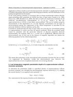
Fig. 4 Major thermal spray processes
Combustion spray burns mixtures of fuels such as acetylene and oxidizing agents (air or oxygen) that are used to
subsequently heat and accelerate particles of material injected into the hot expanding gas jets. Combustion spraying has,
during the last 15 years, been subdivided into two distinct categories: (a) Flame spray, which uses low pressure (70 to 140
kPa, or 10 to 20 psi) fuel/oxygen mixtures, burning unrestricted and external to the spray gun itself in ambient air, and (b)
HVOF spraying, which utilizes internal combustion at higher gas flow rates and pressures (up to 1.5 MPa, or several
hundred psi) generating supersonic jet exit velocities. The powder particles are also injected internally in HVOF, such that
the heat and momentum transfer to the particles, and hence particle velocity, are substantially higher (>1000 m/s) than in
conventional flame spray.
Wire arc spray utilizes two electrically conducting wires as feedstock, rather than powders. A continuous direct current
(dc) arc melts the tips of the advancing wires and a high flow (typically >1500 slm) gas jet atomizes the molten material
and accelerates the resulting small droplets toward the substrate being coated. A typical wire arc spray gun consists of a
nozzle that directs a cool, high-velocity air, nitrogen or, in special cases argon, gas jet at the wire tips and a feedback-
controlled wire-feed mechanism that continuously positions and advances the wires. Melt rate and interelectrode voltage
determine the arc gap and size distribution of the atomized droplets leaving the tips of the wires and hence affect the final
coating microstructure. Because cool gas jets are used to atomize the molten tips of feed wires in wire arc spray, the
components being coated are not heated as much as in other thermal spray processes, an advantage when thermally
sensitive substrate materials are being coated. Even thin sheets of paper can be coated by the wire arc process. Wire arc
spraying is, however, limited to electrically conductive materials (metals) as feedstock, but has the lowest processing
temperatures (at the substrate) of all the processes. Particle velocities vary, but are generally higher than in conventional
flame spray and lower than HVOF or plasma spray. Plasma spraying (see the section that follows) has the highest
particle-heating potential, but its particle velocities, although higher than conventional flame and wire arc spray, are
generally lower than those of HVOF spraying. In other cases, accelerating gas cap extensions have been added to
conventional wire arc spray systems to increase particle velocity and produce finer droplets, both leading to increased
deposit densities, and reduced differences between the microstructures and properties of wire arc sprayed deposits and
those produced by other thermal spray processes.
Plasma spray can be broken down into three major categories: (a) air plasma spray (APS), (b) "vacuum" plasma spray
(VPS) or low-pressure plasma spray (LPPS), and (c) controlled atmosphere plasma spray (CAPS), which also includes
inert gas shrouded plasma jets, depending on the environment used. These distinctions affect the level of interaction
between the process jet and materials being sprayed with the surrounding atmosphere and thus control the microstructure
and properties of the sprayed materials. All current commercially significant plasma spray processes use a nontransferred
(i.e., no arc is established to the workpiece or substrate) dc electric arc to heat gases to peak temperatures in excess of 25
× 10
3
K, producing jets of ionized "plasma" with temperature ranges of 3 × 10
3
to 15 × 10
3
K. At these temperatures, the
plasma gases (Ar, H
2
, He, or N
2
) are dissociated and ionized into an equilibrium mixture of positive ions and electrons as
energy is pumped into them by the confined arc discharge. The plasma state gives the process both its name and its ability
to melt any material exhibiting a stable melting point. A typical plasma spray device consists of a cylindrical, thoriated
tungsten cathode, which emits electrons when heated by an electric arc, located concentrically and coaxially inside a
cylindrical water-cooled copper nozzle. Electrons emitted from the cathode flow to the nozzle anode wall under the
influence of the applied electric field, typically 30 to 80 V. Gases injected into this interelectrode region are heated,
dissociated, and ionized by the electric arc and subsequently expanded to atmosphere through the nozzle as a subsonic or
supersonic plasma jet, depending on the nozzle design and pressure ratio. The gas velocity may, in some cases, exceed 1.5
× 10
3
m/s, depending on the power input, nozzle design, gas composition and flow rate. Powders are injected into the
plasma jet as fluidized streams of "carrier" gas and powder, either externally, by means of a tube that directs the stream of
powder particles radially into the hot gas jet immediately after it exits the nozzle, or internally through powder feed ports
through the nozzle wall itself. Internal injection produces longer particle heating or "dwell" times and improves melting
efficiency, enabling higher melting temperature materials to be sprayed.
Plasma spray devices generally use argon or mixtures of argon plus helium, hydrogen (H
2
), or sometimes nitrogen (N
2
) to
generate the hot plasma jets used for spraying. Coatings sprayed at low pressures (VPS), in inert atmospheres in an
enclosed pressure vessel, or using an inert gas shroud, have very low oxide inclusions and porosity levels. This is
achieved by eliminating interaction between the molten particles and oxygen being entrained into the jets from the
surrounding air. The sprayed coatings generally exhibit low oxide content, such that in many cases VPS materials have
the same, or better, properties than cast materials. This characteristic has enabled VPS processes to be used to spray form
net shapes of "difficult-to-process" materials, including ceramics, refractory metals, intermetallics, and composites.
Inert gas shrouded plasma spray has the potential of achieving vacuum plasma quality coatings under air plasma spray
conditions, thereby lowering the total processing cost. Several effective inert gas shroud designs have been developed and
reported, including porous metal nozzle inserts (Ref 11) and discrete, multijet, parallel flow designs located downstream
of the nozzle exit on a conventional plasma spray gun (Ref 12 ).
As stated above, the structures and properties of sprayed materials can vary widely, depending on the process used,
classes, and the processing conditions. The different processes each result in different thermal and velocity histories for
the injected particles. Particle melting and deformation are thus different in each thermal spray class, leading to the
differences observed in the performance of spray deposited materials. Key features of the different processes are as
follows:
• Conventional flame spray has the lowest heating potentia
l and lowest mean particle velocity of all
thermal spray processes, but is nevertheless used in many applications.
• High-
velocity oxygen fuel processes typically have the highest particle velocity, but its gas jet
temperatures limit the maximum attainable particle temperatures.
• Wire arc spray has lower processing temperatures and produces intermediate particle velocities, but
owing to its low gas temperatures can be used to coat thermally sensitive substrates.
• Plasma spray, with the highest processing t
emperatures, is most flexible with respect to materials
selection, and because of its ability to operate under inert gas conditions, is commonly chosen for
consolidating oxidation-sensitive and reactive materials.
Thermal spray has been defined as a particulate/droplet consolidation mechanism capable of processing virtually any
material and most materials combinations. Despite the widespread use of thermal spray to produce coatings, and, to a
lesser extent for spray forming, thermal spray has not been widely used for the synthesis and production of advanced
materials. Developments in thermal spray over the last 25 years, including controlled atmosphere plasma spraying,
HVOF, reactive plasma spraying, improved wire arc spray methods, new material and powder production methods, and
particularly improved process controls have, however, resulted in many new opportunities for the technology in the area
of powder consolidation.
The range of materials that can be sprayed, their possible structures, and the application of thermal spray processing are
limited only by the imagination of the users and the economic viability of the application. Thermal spray can process
many materials, in many forms, to produce deposits on many substrate materials, thus making thermal spray an ideal
technique for processing many advanced materials and structures. Many challenges, however, still remain:
• Cost/economics
• Compositional and structural control
• Deposition rate
• Control of deposit properties
Thermal spray is now, owing to recent advances in materials, powder production techniques, process understanding, and
control, at the leading edge of novel powder consolidation methods. Some recent advances are reviewed below that
present the current state of the technology for implementation as a viable powder consolidation process.
References cited in this section
10.
R.W. Smith, Equipment and Theory, Lesson from Thermal Spray Technology, Course 51,
Materials
Engineering Institute, ASM International, 1992
11.
H.C. Chen, Z. Duan, J.V.R.
Heberlein, and E. Pfender, Influence of Shroud Gas Flow and Swirl Magnitude
on Arc Jet Stability and Coating Quality in Plasma Spray, Proc. Ninth National Thermal Spray Conf.
(Cincinnati, OH), ASM International, Oct 1996, p 553-561
12.
M. Mohanty, R.W. S
mith, R. Knight, W.L.T. Chen, and J.V.R. Heberlein, Shrouded Air Plasma Processing
of Lightweight Coatings, Proc. Ninth National Thermal Spray Conf.
(Cincinnati, OH), ASM International,
Oct 1996, p 967
Thermal Spray Forming of Materials
Richard Knight and Ronald W. Smith, Center for the Plasma Processing of Materials (CPPM), Drexel University, Philadelphia, PA
Materials for Thermal Spray
Thermal spray is capable of processing materials with jet temperatures ranging from 500 to 15 × 10
3
K, which enables
virtually any material, or combination of materials, to be processed. Because only small volume powder particles are
heated in a given time and because, on solidification, only small volumes, typically 5 to 100 m in diameter, are being
cooled, segregation is not a limiting factor. On the other hand, residual stress can have detrimental effects on the
properties and performance of sprayed coatings, its significance varying from process to process and material to material.
Also, because materials are deposited in relatively thin (12 to 50 m, or 0.0005 to 0.002 in.) layers, many unique
combinations of materials can be produced.
Three characteristic types of deposit can be sprayed: (a) Monolithic materials, such as metals, alloys, intermetallics,
ceramics, and polymers; (b) composite particles such as cermets (WC/Co, Cr
3
C
2
/NiCr, NiCrAlY/Al
2
O
3
, etc.), reinforced
metals, and reinforced polymers; and (c) layered or graded materials. Some examples of these, and their particular
advantages and associated technical challenges, are described below.
Monolithic Materials
Metals. Tungsten, molybdenum, rhenium, niobium, superalloys (nickel, iron, and cobalt base), zinc, aluminum, bronze,
cast iron, mild and stainless steels, NiCr and NiCrAl alloys, cobalt-base Stellites, cobalt/nickel-base Tribaloys, and
NiCrBSi "selffluxing" Colmonoy have all been successfully thermal spray consolidated either as coatings or structural
deposits. Recently Tribolite (FeCrNiBSi) and AmaCor (amorphous) alloys have also been developed for spraying and
exhibit excellent wear and corrosion resistance (Ref 13). Monolithic alloys have advantages due to their similarity to
many base metals requiring repair, their high strength, and their corrosion, wear and/or oxidation resistance. Applications
include automotive/diesel engine cylinder coatings; piston rings or valve stems; turbine engine blades, vanes, and
combustors; protection of bridges and other corrosion-prone in frastructure; petrochemical pumps and valves; and mining
and agricultural equipment. Except in the case of controlled-atmosphere spraying (VPS, inert chamber, and shrouded jets)
thermally spraying these metals and alloys produces microreinforced composites of monolithic alloys due to their varying
levels of oxide inclusions. Figure 2 shows a range of microstructures for thermally sprayed monolithic metals. These
coatings exhibit characteristic lamellar microstructures with the long axis of impacted splats oriented parallel to the
substrate surface, together with a distribution of similarly oriented oxides. Oxide content varies from relatively thick
layers to finely distributed, particulate, intersplat phases, depending on whether the coatings are wire arc, plasma, or
HVOF sprayed. The progressive increases in particle velocity of these processes leads to differing levels of oxide, and
differing degrees of oxide breakup on impact at the surface. Oxides may increase coating hardness and may also provide
lubricity. Conversely, excessive and continuous oxide networks can lead to cohesive failure of a coating and contribute to
excessive wear debris. It is thus important, when selecting materials, coating processes, and processing parameters, that
oxide content and structure be controlled to acceptable levels.
Thermal spray coatings may, depending on the spray process, particle velocity and size/size distribution, and spray
distance, also contain varying levels of porosity and unmelted particles. High levels of porosity may lead to early deposit
failure owing to poor intersplat cohesion. Conversely, low levels of porosity (<5%) may be beneficial in tribological
applications through retention of lubricating oil films. Lamellar oxide layers can also lead to lower wear and friction due
to the lubricity of the oxide. The porosity of thermal spray coatings is typically <5% by volume. The retention of some
unmelted and/or resolidified particles can lead to lower deposit cohesive strength, especially in the case of "as-sprayed"
materials with no postdeposition heat treatment or fusion.
Other key features of thermally sprayed deposits are their generally very fine grain structures and microcolumnar
orientation. Thermally sprayed metals, for example, have reported grain sizes of <1 m prior to postdeposition heat
treatment. Grain structure across an individual splat thus normally ranges from 10 to 50 m, with typical grain diameters
of 0.25 to 0.5 m, due to the high cooling rates achieved ( 10
6
K/s) (Ref 1). Such rapid cooling rates, known to form
fine-grained martensitic microstructures in steels, contribute to the high strengths exhibited by thermally sprayed
materials. The "as-sprayed" microstructure of a typical metallic coating is shown schematically in Fig. 5.
Fig. 5 Schematic microstructure of an "as sprayed" thermally sprayed metal deposit
The tensile strengths of "as-sprayed" deposits can range from 10 to 60% of those of the fully cast or wrought material,
depending on the spray process used. Spray conditions leading to higher oxide levels and lower deposit densities result in
the lowest strengths. Controlled-atmosphere spraying leads to 60% strength, but requires postdeposition heat treatment
to achieve near 100% values. Low "as-sprayed" strengths are related to limited intersplat diffusion and limited grain
recrystallization during the rapid solidification characteristic of thermal spray processes. The microstructures of thermally
sprayed metals are typically very uniform and exhibit excellent tensile properties. After heat treatment at >0.8 T
m
(melt
temperature), much of the characteristic lamellar structure recrystallizes, but depending on the alloy, grain growth may be
limited to <100 m. The fine-grained structures, found in highly alloyed, grain-growth-stabilized superalloys, have been
found to improve thermal fatigue properties, but to increase creep rates. After postdeposition heat treatment (vacuum or
hot isostatic pressing), the high-temperature creep properties of these alloys have been found to be lower than cast alloys
due to the fine grain sizes and the oxygen interstitials. In this reported work, final grain size in heat-treated
microstructures was found to be substantially retained, due to very stable oxide and/or carbide networks formed during
solidification after spraying, many times originating from the alloy feedstock powders. Final deposit ductilities were also
lowered by the retention of relatively high oxygen contents originating from the surfaces of the original powders (Ref 14).
On the beneficial side, the addition of nitrogen to steel matrices by promoting, rather than minimizing, atmospheric
interactions during air plasma spraying has been shown to increase the strength of thermally sprayed steels and is a viable
strengthening mechanism for selected monolithic alloys (Ref 15). Grain nucleation is suppressed in alloys containing high
levels of silicon and boron, yielding so-called "amorphous" coatings (Ref 16). These "micrograined" or amorphous
microstructures contribute to the high strengths and toughnesses of thermally sprayed metals at low to intermediate
temperatures. Fatigue failure is also harder to propagate in such structures, except through coating defects such as oxide
inclusions. The role of grain size effects on the wear performance of thermally sprayed coatings is understood, but has not
been independently measured; hence it is hard, for example, to determine its contribution to sliding-wear performance.
Ceramics. Oxides such as Al
2
O
3
, ZrO
2
(stabilized with MgO, CeO, Y
2
O
3
, etc.),TiO
2
, Cr
2
O
3
, and MgO; carbides such as
Cr
3
C
2
, TiC, Mo
2
C and SiC (generally in a supporting metal matrix) and diamond; nitrides such as TiN and Si
3
N
4
, and
spinels or perovskites such as mullite and superconducting oxides, have all been thermally spray deposited. Sprayed
deposits of these materials are used to provide wear resistance (Al
2
O
3
, Cr
2
O
3
, TiO
2
, Cr
3
C
2
, TiC, Mo
2
C, TiN, and
diamond), thermal protection (Al
2
O
3
, ZrO
2
, MgO), electrical insulation (Al
2
O
3
, TiO
2
, MgO), and corrosion resistance.
With the exception of SiC (which sublimes), diamond, and SiC or Si
3
N
4
(which must be in a metallic binder), ceramics
are particularly suited to thermal spraying, with plasma spraying being most suitable due to its high jet temperatures.
The processing and materials flexibility and high temperatures gives plasma spraying a leading role in the spraying of
thermal barrier coatings (TBCs), although the use of HVOF is also being investigated. Thermal barrier coatings are, after
wear and corrosion coatings, likely to be one of the largest growth markets for thermal spray, with increased use in the
automotive, metalworking, and chemical industries. Such broad usage, however, will require a more thorough
understanding of the behavior of these materials during high-temperature service. Thermal spray processing of ceramic
materials that melt, rather than decompose, is essentially the same as for metals; however, the higher mean melting
temperatures and low thermal conductivity of ceramics limits the selections of thermal spray processes that can
successfully melt these materials. Combustion spray methods generally have insufficient process jet enthalpies and/or
particle dwell times to efficiently spray ceramic powders. Most HVOF systems are also limited in their efficient spraying
of ceramics, where the powder sizes required are either too small or deposit efficiencies are too low for the processes to
be economically viable. Wire arc spray is excluded because it needs conductive materials, leaving only plasma spraying
as an economic method for spraying ceramic powders. There are, however, some specialized flame spray techniques such
as the "Rokide" process (Norton Company), which uses a combustion jet to melt the tips off pressed-and-sintered ceramic
rods and a secondary gas jet that atomizes the molten material from the melting rod tip. Air plasma spraying is, however,
most widely used to deposit ceramics, finding applications in TBCs, wear coatings on printing rolls (Cr
2
O
3
), and for
electrical insulators (Al
2
O
3
).
The microstructures of sprayed ceramics are similar to those of metals, with two important exceptions: grain orientation
and microcracking. Rapid solidification of small droplets (generally <50 m) results in very fine grains as in metals;
however, owing to the low thermal conductivity of ceramics, multiple grains may exist though a splat thickness, whereas
in metals a single grain may cross an entire splat and even grow into an adjacent one. Intersplat and intrasplat
microcracking is widespread in ceramic coatings, resulting from the accumulation of highly localized, residual cooling
stresses. Figure 6 illustrates the typical microstructure of a thermally sprayed yttria-stabilized zirconia ceramic coating,
showing fine grains, characteristic lamellar structure, and a network of porosity and microcracks.
Fig. 6 Typical microstructure of a thermally (plasma) sprayed ceramic (yttria-stabilized zirconia)
Splats normally exhibit through-thickness cracking owing to the very low ductility of most ceramics, but these cracks do
not usually link up through the whole deposit thickness, at least not until an external stress is applied. Microcracking of
splats is a major contributor to the effectiveness of TBCs, even under high-temperature gradients and moderate strains,
conditions under which conventionally formed bulk ceramics would fail.
Intermetallics. Usually produced from powders due to their intrinsically low ductility, intermetallics are generally
consolidated either by pressing and sintering or hot isostatic pressing. Over the last 15 years researchers have reported on
the thermal spray consolidation and forming of intermetallic powders. The high heating and cooling rates of the thermal
spray process reduce the segregation and residual stresses that ordinarily limit the formability of these brittle materials.
Thermal spray processes are also able to deposit materials onto mandrels, building up thin layers of material and thus
forming near-net shapes and providing the opportunity for "engineered microstructures" and functionally graded
structures. Researchers have also reported on the plasma spraying of TiAl, Ti
3
Al, Ni
3
Al, NiAl, and MoSi
2
with excellent
deposit characteristics and properties. Improved ductilities have been obtained, with tensile strengths equal to, or better
than, those of materials consolidated by other powder processing techniques.
Thermal spray processing of intermetallics, unlike ceramics, is generally not an application for plasma spraying. Plasma
spray in controlled atmospheres is, however, the method of choice for the production of bulk deposits. High-velocity
oxygen fuel and other combustion spray techniques are normally only used to spray compatible intermetallics, such as
semiconducting, insulating, or corrosion- and wear-resistant coatings. Most intermetallics are very reactive at high
temperatures and very sensitive to oxidation, hence the preference for using inert atmosphere plasma spray. Plasma spray
forming is also well suited for the net-shape forming of brittle intermetallics. Investigators have found that plasma spray
forming can actually increase the ductility of intermetallics such as MoSi
2
(Ref 17) and NiAl/Ni
3
Al (Ref 18). These
improvements were linked to a decrease in grain boundary and/or splat interface contaminants that limit localized plastic
flow under an applied strain and lead to early crack linking, thus lowering the overall plastic flow, measured as ductility.
It has been shown, for example, that reactive plasma species reacting at the surfaces of MoSi
2
powder particles in flight
actually reduce the residual SiO
2
content below that of commercial MoSi
2
powders and hence reduce the SiO
2
"pest"
reaction that degrades the properties of pressed-and-sintered or hot isostatically pressed MoSi
2
.
The as-sprayed microstructures of thermally sprayed intermetallics are very similar to those of metals. Figure 7 shows the
microstructure of thermal spray consolidated MoSi
2
, showing the characteristic lamellar structure and fine grains.
Intermetallics are generally somewhat more porous than sprayed metals owing to their limited ductility and low plasticity,
which translates into a narrower "processing window" of plasma spray parameters for the production of high-density
intermetallics, requiring tighter process control than for spraying metals. Higher-velocity plasma spray processes are
preferred because the increased particle velocities result in more complete deformation of individual splats and denser
deposits overall.
Fig. 7 Microstructure of a plasma spray consolidated intermetallic material (MoSi
2
)
Polymers. Polymeric materials can also be successfully thermally sprayed, provided they are available in particulate
form. Thermal spraying of polymers has been commercially practiced for 20 years, and a growing number of
thermoplastic polymers and copolymers have now been sprayed, including urethanes, ethylene vinyl alcohols (EVAs),
nylon 11, polytetrafluoroethylene (PTFE), polyetheretherketone (PEEK), polymethylmethacrylate (PMMA), polyimide,
and copolymers such as polyimide/polyamide, Surlyn, and Nucryl (Du Pont), and polyvinylidene fluoride (PVDF).
Conventional flame spray and HVOF are the most widely used thermal spray consolidation methods used to date (Ref
19), although use of plasma spray has also been reported. Figure 8 shows a typical dense, well-bonded, HVOF-sprayed
nylon coating. Consolidation of polymers to full densities and high cohesive strengths, unlike metals, relies to some
extent on continued heat input to the polymer layers after deposition onto the substrate. This may be due to the more
complex, long-range-ordered nature of the molecular bonding in polymers, compared to the simpler, short-range-order
bonding in metals. Thermal spray, a high-temperature, rapid-heating/rapid-solidification process, has been found to
decompose polymeric materials, lowering the molecular weight and producing "charring." In many cases, however, this
does not impair the functionality of the sprayed coating, although it does change certain polymer properties compared to
polymers consolidated by conventional means. Despite thermal spraying of polymers having been practiced for more than
20 years, little research into the material structures and properties has been carried out until recently. Commercial interest
in this application is growing, for applications such as aqueous corrosion protection and as a solventless processing
alternative to environmentally hazardous volatile organic compound (VOC)-based techniques.
Fig. 8 Microstructure of an HVOF-sprayed nylon coating
Composite Materials
Thermal spraying, either as a coating or as a bulk structural consolidation process, has clearly demonstrated advantages
for the production of composites. Difficult-to-process composites can be readily produced by thermal spray forming, with
vacuum plasma spray being the process of choice for the most reactive matrix materials. Particulate-, fiber-, and whisker-
reinforced composites have all been produced and used in various applications. Particulate-reinforced wear-resistant
coatings such as WC/Co, Cr
3
C
2
/NiCr, and TiC/NiCr are the most common applications and comprise one of the largest
single thermal spray application areas. Figure 9 shows schematically the diverse forms of composites that can be
thermally spray formed.
Fig. 9 Schematic microstructures of possible thermally spray-
formed composites. (a) Deposit with a
particulate-reinforced second phase. (b) Deposit with a whisker-reinforced second phase.
(c) Deposit with a
continuous-fiber-reinforced second phase
Whiskers of particles can be incorporated using so-called "engineered" powders, mechanical blending, and by coinjecting
different materials into a single spray jet. Mechanical blends and coinjection, although useful, have been found to result in
segregation of the reinforcing phase and, in many cases, degradation of the second-phase whiskers or particles. Thermal
spray composite materials can have reinforcing-phase contents ranging from 10 to 90% by volume, where the metal
matrix acts as a binder, supporting the reinforcing phase. The ability to consolidate such fine-grained, high reinforcing
phase content materials is a major advantage of thermal spray over other methods used to produce composites.
Thermal spraying of composite materials with discontinuous reinforcements, such as particulates or short fibers, is usually
accomplished by spraying powders or powder blends. Investigators have developed techniques for the production of
continuous fiber-reinforced materials that overcome the "line-of-sight" limitations of thermal spray processes. This
includes "monotape" fabrication techniques, where continuous fibers are prewrapped around a mandrel and a thin layer of
a metal, ceramic, or intermetallic matrix material is sprayed (Ref 20). Plasma, HVOF, and wire arc spray have been used,
although in the cases of intermetallics and high-temperature alloys, controlled atmosphere plasma spray (VPS) has
generally been used. The fibers are thus encapsulated within thin monolayer tapes and are subsequently removed for
consolidation to full density by hot pressing with preferred fiber orientations, producing continuously reinforced bulk
composites.
Powders for Sprayed Composites
Discontinuously reinforced composites produced using thermal spray techniques use either composite powders or direct
reactive synthesis approaches, as described below. Powders can be produced mechanically, chemically,
thermomechanically, or by using high-temperature synthesis. "Engineered powders" defines powders in which different
phases are incorporated to produce a "microcomposition" of the final desired structure. Typically these powders contain
the desired sizes, size distributions, and morphologies of the equilibrium phases. These powders also permit the
introduction of higher concentrations of phases than those normally achievable through conventional melt or reaction
processing. Figure 10 shows two types of powder that could be produced in this way: short ceramic fibers within a metal
matrix and an intermetallic-matrix material reinforced with more ductile phases. The latter has been found to be a viable
approach for increasing the fracture toughness (K
Ic
) of intermetallics. Varying reinforcing phase combinations,
compositions, morphologies, and distributions can be produced. The rapid heating and cooling experienced by these
powders during thermal spray forming limits dissolution and degradation of the phases, which remain relatively
unchanged after consolidation, although some microstructural refinement and solutioning can take place. Generally, more
significant changes occur during conventional powder consolidation processes because of the longer processing times.
Fig. 10 Schematic representations of typical "composite" thermal spray powders
Mechanical Blends. Blended powders are produced by mixing the required proportions of a binder phase (a metal, an
intermetallic, or a ceramic) together with a reinforcing phase. The matrix and reinforcing phases may segregate over time
during shipping, handling, and feeding into a thermal spray process and often yield poor "as-sprayed" deposit uniformity.
Many mechanical blends can, however, be "agglomerated" and fixed using an organic binder, which reduces their
sensitivity to handling. Spherical agglomerates are known to flow and feed better, and spray drying has been used to
produce such materials. Agglomerated powders have enabled thermally sprayed deposits with improved uniformity to be
produced, although the high viscosity, shear, and thermal forces acting on injected agglomerated particles tend to break
the agglomerates, leading to segregation and direct exposure of the second phase to the thermal spray jet. Physically and
thermally stable agglomerates are thus desirable.
Agglomeration, Sintering, and Melt Densification. The mechanical stability of agglomerated composite particles
can be improved by agglomeration and sintering, which is a solid or rapid "matrix" melting and cooling process. Metal-
matrix/ceramic hard-phase-reinforced powders (e.g., WC/Co, Cr
3
C
2
/NiCr, NiCrAlY/Al
2
O
3
, etc.) can be sintered in the
solid state by heating in a protective atmosphere furnace, sometimes using a fluidized bed, followed by a gentle milling to
break any weak interagglomerate bonds. Agglomerated and sintered powders retain a level of porosity, typically 5 to 10%
by volume, depending on the reinforcing phase/matrix combination, the sintering time, and temperature. Retained
porosity, although not generally a source of phase segregation in thermally sprayed deposits, can lead to higher as-sprayed
porosity and increases the spray jet melting enthalpies required to melt the powders because the thermal conductivity of
the individual particles is lowered by the porosity. Melting of metallic binding phases and retention of spherical particle
morphologies can be achieved by processing the powders through a thermal plasma jet. Known as "plasma densification,"
this process produces spherical powders exhibiting near 100% particle density and uniform distributions of reinforcing
phases. Plasma-densified powders result in the most uniform thermal spray-consolidated deposits, but at significantly
increased cost owing to the additional handling, processing steps, and lower process yields.
Self-propagating high-temperature synthesis (SHS) is a composite powder production method now finding
increasing application in thermal spray forming. The SHS process exploits the high heats of formation released from
exothermic reactants which, when mixed and ignited, produce a self-sustaining combustion-type reaction that propagates
until all reactants are consumed. Self-propagating high-temperature synthesis processing uses mixtures of reactant
powders placed in a reactor vessel, generally in an argon atmosphere. The reactant mixture is then ignited using an
incandescent filament or laser beam. Self-propagating high-temperature synthesis has been developed to the point where
it is now capable of producing composite materials with well-controlled distributions of carbides or other reacted phases
in metallic or intermetallic matrices (Ref 21, 22). Self-propagating high-temperature synthesis produces low-density,
porous "ingots" that must then be further processed by crushing, milling, and screening to yield powders in size
distributions compatible with thermal spraying. Researchers have successfully thermally sprayed SHS-produced MoSi
2
,
SiC-reinforced MoSi
2
, FeCr/TiC, and NiCr/TiC materials. The sprayed deposits reportedly yielded equivalent, and in
many cases superior, properties to deposits produced from powders produced by other synthesis routes. Some examples
of the improved properties obtained include increased wear resistance in TiC/metal-matrix composites and increased
fracture toughness in intermetallic composites such as MoSi
2
/SiC (Ref 23). Figure 11 illustrates the SHS powder
production route, including powder synthesis and consolidation via plasma spray forming.
Fig. 11 SHS powder synthesis and plasma spray consolidation process
References cited in this section
13.
R.W. Smith, P. Kangutkar, R. Drossman, and R. Krepski, A New Iron Base Thermal Spray Coating for
Wear Resistance, Proc. 13th International Thermal Spray Conf.
(Orlando, FL), ASM International, 1992, p
653-659
14.
K. Tanaka et al., J. Mater. Sci., Vol 22, 1987, p 2192-2198
15.
K. Ishizaki et al., J. Mater. Sci., Vol 24, 1989, p 3553-3559
16.
S. Matsumoto, T. Kobyashi, and M. Hino, Proc. Eighth International Symposium on Plasma Chemistry,
Vol 4, IUPAC, 1987, p 2458
17.
R.G. Castro et al.,
Ductile Phase Toughening of Molybdenum Disilicide by Low Pressure Plasma Spraying,
Mater. Sci. Eng., Vol A155, 1992, p 101-107
18.
S. Sampath, H. Herman, and S. Rangaswamy, Ni-Al Re-evaluated,
Proc. First National Thermal Spraying
Conf. (Orlando, FL), ASM International, 1987, p 47-53
19.
L.S. Schadler, K.O. Laul, R.W. Smith, and E. Petrovicova, Microstructure and Mechanical Properties of
Thermally Sprayed Silica/Nylon Nanocomposites, J. Thermal Spray Technol., Vol 6 (No. 4), 1997, p 475-
485
20.
L.J. Westfall, Composite Monolayer Fabrication by an Arc-Spray Process,
Proc. First National Thermal
Spray Conf. (Orlando, FL), ASM International, 1987, p 417-426
21.
Z.A. Munir and V. Anselmi-Tamburini, Self-Propagating Exotherm Reactions: The Synthesis of High-
Temperature Materials by Combustion, Mater. Sci. Rep., Vol 3 (No. 7/8), 1989, p 277
22.
S. Sampath et al., Synthesis of Intermetallic Composite Powders via Self-Propagating Synthesis,
Proc. 1993
Powder Metallurgy World Congress (Kyoto, Japan), Japan Societ
y Powder and Powder Metallurgy, 1993, p
401-403
23.
R.G. Castro, H. Kung, and P.W. Stanek, Reactive Plasma Spraying of MoSi
2
using an Ar-10% CH
4
Powder
Carrier Gas, Mater. Sci. Eng., Vol A185, 1994, p 65-70
Thermal Spray Forming of Materials
Richard Knight and Ronald W. Smith, Center for the Plasma Processing of Materials (CPPM), Drexel University, Philadelphia, PA
Thermal Spray Forming
While the thermal spray technology described above originated primarily as a coating or surfacing process, with materials
being deposited as thin (<250 m), nonload-bearing coatings for dimensional restoration, wear, corrosion, and thermal
protection, it has also evolved, during the last 50 years, into a process capable of spray forming free-standing materials
onto mandrels at thicknesses of >100 mm. Early applications included zirconia -oxygen sensors and bulk ceramic
materials for crucibles. Historically "difficult-to-form" materials such as the refractory metals tungsten, hafnium,
molybdenum, and tantalum; superalloys; and intermetallics have now all been deposited with varying degrees of success,
with the ultimate mechanical properties of the sprayed deposit being the main limitation. Process technology advances,
such as HVOF, which can produce sprayed deposits with lower tensile stresses and degrees of thermal degradation than
other processes and with increased deposit density, controlled-atmosphere plasma spray, and improved powder
formulations and morphologies have all contributed to the successful development of thermal spray forming of monolithic
and composite materials.
Thermally sprayed coating deposits are usually <1000 m thick, more typically 400 m. Thermal spray forming,
however, can yield deposit thicknesses in excess of 25 mm. Free-standing shapes can be produced by spraying onto
sacrificial mandrels, which are mechanically or chemically removed after spraying.
The incremental nature of thermal spray processes, using particulate-based feedstocks, and with deposited layers typically
15 to 25 m thick, enables graded and laminated structural materials to be formed. Also, because of the high processing
temperatures and high localized forming energies (high particle kinetic energies at impact), traditionally difficult-to-form
materials can be processed into near-net-shape components. Virtually all common and refractory metals, many
intermetallics, ceramics, and combinations of these have been spray formed as "composite" materials. The properties
(apart from the ductility of metals) of these deposited materials, after postdeposition heat treatment, have been reported to
be close to, if not exceeding, those of cast or wrought materials. The ductility of metals is limited by contamination
sources occurring either within the feedstock powders used, or in the spray process itself, due to oxidation of the material
during heating under atmospheric conditions. Nickel-base superalloys and other heat-resistant alloys have all been
thermally spray formed during the last 20 years, either as preforms or as a component repair technique. Plasma spray in
low pressure inert/controlled atmosphere (VPS) chambers has been found to be most suitable for forming these alloys;
however, recent investigations using HVOF have shown that this too may be a viable alternative to plasma spraying in
controlled atmospheres, at least for some component repair applications. Despite the technical capability of thermal spray,
however, economics and process/coating reliability concerns related to material structure, uniformity, and material
properties still limit the use of thermal spray forming.
The current major advantages of thermal spray forming techniques are in the forming of refractory metals, both in graded
or layered structures and in composites. Some of the more innovative spray forming application developments are
described below, together with some insights into emerging technologies that may ultimately lead to expanded
implementation of thermal spray forming as a materials processing technique.
Reactive Plasma Spray Forming
Research in recent years has demonstrated that the synthesis of advanced materials by chemical routes is more promising
than many "conventional" processing methods casting, forming, and possibly powder metallurgy (Ref 24). Plasma spray
forming, a rapid particulate consolidation, high-temperature process, has an inherent suitability for chemical synthesis and
is thus a strong candidate for synthesizing multiphase, advanced materials. As described in the literature (Ref 25), plasma
spray coating and forming have been practiced for many years and are now practical and economical methods for
processing difficult-to-form intermetallic, ceramic, and composite materials (Ref 1, 2, 26). The development of plasma
spraying in controlled atmosphere chambers (VPS or LPPS) in the early 1970s (Ref 27, 28, 29) was a key factor behind
its advancement from a coating to a forming technology. Controlled-atmosphere plasma spraying, adapted for reactive
plasma spraying, has recently been developed to combine controlled dissociation and reactions in thermal plasma jets, for
the in situ forming of new materials or to produce new phases in sprayed deposits. Reactive plasma spray forming is
consequently emerging as a viable method for producing a wide range of advanced materials. The process, a logical
evolution from conventional plasma spraying, allows "reactive" precursors to be injected into the particulate and/or hot
gas streams. These reactive precursors may be liquids, gases, or mixtures of solid reactants which, on contact with the
high-temperature plasma jet, decompose or dissociate to form highly reactive and ionic species that can then react with
other heated materials within the plasma jet to form new compounds. Figure 12 illustrates the reactive plasma spray
concept. Chemical reactions rely on plasma-induced dissociation of the injected precursors, for example gaseous methane
(CH
4
), which decomposes into elemental or ionic species such as , C
4-
or even atomic carbon. These species can
react with other elements to produce carbides such as TiC and WC, or under certain conditions, diamond or diamondlike
carbon (DLC) films. Figure 12 shows the plasma heating of gases, using either a nontransferred electric arc or an
inductively coupled plasma (ICP) radio frequency (RF) discharge; injection of reactive precursors into the plasma jet; and
injection of powders in a carrier gas stream. Injection locations may vary depending on the materials or reactions desired
and can be directly in the plasma generator (torch or gun) or into a reactor located immediately downstream. The primary
requirements are that the precursors dissociate into reactive "species" and that the reaction times and temperatures are
sufficiently long for the desired products or phases to form. Reactive plasma spray forming has several key components,
as shown in Fig. 12:
• A thermal plasma generator
• A method of injecting the reactants or precursors
•
A reaction region where compounds can form and nucleate, either on the surfaces of particles or on a
substrate
• A gas jet to transport the heated reactants and products to the surface(s) on which the products are
formed
Fig. 12 Reactive plasma spray process for the synthesis of composite materials
Reactive plasma spray applications include the synthesis of composite materials, shaped brittle intermetallic alloys,
reinforced or toughened ceramics, and tribological coatings with in situ formed hard or lubricating phases. Reactive
plasma spray forming enables a wide range of materials to be produced, for example, aluminum with AlN, Al
2
O
3
, or SiC;
NiCrTi alloys with TiC or TiN; intermetallics such as TiAl, Ti
3
Al, MoSi
2
, and other ceramics with oxides, nitrides,
borides, and/or carbides. All of these have been produced in situ in reactive thermal plasma jets.
Figure 13 shows typical microstructures of some reactively plasma sprayed materials, demonstrating the versatility of the
process for the in situ forming of metal/carbide, metal/nitride, and ceramic composites.
Fig. 13 Microstructures of reactively plasma sprayed (a) Al
2
O
3
/SiAlON and (b) MoSi
2
/SiC
Research indicates, however, that significant technical challenges still remain because, despite the promises and
advantages indicated previously, the yields and quality of the final products depend strongly on the starting precursors,
their injection methods, and the atmospheres in which they are sprayed (Ref 24, 30). Monolithic SiC, SiN, and AlN
powders have also been synthesized in plasma jets (Ref 31, 32). The uniformity of these particular materials has
considerable variability, however, and has limited the practical use of many plasma spray processes for forming
monolithic compounds, although commercial plasma production of ZrO
2
and TiO
2
powders in plasma jets has been
reported (Ref 9).
Recent investigations have demonstrated that reactive plasma spray forming utilizing incomplete or nonequilibrium
reactions in plasma jets to form mixtures of phases can produce functional composites with the reactant products
embedded in metallic, ceramic, and even intermetallic matrices. These materials have been shown to be very hard and
have potential application as wear-resistant coatings (Ref 33). These reactively plasma sprayed coatings were, in practice,
metal-matrix composites with in situ reacted hard phases formed when the reactive gas mixtures reacted with molten
metal particles. Fine TiC, WC, TaC, and other refractory carbides, oxides, silicides, or nitrides have been spray formed in
situ as particulate phases in near-net-shape metallic, intermetallic, and ceramic matrices, thus eliminating many difficult
post-forming operations. Lightweight structural materials such as Ti
3
Al, TiAl, NiAl, and MoSi
2
have also been produced
by reactive spray forming. In these cases, aluminum metal powders were injected into TiCl
4
plasmas to produce TiAl.
Molybdenum particles have also been injected into plasma jets seeded with disilane (Si
2
H
6
) to form MoSi
2
.
The utility and potential of reactive plasma spray synthesis is further illustrated by two high potential examples presented
below. Research and development in these areas is receiving increased attention as the potential of thermal plasma
processing of these high value materials is realized.
Spray Forming of Superconducting Oxides (High T
c
Ceramics)
Researchers have reported on the deposition and synthesis of high critical temperature (T
c
) ceramic superconductors using
dc and RF induction coupled plasma jets (Ref 34, 35). Dense, thick deposits have been produced using prealloyed 1-2-3
YBaCu
x
O
y
powders, although the high T
c
phase was only formed after a postdeposition heat treatment in oxygen.
Researchers have not yet been able to directly plasma spray form the superconducting phase by dc plasma spraying
prealloyed powders because the rapid cooling of the "1-2-3" materials from the liquid state suppresses direct formation of
the high T
c
phase. The microstructures of the deposits were also found to contain many small grains and pores as well as
fine cracks that limited the maximum critical currents to very low values. Researchers at the University of Minnesota
have developed a method of overcoming this limitation by using a vapor phase, plasma-assisted, reactive plasma spray
process (Ref 34). This system uses an RF, induction-coupled, plasma heater in combination with liquid feeding of oxalate
precursors of the copper, yttrium, and barium components. The liquids were ultrasonically atomized to generate an
aerosol, subsequently carried by an oxygen carrier gas into the RF plasma jet. The longer heating, dissociation, and
reaction times available in RF plasma jets have been shown to be able to produce the high-temperature 1-2-3 T
c
phase
directly. Thin, epitaxially deposited, films of the "1-2-3" high-T
c
superconducting oxides were formed without the need
for any postdeposition heat treatments or annealing in oxygen. The films were single crystals that exhibited none of the
critical current limitations characteristic of the directly plasma sprayed materials.
Diamond Synthesis and Deposition
Several researchers have synthesized diamonds using either dc or RF thermal plasma jets (Ref 35, 36, 37) and have shown
that generation of radicals and ionic hydrogen, which typically occurs under many plasma jet conditions, leads to
the formation of diamond films. In these cases, precursor gases such as methane and hydrogen were injected into the
plasma jets, where the high temperatures (>10,000 K) produced the required ionic concentrations such that on collision
with a heated surface at 1000 °C amorphous carbon and diamond phases were formed. It is generally accepted that the
ionic hydrogen assists in preferentially etching away the amorphous carbon phase, leaving diamond as the surface film.
High growth rates (>1 m/min) can be achieved; however, the exact morphology and bonding of the deposited diamond
films varies and can be a limiting factor. A wide range of thermal plasma processing conditions with a wide range of
environments have now been used to produce diamonds. The critical elements of diamond growth clearly occur in the
thin, plasma-enhanced, reaction zone created immediately above the substrate surface when the thermal plasma jet
impinges on the substrate surface. The precise formation mechanisms are not yet completely understood, but research is
now showing that it is the thermal plasma jet conditions that are primarily responsible for producing diamonds at high
rates.
Functionally Gradient Materials
Functionally gradient materials (FGMs) are a rapidly growing application area with significant promise for the future
production of (a) improved materials and devices for use in applications subject to large thermal gradients, (b) lower-cost
clad materials for combinations of corrosion and strength or wear resistance, and (c) perhaps improved electronic material
structures for batteries, fuel cells, and thermoelectric energy conversion devices. The most immediate application for
FGMs is in thermally protective claddings, where large thermal stresses could be minimized and component lifetimes
improved by "tailoring" the coefficients of thermal expansion, thermal conductivity, and oxidation resistance. These
FGMs could, and indeed are, finding use in turbine components, rocket nozzles, chemical reactor tubes, incinerator burner
nozzles, or other critical furnace components. Figure 14 illustrates an example of a thermally sprayed FGM proposed for
the protection of copper using a layered FGM ceramic structure. Successful fabrication of this would have application as
improved burner nozzles, molds, and furnace walls (Ref 38).
Fig. 14 Schematic of a thermally sprayed FGM for burner nozzle applications
Thermally protective FGMs may also be used in applications where reduced weight is needed, for example in aircraft or
other transportation systems, or for the thermal protection of lightweight polymeric materials using insulating materials.
The economic production of graded metallic, oxide, and intermetallic structures may also enable advanced batteries, solid
oxide fuel cells (SOFCs) (Ref 39), and thermoelectric devices consisting of alternating layers of semiconducting materials
(FeSi
2
) to be produced.
Thermally sprayed graded materials are now also being considered for the production of oxide/metal/air-type
electrode/electrolyte systems. This has been proven by research and development on SOFCs and electrode developments
(Ref 40) using thermal spray methods. Spray-formed battery cells promise to be both lightweight and significantly more
environmentally acceptable than current lead/acid and nickel/cadmium batteries, thus opening up large potential markets
in consumer, computer, and automotive electronics. These products would all use FGMs, which promises to increase
performance and lower the cost. Thermal spray forming of such gradient structures has been proposed because of the
unique ability this approach has of being able to deposit thin, individual layers of a wide range of materials metals,
intermetallics, and ceramics thereby enabling layered or continuously graded structures to be produced. The forming of
composite gun barrels by spraying tubular laminates and superalloy composites (Ref 41), intermetallics, and refractory
metals is one example of completed work. Thick thermally sprayed coatings with graded structures are being developed
for several commercial applications, including:
• The ceramic outer air seals in aircraft gas turbines and other "clearance-
control" coatings in rotating
machinery
• Thick, multilayer, TBCs for heavy-duty diesel engine pistons
• High-performance dielectric coatings for electronic devices
• Wear-resistant coatings for diesel engine piston rings
• Oxidation-resistant coatings for high-temperature conditions
Future growth of FGM applications will ensure that thermal, particularly plasma, spray forming will increase and
develop, provided that material properties can be controlled and processing costs can be optimized.
Thermal spray forming can produce continuous gradations of metals, ceramics, and intermetallics, either in alternating
stepwise layers or as microlaminates. Materials could be sprayed to replicate the mechanical behavior of a material, for
example making tungsten shear locally in high-impact applications. Normally under high impact, tungsten and its alloys
behave in a ductile fashion, exhibiting significant plastic deformation, or "mushrooming." When localized shear behavior
is required, however, very thin, alternating layers of intermetallic materials can be deposited concurrently while spray
forming the bulk tungsten alloy. Thermal spray forming thus enables microlaminate structures to be formed that can be
used to locally modify the overall mechanical behavior of the system. The same approach could also be used to modify
the electrical or thermal properties of a material.
Thermally sprayed gradient structures have also been proposed as strain controlled coatings and/or structures and for
electrical devices, as shown schematically in Fig. 15.
Fig. 15
Other examples of thermally sprayed FGMs. (a) Multilayer coating for strain control. (b) Sprayed
electrodes for SOFCs. (c) Sprayed alternating layers for thermoelectric devices
The powder production route for materials permits the production of oxides and/or brittle intermetallics that have unique
electrical and thermal properties. Figure 15 shows that oxide-based fuel cells can be spray formed by depositing
alternating layers of oxide and metal electrodes, and oxide electrolytes. The figure also shows the spraying of alternating
layers of thermoelectric materials (FeSi
2
) and the concurrent deposition of metallic electrodes. This processing combines
the grading capability of thermal spray together with its ability to spray materials with widely varying melting points, thus
truly realizing the advantages of thermal spray forming.
References cited in this section
1. M. Jackson, J. Rairden, J. Smith, and R.W. Smith, J. Metals, Vol 1, 1981, p 146
2. S. Sampath and H. Herman, Thermal Spray Technology, ASM International, 1988, p 1-8
9. M. Thorpe, Chem. Eng., Nov 1991, p 54-57
24.
R.W. Smith, Reactive Plasma Spray Forming for Advanced Materials Synthesis, Powder Metall. Int.,
Vol
25 (No. 1), 1993, p 9-16
25.
R.W. Smith and R. Knight, Thermal Spraying I: Powder Consolidation From Coating to Forming, JOM,
Vol 47 (No. 8), 1995, p 32-39
26.
P.G. Tsantrizos, The Reactive Spray Forming Production of Titanium Aluminides in the Tail Flame of a DC
Plasma Torch, Proc. 13th International Thermal Spray Conference
(Orlando, FL), ASM International,
1992, p 195-199
27.
E. Muehlberger, Proc. Seventh International Thermal Spray Conf.
(London), The Welding Institute, 1974, p
245
28.
R.W. Smith, W.F. Schilling, and L.G. Peterson, Plasma Processing and Synthesis of Materials,
J. Szekely
and D. Apelian, Ed., Materials Research Society, 1984, p 30-217
29.
R.W. Smith, M.R. Jackson, J.R. Rairden, and J.S. Smith, J. Met., Vol 33 (No. 11), 1981, p 23
30.
R.W. Smith and Z.Z. Mutasim, Reactive Plasma Spraying of Wear-Resistant Coatings,
J. Thermal Spray
Technology, Vol 1 (No. 1), 1992, p 57-63
31.
T.N. Meyer, A.J. Becker, J. Edd, F.N. Smith, and J. Liu,
Proc. Eighth International Symposium on Plasma
Chemistry, IUPAC, 1987, p 2006-2011
32.
S. Matsumoto, T. Kobayashi, and M. Hino, Proc. Eighth International Symposium on Plasma Chemistry,
IUPAC, Vol 4, 1987, p 2458
33.
R.W. Smith, E. Lugscheider, P. Jokiel, U. Mueller, J. Merz, and M. Wilbert, Synthesis of Composite
Materials by Reactive Plasma Spray Processing, Proc. Fifth National Thermal Spray Conf.
(Anaheim, CA),
ASM International, 1993, p 439-444
34.
H. Zhu, Y.C. Lau, and E. Pfender, Mater. Sci. Eng., Vol A139, 1991, p 352
35.
C. Tsai, J. Nelson, W. Gerberich, J. Heberlein, and E. Pfender, Proc. Third Internation
al Conf. on New
Diamond Science and Technology (Diamond `92) (Heidelberg, FRG), COMST, Sept 1992
36.
S.L. Girschick et al., Diamond Deposition by Atmospheric-
Pressure Induction Plasma: Effects of Impinging
Jet Fluid Mechanics on Film Formation, Diamond and Related Materials, Vol 2, 1993, p 1090-1095
37.
U. Müller and E. Lugscheider,
Proc. Third International Conf. on New Diamond Science and Technology
(Diamond `92) (Heidelberg, FRG), COMST, Sept 1992
38.
A.H. Bartlett, R.G. Castro, D.P. Butt, H. Kung, J.J. Petrovic, and Z. Zurecki, Plasma Sprayed MoSi
2
/Al
2
O
3
Laminate Composite Tubes as Lances in Pyrometallurgical Operations, Ind. Heat.,
Vol LXIII (No. 1), 1996,
p 33-36
39.
E. Fendler, R. Henne, and M. Lang, The Production of Porous Layers for the Solid O
xide Fuel Cell by
Vacuum Plasma Spraying, Proc. Eighth National Thermal Spray Conf.
(Houston, TX), ASM International,
1995, p 533-537
40.
R. Henne, A. Kayser, V. Borck, and G. Schiller, Production of Mo-
Doped Raney Nickel Electrodes
Applying Vacuum Plasma Spraying, Proc. 13th International Thermal Spray Conf.
(Orlando, FL), ASM
International 1992, p 817-824
41.
L.J. Westfall, Thermal Spray: Advances in Coating Technology,
Proc. Second National Thermal Spray
Conf. (Cincinnati, OH) ASM International, 1988, p 417
Thermal Spray Forming of Materials
Richard Knight and Ronald W. Smith, Center for the Plasma Processing of Materials (CPPM), Drexel University, Philadelphia, PA
Thermal Spray Forming of Tooling
Two growing, and related, areas for thermal spray forming of materials are the direct production of solid free forms and
tooling manufacture and repair.
Solid free-form fabrication has been demonstrated using a CAD model in conjunction with thermal spray deposition to
fabricate free standing solid parts. Successive planar layers have been deposited using the wire arc spray process to
incrementally build up three-dimensional shapes without the need for preformed mandrels (Ref 3). The wire arc spray
process has also been used to replicate metallic, wooden or polymeric tool and die patterns produced using CAD/rapid
part prototyping techniques such as stereolithography (SLA). Materials sprayed for this application include zinc and
aluminum alloys. Zinc is particularly attractive because of its low shrinkage on solidification, but it is limited by
compatibility of the final application with relatively soft tooling. More demanding applications require the spraying of
tool steel, which can damage thermally sensitive polymeric SLA models. Wire arc sprayed Kirksite-type alloys as the tool
surface have also been proposed (Ref 42) as a means of reducing tooling costs for many plastics molding processes,
including structural foam, injection molding, compression molding, and vacuum forming. This approach is attractive for
short production runs in which the cost of traditionally machined tooling can be very high. Coating thicknesses of 1.5 to 2
mm (60 to 80 mil) are typical, with reported cost savings ranging from a half to a twentieth of that of conventionally
produced tooling.
A recent development in this area (Ref 43) was the unique combination of spray forming of tool steel using nitrogen as
the atomizing gas with in situ shot peening to incrementally eliminate distortion due to stresses in the sprayed deposit.
Tools and dies have been produced from 0.8% C steel, 13% Cr steel, M-2 tool steel, and 18/8 stainless steel using this
technique.
Thermal spray forming of materials is also being used for the repair of tooling subsequently used in other metal forming
processes. Air plasma sprayed (APS) coatings consisting of 70 vol% yttria-stabilized zirconia + 30 vol% CoNiCrAlY
have been successfully applied to the surfaces of cast centrifugal casting molds (Ref 44). Service life was reportedly
extended from 20 to 200 runs, with reduced product rejection rate.
References cited in this section
3. L. Weiss, F. Prinz, and D. Adams, Solid Freeform Fabrication by Thermal Spray Shape Deposition,
Proc.
13th International Thermal Spray Conf. (Orlando, FL), ASM International, 1992, p 847-851
42.
L.J. Grant, Metal Spray Tooling: A Low Cost Alternative, UTECH Asia '93 (Singapore), Dec 1993
43.
A New Low Cost Replication Technique for Making Tool Steel Dies, European Commission Brite-
Euram
Feasibility Study, Project No. FA-89-57, Sprayforming Developments Ltd.
44.
T. Oka, J. Takeuchi, Y. Harada, and H. Nakahira, Extending the Service Life of Metal Moulds for
Centrifugal Casting by Atmospheric Plasma Spraying (APS), Proc. First Plasma-Technik-Symposium
(Lucerne, Switzerland), Vol 1, May 1988, p 173-170
Thermal Spray Forming of Materials
Richard Knight and Ronald W. Smith, Center for the Plasma Processing of Materials (CPPM), Drexel University, Philadelphia, PA
Conclusions
Thermal spray is a unique materials processing tool capable of processing the widest range of materials into useful forms:
coatings of widely varying thickness, monolithic spray-formed materials, and spray-formed composite or graded
structures. Thermal spray processing commonly uses powders as feedstock, and as described here both the form and
characteristics of the starting powders play key roles in the development of the final thermally sprayed microstructure.
The process heat source, combustion versus plasma, also has a significant influence on the microstructure of the coating
or spray-formed deposit. The ultimate properties of sprayed materials, for example in coatings, are quantified in terms of
the density/porosity, hardness, wear and/or corrosion resistance, thermal conductivity, and electrical resistivity. Key
physical properties of spray-formed structures can also include coefficient of thermal expansion, tensile and creep
strength, and fracture toughness. The structures of thermally sprayed materials therefore depend on the materials
processing route used, including powder processing, heating rates and dwell times, particle velocity, and on the
environmental exposure during processing.
Advances in thermal spray will continue to stimulate its growth as an important powder consolidation technique,
especially for difficult-to-form materials. Important advances to date include:
•
Emergence of the SHS route as an economical means of producing a wide range of improved composite
feedstock materials for thermal spray forming
• Ever-grow
ing knowledge and application bases for reactive plasma spray processing for synthesizing a
wide range of advanced materials
•
Growth of thermal spray as a method of producing a wide range of FGMs for thermal, mechanical,
chemical, and electrical applications
Thermal spraying, developed just over a century ago, is now on the verge of many new and important forming
applications. Thermal spray forming is now benefiting from the increased processing and materials knowledge that will
allow increased use of its structures and characteristics. Further understanding of the potential for thermal spray
consolidation of powders and the potential of this route for forming, however, necessitates that the influences of the
processes on material microstructures be studied and understood. The last 25 years of research have been dedicated to
this, and now new applications for the forming of materials for molds, dies, tooling, functionally graded structures,
refractory metals, and composites are being established. The future challenges facing thermal spray are cost effectiveness,
together with improved structure/property control, using highly reliable, repeatable processes. The potential is there, and
many recent advances in materials and process control have ensured that industry is using thermal spray as both a coating
and a forming process.
Thermal Spray Forming of Materials
Richard Knight and Ronald W. Smith, Center for the Plasma Processing of Materials (CPPM), Drexel University, Philadelphia, PA
References
1. M. Jackson, J. Rairden, J. Smith, and R.W. Smith, J. Metals, Vol 1, 1981, p 146
2. S. Sampath and H. Herman, Thermal Spray Technology, ASM International, 1988, p 1-8
3. L. Weiss, F. Prinz, and D. Adams, Solid Freeform Fabrication by Thermal Spray Shape Deposition,
Proc.
13th International Thermal Spray Conf. (Orlando, FL), ASM International, 1992, p 847-851
4. N. Stoloff and D.E. Alman, Innovative Processing Techniques for Intermetallic Matrix Composites,
Proc.
Symposium on Intermetallic Matrix Composites (Pittsburgh, PA), MRS, 1990, p 31-43
5.
Y. Kimura, T. Yoshioka, and M. Kaazawa, On the Effects of Sealing Treatment and Microstructural
Grading upon Corrosion Characteristics of Plasma-Sprayed Ceramic Coating, Proc.
Seventh National
Thermal Spray Conf. (Boston), ASM International, 1994, p 527-532
6.
T. Nguyentat, K.T. Dommer, and K.T. Bowen, Metallurgical Evaluation of Plasma Sprayed Structural
Materials for Rocket Engines, Proc. 13th International Thermal Spray Conf.
(Orlando, FL), ASM
International, 1992, p 321-325
7. K.M. McHugh, Materials Processing with De Laval Spray Forming Nozzles: Net-Shape Applications,
Proc.
Seventh National Thermal Spray Conf. (Boston), ASM International, 1994, p 477-483
8. R.W. Smith and R. Novak, Advances and Applications in U.S. Thermal Spray Technology,
Powder
Metallurgy International, Vol 23-3 and 23-4, Springer Verlag, 1991
9. M. Thorpe, Chem. Eng., Nov 1991, p 54-57
10.
R.W. Smith, Equipment and Theory, Lesson from Thermal Spray Technology, Course 51,
Materials
Engineering Institute, ASM International, 1992
11.
H.C. Chen, Z. Duan, J.V.R. Heberlein, and E. Pfender, Influence of Shroud Gas Flow and Swirl Magnitude
on Arc Jet Stability and Coating Quality in Plasma Spray, Proc. Ninth National Thermal Spray Conf.
(Cincinnati, OH), ASM International, Oct 1996, p 553-561
12.
M. Mohanty, R.W. Smith, R. Knight, W.L.T. Chen, and J.V.R. Heberlein, Shrouded Air Plasma Processing
of Lightweight Coatings, Proc. Ninth National Thermal Spray Conf.
(Cincinnati, OH), ASM International,
Oct 1996, p 967
13.
R.W. Smith, P. Kangutkar, R. Drossman, and R. Krepski, A New Iron Base Thermal Spray Coating for
Wear Resistance, Proc. 13th International Thermal Spray Conf.
(Orlando, FL), ASM International, 1992, p
653-659
14.
K. Tanaka et al., J. Mater. Sci., Vol 22, 1987, p 2192-2198
15.
K. Ishizaki et al., J. Mater. Sci., Vol 24, 1989, p 3553-3559
16.
S. Matsumoto, T. Kobyashi, and M. Hino, Proc. Eighth International Symposium on Plasma Chemistry,
Vol 4, IUPAC, 1987, p 2458
17.
R.G. Castro et al., D
uctile Phase Toughening of Molybdenum Disilicide by Low Pressure Plasma Spraying,
Mater. Sci. Eng., Vol A155, 1992, p 101-107
18.
S. Sampath, H. Herman, and S. Rangaswamy, Ni-Al Re-evaluated,
Proc. First National Thermal Spraying
Conf. (Orlando, FL), ASM International, 1987, p 47-53
19.
L.S. Schadler, K.O. Laul, R.W. Smith, and E. Petrovicova, Microstructure and Mechanical Properties of
Thermally Sprayed Silica/Nylon Nanocomposites, J. Thermal Spray Technol., Vol 6 (No. 4), 1997, p 475-
485
20.
L.J. Westfall, Composite Monolayer Fabrication by an Arc-Spray Process,
Proc. First National Thermal
Spray Conf. (Orlando, FL), ASM International, 1987, p 417-426
21.
Z.A. Munir and V. Anselmi-Tamburini, Self-Propagating Exotherm Reactions: The Synthesis of High-
Temperature Materials by Combustion, Mater. Sci. Rep., Vol 3 (No. 7/8), 1989, p 277
22.
S. Sampath et al., Synthesis of Intermetallic Composite Powders via Self-Propagating Synthesis,
Proc. 1993
Powder Metallurgy World Congress (Kyoto, Japan), Japan Society
Powder and Powder Metallurgy, 1993, p
401-403
23.
R.G. Castro, H. Kung, and P.W. Stanek, Reactive Plasma Spraying of MoSi
2
using an Ar-10% CH
4
Powder
Carrier Gas, Mater. Sci. Eng., Vol A185, 1994, p 65-70
24.
R.W. Smith, Reactive Plasma Spray Forming for Advanced Materials Synthesis, Powder Metall. Int.,
Vol
25 (No. 1), 1993, p 9-16
25.
R.W. Smith and R. Knight, Thermal Spraying I: Powder Consolidation From Coating to Forming, JOM,
Vol 47 (No. 8), 1995, p 32-39
26.
P.G. Tsantrizos, The Reactive Spray
Forming Production of Titanium Aluminides in the Tail Flame of a DC
Plasma Torch, Proc. 13th International Thermal Spray Conference
(Orlando, FL), ASM International,
1992, p 195-199
27.
E. Muehlberger, Proc. Seventh International Thermal Spray Conf. (Lond
on), The Welding Institute, 1974, p
245
28.
R.W. Smith, W.F. Schilling, and L.G. Peterson, Plasma Processing and Synthesis of Materials,
J. Szekely
and D. Apelian, Ed., Materials Research Society, 1984, p 30-217
29.
R.W. Smith, M.R. Jackson, J.R. Rairden, and J.S. Smith, J. Met., Vol 33 (No. 11), 1981, p 23
30.
R.W. Smith and Z.Z. Mutasim, Reactive Plasma Spraying of Wear-Resistant Coatings,
J. Thermal Spray
Technology, Vol 1 (No. 1), 1992, p 57-63
31.
T.N. Meyer, A.J. Becker, J. Edd, F.N. Smith, and J. Liu,
Proc. Eighth International Symposium on Plasma
Chemistry, IUPAC, 1987, p 2006-2011
32.
S. Matsumoto, T. Kobayashi, and M. Hino, Proc. Eighth International Symposium on Plasma Chemistry,
IUPAC, Vol 4, 1987, p 2458
33.
R.W. Smith, E. Lugscheider, P.
Jokiel, U. Mueller, J. Merz, and M. Wilbert, Synthesis of Composite
Materials by Reactive Plasma Spray Processing, Proc. Fifth National Thermal Spray Conf.
(Anaheim, CA),
ASM International, 1993, p 439-444
34.
H. Zhu, Y.C. Lau, and E. Pfender, Mater. Sci. Eng., Vol A139, 1991, p 352
35.
C. Tsai, J. Nelson, W. Gerberich, J. Heberlein, and E. Pfender,
Proc. Third International Conf. on New
Diamond Science and Technology (Diamond `92) (Heidelberg, FRG), COMST, Sept 1992
36.
S.L. Girschick et al., Diamond Deposition by Atmospheric-
Pressure Induction Plasma: Effects of Impinging
Jet Fluid Mechanics on Film Formation, Diamond and Related Materials, Vol 2, 1993, p 1090-1095
37.
U. Müller and E. Lugscheider, Proc. Third International Conf. on New Diamond Science
and Technology
(Diamond `92) (Heidelberg, FRG), COMST, Sept 1992
38.
A.H. Bartlett, R.G. Castro, D.P. Butt, H. Kung, J.J. Petrovic, and Z. Zurecki, Plasma Sprayed MoSi
2
/Al
2
O
3
Laminate Composite Tubes as Lances in Pyrometallurgical Operations, Ind. Heat.,
Vol LXIII (No. 1), 1996,
p 33-36
39.
E. Fendler, R. Henne, and M. Lang, The Production of Porous Layers for the Solid Oxide Fuel Cell by
Vacuum Plasma Spraying, Proc. Eighth National Thermal Spray Conf.
(Houston, TX), ASM International,
1995, p 533-537
40.
R. Henne, A. Kayser, V. Borck, and G. Schiller, Production of Mo-
Doped Raney Nickel Electrodes
Applying Vacuum Plasma Spraying, Proc. 13th International Thermal Spray Conf.
(Orlando, FL), ASM
International 1992, p 817-824
41.
L.J. Westfall, Thermal Spray: Advances in Coating Technology,
Proc. Second National Thermal Spray
Conf. (Cincinnati, OH) ASM International, 1988, p 417
42.
L.J. Grant, Metal Spray Tooling: A Low Cost Alternative, UTECH Asia '93 (Singapore), Dec 1993
43.
A New Low Cost Replication Technique for Making Tool Steel Dies, European Commission Brite-
Euram
Feasibility Study, Project No. FA-89-57, Sprayforming Developments Ltd.
44.
T. Oka, J. Takeuchi, Y. Harada, and H. Nakahira, Extending the Service Life of Metal Moulds for
Centrifugal Casting by Atmospheric Plasma Spraying (APS), Proc. First Plasma-Technik-Symposium
(Lucerne, Switzerland), Vol 1, May 1988, p 173-170
Slip Casting of Metals
R.A. Haber and C.A. Paredes, Ceramic Casting Technology Program, Rutgers University
Introduction
SLIP CASTING is a very common process for consolidating ceramic powders. It can be described as the filtration of
ceramic particles suspended in a liquid, at room temperature, into a porous mold. The porous mold removes the solvent
by means of either capillary forces or an external pressure, leaving the compacted piece in the mold. Figure 1 shows the
critical process steps involved in slip casting of ceramics and the different parameters that must be controlled to obtain the
best properties of the final product (Ref 1).
Fig. 1 Process steps in slip casting and parameters that must be controlled. Source: Ref 1
Traditionally, pressure compacting of metal powders has been used to produce metal parts. This technique presents
several disadvantages. Hausner (Ref 2) lists some of these disadvantages:
• Restriction on size of parts being made due to capacity limitations of presses and relatively high die cost
•
Shape restrictions of complicated pieces due to nonuniform pressure distribution in a mass of metal
powders, which is caused by friction conditions prevailing during application of pressure
• Economic restrictions, because this process needs to be a relatively large-
scale production due to the
relatively high cost of the dies
The earliest reference to slip casting of metal powders is a German patent granted to Reichmann in 1936 (Ref 3). This
method consists basically of pouring a suspension of metal powder and water into a plaster mold. The mold has the
negative shape of the desired form, and it absorbs all the water from the suspension. The slip should have a low enough
viscosity to enable an easy pour into the mold. The green body should be firm enough to retain its shape after stripping
the piece from the mold. Figure 2 shows schematic of slip casting of metals (Ref 5). The two most common variations of
slip casting are solid casting and drain casting (Fig. 3). Drain casting is a method where the slip is poured into the mold
and after a determined time the slip is drained from the mold, leaving a deposited cast layer inside the mold. After some
time is allowed for the piece to become rigid, the part is demolded, dried, and fired. Solid casting is similar to drain
casting, but the slip is allowed to sit in the mold during dewatering, leaving the solid piece inside.
Fig. 2 Slip casting of metal powders. (a) Assembled mold (Source: Ref 4
). (b) Filling the mold. (c) Absorbing
water from the slip. (d) Finished piece, removed from the mold and trimmed
Fig. 3 Drain casting (a) and solid casting (b). Source: Ref 6
References
1.
D.W. Richerson, Modern Ceramic Engineering: Properties, Processing and Use in Design,
1st ed., Marcel
Dekker, 1992, p 444-460
2.
H.H. Hausner, Slip Casting of Metal Powders, Proc.: Annual Meeting Metal Powder Association,
Vol 14,
1958, p 79-90
3.
R. Reichmann, "Method of Fabricating Sintered
Bodies, Especially Hollow Shapes of High Refractory
Metals," German Patent 627,980, 26 March 1936
4.
D.J. Shaw, Colloid and Surface Chemistry, 4th ed., Butterworth-Heinemann, 1992
5.
F.V. Lenel, Powder Metallurgy: Principles and Applications, 1st ed., M
etal Powder Industries Federation,
1980, p 309-312
6.
G.W. Phelps, private communication
Slip Casting of Metals
R.A. Haber and C.A. Paredes, Ceramic Casting Technology Program, Rutgers University
Colloidal Stability
Because slip casting of metals is a wet process, some understanding of the interaction between the material and water
must be established. Most materials when immersed in a polar solvent become charged. The different mechanisms by
which the surface acquires such charge depend greatly on the type of material used. These mechanisms include ion
dissolution and ion adsorption (Ref 4, 7). Ionic materials acquire their surface charge through preferential dissolution. A
very well known example is AgI, where the solubility product gives the amount of soluble species Ag
+
and I
-
When an
excess of I
-
ions is present, the colloid is negatively charged, and vice versa. These ions are called potential-determining
ions (PDI). For the case of metal oxides, hydronium and hydroxyl ions become PDIs. This process is illustrated by the
next reaction:
MOH + H
+
MOH + OH
-
MO
-
+ H
2
O
A material can also gain surface charge by unequal adsorption of ions in the surrounding solution. If a larger quantity of
positive ions is adsorbed on a particle surface, then a positive surface charge will result, and vice versa.
Electrical Double Layer. It is necessary to understand the behavior of the potential and charge distribution around the
vicinity of colloidal particles. For this reason, it is very important to understand the source of the charge distribution. The
electrical double layer is thought to be composed of two parts, the inner portion of the double layer and the diffuse double
layer.
Helmholtz was the first to relate the electrical double layer to a metal surface (Ref 7). He assumed that the charge on the
particle surface was balanced by an equal and opposite charge located near the particle surface in the surrounding
solution. This theory was then modified by French and British scientists and the model was called the Gouy-Chapman
model. This model is the simplest quantitative treatment for the diffuse part of the double layer. The assumptions are (Ref
4):
• The particle surface is assumed to be planar with a uniform surface charge.
• Ions of the diffuse portion of the double layer are distributed according to the Boltzmann distribution.
• The solvent is assumed to influence the double layer only by its dielectric constant.
• A symmetrical one-to-one electrolyte is assumed.
A schematic of this model for a particle medium interface is shown in Fig. 4. This model gives the mathematical function
that describes the potential distribution at a distance from the particle surface:
=
o
exp [- x]
(Eq 1)
where is the potential at a distance x from the particle surface,
o
is the surface potential, and is the Debye
parameter, or the inverse double layer thickness. For low surface potential, the potential can be related to the surface
charge through:
o
=
o
(Eq 2)
where
o
is the surface charge and is the medium dielectric constant. The surface potential depends on both the surface
charge density and the Debye parameter, which is in turn affected by the ionic strength of the medium. As a result, when
the double layer is compressed, increases and both the surface charge and the surface potential are affected. Surface
charge must increase and surface potential must decrease, respectively, or both can occur.
Fig. 4 Electrostatic potential distribution in parallel planes near a metal surface. Source: Ref 7
In the Gouy-Chapman treatment, the ions on the diffuse layer are considered point charges. Stern modified the double-
layer theory to account for specific adsorption of ions as well as for the fact that ions have a finite size. This theory
proposed a division of the double layer into two parts by a plane called the Stern plane. Ions with centers located within
an ionic radius of the particle surface are in the inner part of the double layer. The ions located beyond the Stern plane are
in the diffuse portion of the double layer, where the Gouy-Chapman treatment is considered to be applicable. The
potential changes from
o
to
d
. Figure 5 shows schematic of Stern's representation of the electrical double layer.
Fig. 5 Representation of Stern's electrical double layer. Source: Ref 4
In the presence of specific adsorption, either co-ion or counter-ion adsorption can occur. The Stern potential is either
reduced or reversed with respect to the surface potential, as shown in Fig. 6. The Stern potential can be determined by
electrokinetic measurements. Electrokinetic behavior depends on the potential at the surface of shear between the charged
surface and the electrolyte solution (Ref 4). This potential is called the zeta potential [ ]. The exact location of the shear
surface is unknown, but it is accepted that it is located very close to the Stern plane. Therefore, it is usual to assume
identity between
d
and . The zeta potential is a property that can be readily measured, while the Stern potential cannot.
For this reason, zeta potential values are used in determining material surface properties.