Volume 08 - Mechanical Testing and Evaluation Part 1 docx
Bạn đang xem bản rút gọn của tài liệu. Xem và tải ngay bản đầy đủ của tài liệu tại đây (3 MB, 151 trang )
ASM
INTERNATIONAL ®
Publication Information and Contributors
Introduction
Mechanical Testing and Evaluation was published in 2000 as Volume 8 of the ASM Handbook. The Volume
was prepared under the direction of the ASM Handbook Committee.
Volume Coordinator
The Volume Coordinators were Howard Kuhn, Concurrent Technologies Corporation and Dana Medlin, The
Timkin Company.
Authors and Contributors
• LAMET
UFRGS
• John A. Bailey
North Carolina State University
• John Barsom
Barsom Consulting Limited
• Peter Blau
Oak Ridge National Laboratory
• Kenneth Budinski
Eastman Kodak Company
• Vispi Bulsara
Cummins Engine Company
• Leif Carlsson
Florida Atlantic University
• Norm Carroll
Applied Test Systems, Inc.
• Srinivasan Chandrasekar
Purdue University
• P. Dadras
Wright State University
• K.L. DeVries
Univerisity of Utah
• George E. Dieter
University of Maryland
• James Earthman
University of California, Irvine
• Horatio Espinosa
Northwestern University
• Henry Fairman
MQS Inspection, Inc.
• Thomas Farris
Purdue University
• Andrew R. Fee
Consultant
• William W. Gerberich
University of Minnesota
• Jeffrey Gibeling
University of California, Irvine
• Amos Gilat
The Ohio State University
• Peter P. Gillis
University of Kentucky
• William Glaeser
Battelle Memorial Institute
• Blythe Gore
Northwestern University
• George (Rusty) Gray III
Los Alamos National Laboratory
• Amitava Guha
Brush Wellman Inc.
• Gary Halford
NASA Glenn Research Center at Lewis Field
• John Harding
Oxford University
• Jeffrey Hawk
Albany Research Center
• Jennifer Hay
Applied Nano Metrics, Inc.
• Robert Hayes
Metals Technology Inc.
• K.H. Herter
University of Stuttgart
• John (Tim) M. Holt
Alpha Consultants and Engineering
• Joel House
Air Force Research Laboratory
• Roger Hurst
Institute for Advanced Materials (The Netherlands)
• Ian Hutchings
University of Cambridge
• Michael Jenkins
University of Wyoming
• Steve Johnson
Georgia Institute of Technology
• Serope Kalpakjian
Illinois Institute of Technology
• Y. Katz
University of Minnesota
• Kevin M. Kit
University of Tennessee
• Brian Klotz
The General Motors Corporation
• Howard A. Kuhn
Concurrent Technologies Corporation
• John Landes
University of Tennessee
• Bradley Lerch
NASA Glenn Research Center at Lewis Field
• Peter Liaw
University of Tennessee
• John Magee
Carpenter Technology Corporation
• Frank N. Mandigo
Olin Corporation
• Michael McGaw
McGaw Technology, Inc.
• Lothar Meyer
Technische Universität Chemnitz
• James Miller
Oak Ridge National Laboratory
• Farghalli A. Mohamed
University of California
• William C. Mohr
Edison Welding Institute
• Charles A. Moyer
The Timken Company (retired)
• Yukitaka Murakami
Kyushu University
• Sia Nemat-Nasser
University of California, San Diego
• Vitali Nesterenko
University of California, San Digeo
• Todd M. Osman
U.S. Steel
• F. Otremba
University of Stuttgart
• T. Ozkai
Olin Brass Japan, Inc.
• George M. Pharr
The University of Tennessee
• Paul Phillips
The University of Tennessee
• Martin Prager
Welding Research Council and Materials Properties Council
• Lisa Pruitt
University of California, Berkeley
• George Quinn
National Institute of Standards and Technology
• J.H. Rantala
Institute for Advanced Materials (The Netherlands)
• Suran Rao
Applied Research Laboratories
• W. Ren
Air Force Research Laboratory
• Gopal Revankar
Deere & Company
• Robert Ritchie
University of California, Berkeley
• Roxanne Robinson
American Association for Laboratory Accreditation
• E. Roos
University of Stuttgart
• Clayton Rudd
Pennsylvania State University
• Jonathan Salem
NASA Glenn Research Center at Lewis Field
• P. Sandberg
Outokupa Copper
• Ashok Saxena
Georgia Institute of Technology
• Eugene Shapiro
Olin Corporation
• Ralph S. Shoberg
R.S. Technologies Ltd.
• M.E. Stevenson
The University of Alabama
• Ghatu Subhash
Michigan Technological University
• Ed Tobolski
Wilson Instruments
• N. Tymiak
University of Minnesota
• George Vander Voort
Buehler Ltd.
• Howard R. Voorhees
Materials Technology Corporation
• Robert Walsh
Florida State University
• Robert Waterhouse
University of Nottingham
• Mark Weaver
University of Alabama
• Dale Wilson
The Johns Hopkins University
• David Woodford
Materials Performance Analysis, Inc.
• Dan Zhao
Johnson Controls,Inc.
Reviewers
• Julie Bannantine
Consultant
• Raymond Bayer
Tribology Corporation
• Peter Blau
Oak Ridge National Laboratory
• Toni Brugger
Carpenter Technology Corporation
• Prabir Chaudhury
Concurrent Technologies Corporation
• Richard Cook
National Casein of California
• Dennis Damico
Lord Corporation Chemical Products Division
• Craig Darragh
The Timken Corporation
• Mahmoud Demeri
Ford Research Laboratories
• Dez Demianczuk
LTV Steel
• George E. Dieter
University of Maryland
• James Earthman
University of California/Irvine
• Kathy Faber
Northwestern University
• Henry Fairman
MQS Inspection, Inc.
• Gerard Gary
Polytechnique Institute (France)
• Thomas Gibbons
Consultant
• William Glaeser
Battelle Memorial Institute
• Jennifer Hay
Applied Nano Metrics, Inc.
• Robert Hayes
Metals Technology, Inc.
• David Heberling
Southwestern Ohio Steel
• Kent Johnson
Engineering Systems Inc.
• Brian Klotz
The General Motors Corporation
• Howard A. Kuhn
Concurrent Technologies Corporation
• Lonnie Kuntz
Mar-Test, Inc.
• David Lambert
Air Force Research Laboratory
• John Landes
University of Tennessee
• Iain LeMay
Metallurgical Consulting Services
• John Lewandowski
Case Western Reserve University
• David Lewicki
NASA Glenn Research Center at Lewis Field
• Alan Male
University of Kentucky
• John Makinson
University of Nebraska, Lincoln
• William Mankins
Metallurgical Services, Inc.
• Frank Marsh
Consultant
• Dana Medlin
The Timken Company
• Gary Miller
Allegheny Ludlum Corporation
• Sia Nemat-Nasser
University of California, San Diego
• Robert Neugebauer
Mar-Test, Inc.
• Theodore Nicholas
Air Force Research Laboratory, Wright-Patterson Air Force Base
• William Nix
Stanford University
• Todd M. Osman
U.S. Steel
• Philip Pearson
The Torrington Company
• J. Michael Pereira
NASA Research Center at Lewis Field
• Joy Ransom
Fatigue Technology, Inc.
• Gopal Revankar
Deere & Company
• Clare Rimnac
Case Western Reserve University
• Earl Ruth
Tinius Olsen Testing Machine Company, Inc.
• Ghatu Subhash
Michigan Technological University
• Yuki Sugimura
Harvard University
• Eric Taleff
The University of Texas at Austin
• Ed Tobolski
Wilson Instruments
• George Vander Voort
Buehler Ltd.
• Kenneth S. Vecchio
University of California, San Diego
Foreword
The new edition of ASM Handbook, Volume 8, Mechanical Testing and Evaluation is a substantial update and
revision of the previous volume. This latest edition of Volume 8 contains over 50 new articles, and the scope of
coverage has been broadened to include the mechanical testing of alloys, plastics, ceramics, composites, and
common engineering components such as fasteners, gears, bearings, adhesive joints, and welds. This new scope
is also complemented by substantial updates and additions in the coverage of traditional quasi-static testing,
hardness testing, surface testing, creep deformation, high strain rate testing, fracture toughness, and fatigue
testing.
The efforts of many people are to be commended for creating this useful, comprehensive reference on
mechanical testing. The ASM Handbook Committee, the editors, the authors, the reviewers, and ASM staff
have collaborated to produce a book that meets high technical standards for the benefit of engineering
communities everywhere. To all who contributed to the completion of this task, we extend our sincere thanks.
ASH Khare
President, ASM International
Michael J. DeHaemer
Managing Director, ASM International
Preface
At least three major trends have occurred since the last edition of Volume 8 in 1984. First, concurrent
engineering is growing in importance in the industrial world, and mechanical testing plays a major role in
concurrent engineering through the measurement of properties of product design, as well as for deformation
processing. ASM Handbook, Volume 20, Materials Selection and Design (1997) reflects this focus in
concurrent engineering and the broadening spectrum of involvement of materials engineers. Second, new
methods of measurement have evolved such as strain measurement by vision systems and ultrasonic methods
for measurement of elastic properties. This area will continue to grow as miniaturized sensors and computer
vision technologies mature. Third, computer modeling capabilities, based on fundamental continuum principles
and numerical methods, have entered the mainstream of everyday engineering. The validity of these computer
models depends heavily on the availability of accurate material properties from mechanical testing.
Toward this end, this revision of ASM Handbook, Volume 8 is intended to provide up-to-date, practical
information on mechanical testing for metals, plastics, ceramics, and composites. The first section,
"Introduction to Mechanical Testing and Evaluation," covers the basics of mechanical behavior of engineering
materials and general engineering aspects of mechanical testing including coverage on the accreditation of
testing laboratories, mechanical tests in metalworking operations, and the general mecahnical tests of plastics
and ceramics. The next three sections are organized around the basic modes of loading of materials: tension,
compression bending, shear, and contact loads. The first four modes (tension, compression, bending, and shear)
are the basic simple loading types for deterimation of bulk properties of materials under quasi-statis or dynamic
conditions.
The third section, "Hardness Testing," describes the various methods for indentation tesitng, which is a
relatively inexpensive test of great importance in manufacturing quality control and materials science. This
section includes new coverage on instrumented (nano-indentation) hardness testing and the special issues of
hardness testing of ceramics. Following the section on hardness testing, the fourth section addresses the
mechanical evaulation of surfaces in terms of adhesion and wear characteristics from point loading and contact
loading. These methods, often in conjunction with hardness tests, are used to determine the response of surfaces
and coatings to mechanical loads.
The next four sections cover mechanical testing under important dynamic conditions of slow strain rates (i.e.,
creep deformation and stress relaxation), high strain rate testing, dynamic fracture, and fatigue. These four
sections cover the nuances of testing materials under the basic loading types but with the added dimension of
time as a factor. Very long-term, slow rate of loading (or unloading) in creep and stress relaxation is a key
factor in many high-temperature applications and the testing of viscoelastic materials. On the opposite end of
the spectrum, high strain rate testing characterizes material response during high-speed deformation processes
and dynamic loading of products. Fracture toughness and fatigue testing are the remaining two sections
covering engineering dynamic properties. These sections include coverage on the complex effects of
temperature and environmental degradation on crack growth under cyclic or sustained loads.
Finally, the last section focuses on mechanical testing of some common types of engineering components such
as gears, bearings, welds, adhesive joints, and mechanical fasteners. A detailed article on residual stress
measurements is included, as residual stress from manufacturing operations can be a key factor in some forms
of mechanical performance such as stress corrosion cracking and fatigue life analysis. Coverage of fiber-
reinforced composites is also included as a special product form with many special and unique testing and
evaluation requirements.
In this extensive revision, the end result is over 50 new articles and an all-new Volume 8 of the ASM Handbook
series. As before, the key purpose of this Handbook volume is to explain test set-up, common testing problems
and solutions, and data interpretations so that reasonably knowledgeable, but inexperienced, engineers can
understand the factors that influence proper implementation and interpretation. Easily obtainable and
recognizable standards and research publications are referenced within each article, but every attempt is made
to provide sufficient clarification so that inexperienced readers can understand the reasons and proper
interpretation of published industrial test standards and research publications.
In this effort, we greatly appreciate the knowledgeable guidance and support of all the section editors in
developing content requirements and author recommendations. This new content would not have been possible
without their help: Peter Blau, Oak Ridge National Laboratory; James C. Earthman, University of California,
Irvine; Brian Klotz, General Motors Corporation; Peter K. Liaw, University of Tennessee; Sia Nemat-Nasser,
University of California, San Diego; Todd M. Osman, U.S. Steel Research; Gopal Revankar, Deere &
Company; Robert Ritchie, University of California at Berkeley. Finally, we are all especially indebted to the
volunteer spirit and devotion of all the authors, who have given us their time and effort in putting their expertise
and knowledge on paper for the benefit of others. This work would not have been possible without them.
Howard Kuhn
Concurrent Technologies Corporation
Dana Medlin
The Timken Company
General Information
Officers and Trustees of ASM International (1997 - 1998)
Officers
• Ash Khare, President and Trustee, National Forge Company
• Aziz I. Asphahani, Vice President and Trustee, Carus Chemical Company
• Michael J. DeHaemer, Secretary and Managing Director, ASM International
• Peter R. Strong, Treasurer, Buehler Krautkrämer
• Hans H. Portisch, Immediate Past President, Krupp VDM Austria GmbH
Trustees
• E. Daniel Albrecht, Advanced Ceramics Research, Inc.
• W. Raymond Cribb, Brush Wellman Inc.
• Gordon H. Geiger, University of Arizona-Tucson Office & Consultant, T.P. McNulty & Associates
• Walter M. Griffith, Wright-Patterson Air Force Base
• Jennie S. Hwang, H-Technologies Group Inc.
• C. "Ravi" Ravindran, Ryerson Polytechnic University
• Thomas G. Stoebe, University of Washington
• Robert C. Tucker, Jr., Praxair Surface Technologies, Inc.
• James C. Williams, The Ohio State University
Members of the ASM Handbook Committee (1984–1985)
• Craig V. Darragh
(Chair 1999-; Member 1989-)
The Timken Company
• Bruce P. Bardes (1993-)
Materials Technology Solutions Company
• Rodney R. Boyer (1982-1985; 1995-)
Boeing Commercial Airplane Group
• Toni M. Brugger (1993-)
Carpenter Technology Corporation
• Henry E. Fairman (1993-)
MQS Inspection Inc.
• Michelle Gauthier (1990-)
Raytheon Systems Company
• Larry D. Hanke (1994-)
Materials Evaluation and Engineering Inc.
• Jeffrey A. Hawk (1997-)
U.S. Department of Energy
• Dennis D. Huffman (1982-)
The Timken Company
• S. Jim Ibarra, Jr. (1991-)
Amoco Corporation
• Dwight Janoff (1995-)
FMC Corporation
• Kent L. Johnson (1999-)
Engineering Systems, Inc.
• Paul J. Kovach (1995-)
Stress Engineering Services Inc.
• Peter W. Lee (1990-)
The Timken Company
• Donald R. Lesuer (1999-)
Lawrence Livermore National Laboratory
• Huimin Liu (1999-)
Citation Corporation
• William L. Mankins(1989-)
Metallurgical Services Inc.
• Dana J. Medlin (1998-)
The Timken Company
• Mahi Sahoo (1993-)
CANMET
• Srikanth Raghunathan (1999-)
Nanomat Inc.
• Karl P. Staudhammer (1997-)
Los Alamos National Laboratory
• Kenneth B. Tator (1991-)
KTA-Tator Inc.
• George F. Vander Voort (1997-)
Buehler Ltd.
• Dan Zhao (1996-)
Johnson Controls Inc.
Previous Chairs of the ASM Handbook Committee
• R. J. Austin
(1992–1994) (Member, 1984-)
• L.B. Case
(1931–1933) (Member, 1927–1933)
• T.D. Cooper
(1984-1986) (Member 1981-1986)
• E.O. Dixon
(1952–1954) (Member, 1947–1955)
• R.L. Dowdell
(1938–1939) (Member, 1935–1939)
• M.M. Gauthier
(Chair 1997-1998; Member 1990-)
• J.P. Gill
(1937) (Member, 1934–1937)
• J.D. Graham
(1966–1968) (Member, 1961–1970)
• J.F. Harper
(1923–1926) (Member, 1923–1926)
• C.H. Herty, Jr.
(1934–1936) (Member, 1930–1936)
• D.D. Huffman
(1986-1990) (Member 1982-)
• J.B. Johnson
(1948–1951) (Member, 1944–1951)
• L.J. Korb
(1983) (Member, 1978–1983)
• R.W.E. Leiter
(1962–1963) (Member, 1955–1958, 1960–1964)
• G.V. Luerssen
(1943–1947) (Member, 1942–1947)
• G.N. Maniar
(1979–1980) (Member, 1974–1980)
• W.L. Mankins
(1994-1997) (Member 1989-)
• J.L. McCall
(1982) (Member, 1977–1982)
• W.J. Merten
(1927–1930) (Member, 1923–1933)
• D.L. Olson
(1990-1992) (Member 1982-1988, 1989-1992)
• N.E. Promisel
(1955–1961) (Member, 1954–1963)
• G.J. Shubat
(1973–1975) (Member, 1966–1975)
• W.A. Stadtler
(1969–1972) (Member, 1962–1972)
• R. Ward
(1976–1978) (Member, 1972–1978)
• M.G.H. Wells
(1981) (Member, 1976–1981)
• D.J. Wright
(1964–1965) (Member, 1959–1967)
Staff
ASM International staff who contributed to the development of the Volume included Steven R. Lampman,
Project Editor; Bonnie R. Sanders, Manager of Production; Nancy Hrivnak and Carol Terman, Copy Editors;
Kathleen Dragolich, Production Supervisor; and Candace Mullet and Jill Kinson, Production Coordinators.
Editorial Assistance was provided by Erika Baxter, Kelly Ferjutz, Heather Lampman, Pat Morse, and Mary
Jane Riddlebaugh. The Volume was prepared under the direction of Scott D. Henry, Assistant Director of
Reference Publications and William W. Scott, Jr., Director of Technical Publications.
Conversion to Electronic Files
ASM Handbook, Volume 8, Mechanical Testing and Evaluation was converted to electronic files in 2003. The
conversion was based on the First printing (2000). No substantive changes were made to the content of the
Volume, but some minor corrections and clarifications were made as needed.
ASM International staff who contributed to the conversion of the Volume to electronic files included Sally
Fahrenholz-Mann, Sue Hess, Bonnie Sanders, and Scott Henry. The electronic version was prepared under the
direction of Stanley Theobald, Managing Director.
Copyright Information (for Print Volume)
Copyright © 2000 by ASM International
All rights reserved
No part of this book may be reproduced, stored, in a retrieval system, or transmitted, in any form or by any
means, electronic, mechanical, photocopying, recording, or otherwise, without the written permission of the
copyright owner.
First printing, October 2000
This book is a collective effort involving hundreds of technical specialists. It brings together in one book a
wealth of information from world-wide sources to help scientists, engineers, and technicians to solve current
and long-range problems.
Great care is taken in the compilation and production of this volume, but it should be made clear that no
warranties, express or implied, are given in connection with the accuracy or completeness of this publication,
and no responsibility can be taken for any claims that may arise.
Nothing contained in the ASM Handbook shall be construed as a grant of any right of manufacture, sale, use, or
reproduction, in connection with any method, process, apparatus, product, composition, or system, whether or
not covered by letters patent, copyright, or trademark, and nothing contained in the ASM Handbook shall be
construed as a defense against any alleged infringement of letters patent, copyright, or trademark, or as a
defense against any liability for such infringement.
Comments, criticisms, and suggestions are invited, and should be forwarded to ASM International.
Library of Congress Cataloging-in-Publication Data (for Print Volume)
ASM Handbook.
Includes bibliographical references and indexes.
Contents: v. 1. Properties and selection—v. 2. Properties and selection—nonferrous alloys and puremetals—
[etc.]—v. 8. Mechanical testing.
1. Metals—Handbooks, manuals, etc. 2. ASM International. Handbook Committee.
TA459.M43 1990 620.1'6 90-115
SAN 204–7586
ISBN 0-87170-389-0
ASM International
Materials Park, OH 44073-0002
www.asminternational.org
Copyright © ASM International®. All Rights Reserved.
Introduction to the Mechanical Behavior of Metals
Todd M. Osman, U.S. Steel Research; Joseph D. Rigney, General Electric Aircraft Engines
Introduction
THE SUCCESSFUL EMPLOYMENT OF METALS in engineering applications relies on the ability of the
metal to meet design and service requirements and to be fabricated to the proper dimensions. The capability of
a metal to meet these requirements is determined by the mechanical and physical properties of the metal.
Physical properties are those typically measured by methods not requiring the application of an external
mechanical force (or load). Typical examples of physical properties are density, magnetic properties (e.g.,
permeability), thermal conductivity and thermal diffusivity, electrical properties (e.g., resistivity), specific heat,
and coefficient of thermal expansion. Mechanical properties, the primary focus of this Volume, are described as
the relationship between forces (or stresses) acting on a material and the resistance of the material to
deformation (i.e., strains) and fracture. This deformation, however, may or may not be evident in the metal after
the applied load is removed. Different types of tests, which use an applied force, are employed to measure
properties, such as elastic modulus, yield strength, elastic and plastic deformation (i.e., elongation), hardness,
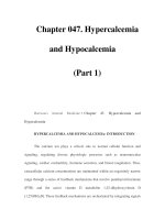
fatigue resistance, and fracture toughness. Typical specimens for these evaluations are shown in Fig. 1.
Fig. 1 Typical specimens for (a) tension testing, (b) notched tension testing, and (c) fracture toughness
testing
As will be highlighted throughout the discussion below, mechanical properties are highly dependent on
microstructure (e.g., grain size, phase distribution, second phase content), crystal structure type (i.e., the
arrangement of atoms), and elemental composition (e.g., alloying element content, impurity level). A common
illustration of the relationship between micro-structure and mechanical performance is the often observed
increase in yield stress with a decrease in grain size. Relationships like these between metal structure and
performance make mechanical property determination important for a wide variety of structural applications in
metal working, in failure analysis and prevention, and in materials development for advanced applications.
The following discussions are designed to briefly introduce typical relationships between metallurgical features
(such as crystal structures and microstructures) and the mechanical behavior of metals. Using basic examples,
deformation and fracture mechanisms are introduced. Typical properties measured during mechanical testing
are then related to these deformation mechanisms and the microstructures of metals.
Introduction to the Mechanical Behavior of Metals
Todd M. Osman, U.S. Steel Research; Joseph D. Rigney, General Electric Aircraft Engines
Structure of Metals
At the most basic level, metallic materials (as well as many nonmetallic ones) are typically crystalline solids,
although it is possible to produce amorphous metals (i.e., those with random atomic arrangement) in limited
quantities. The basic building block of the crystal lattice is the unit cell, some examples of which are shown in
Fig. 2(a) through (d). By repeating this arrangement in three dimensions, a crystal lattice is formed (see Fig 2.).
Although the arrangement of atoms in space can be of fourteen different types (or Bravais lattices), most metals
have face-centered cubic (fcc) (e.g., nickel, aluminum, copper, lead), body-centered cubic (bcc) (e.g., iron,
niobium, tungsten, molybdenum), or hexagonal close-packed (hcp) (e.g., titanium, magnesium, zinc) structures
as the unit cell structure. In very specific applications, materials can be used as single crystals where an entire
component is fabricated with one spatial orientation repeating throughout. More often than not, however,
engineering materials usually contain many crystals, or grains, as shown in Fig. 3. Depending on the
composition and thermomechanical processing, these grains are typically approximately 1 to 1000 μm in size
(although finer grain sizes can be produced via other techniques). While the crystal lattice within a grain is
consistent, the crystalline orientations vary from one grain to another.
Fig. 2 Examples of crystal structures. Unit cells: (a) simple cubic, (b) face-centered cubic, (c) body-
centered cubic, and (d) hexagonal close-packed. A crystal lattice: (e) three-dimensional simple cubic
Fig. 3 Examples of metallic microstructures: (a) Grains in an ultralow-carbon steel. Courtesy of U.S.
Steel. (b) Grains in pure niobium. (c) Precipitates at grain boundaries in niobium. (d) Discontinuously
reinforced metal matrix composite (silicon carbide particles in an aluminum matrix). Source:Ref 1. Note:
the grains in a–c are highlighted through the use of a chemical etchant.
Although some nonstructural applications may require pure metals because of certain physical property
advantages, additions of alloying elements are usually made for purposes of enhancing the mechanical
properties or other material characteristics (e.g., corrosion resistance). Metal alloys may consist of over ten
different elements in specific concentrations with the purpose to optimize a variety of properties. Minor
alloying additions typically do not alter the basic crystal structure as long as the elements remain in solid
solution. At sufficiently high concentrations, other phases (either with the same or different crystallographic
forms) may precipitate within the base metal (at grain boundaries or in the grain interior) as shown in Fig. 3.
Phase diagrams are used by metallurgists and materials engineers to understand equilibrium solubility limits in
engineering alloys and predict the phases which may form during thermomechanical processing (Ref 2). As will
be discussed later, solid solution elements and precipitates/particles are often used during alloy design to
improve the strength of a metal.
Metal matrix composites can also be fabricated in which dissimilar constituents (e.g., ceramics and
intermetallics) are incorporated into the metallic microstructure in order to enhance mechanical properties. The
example microstructure in Fig. 3 shows the reinforcement material to be dispersed throughout a continuous
metallic matrix with the metal representing 50% or greater of the total volume. Although the example shows
particles as the reinforcement, these materials can be designed with whiskers, short fibers, or long fibers (e.g.,
rods or filaments). Processing of these composites typically entails thGe incorporation of the reinforcement
material into the metal using ingot metallurgy or powder metallurgy techniques (Ref 3).
To the structural engineer, or in the macroscopic view (1×), most metals appear to be continuous,
homogeneous, and isotropic. Continuity assumes that structures do not contain voids; homogeneity assumes
that the microstructure (in views at ~100–1000×) and properties will be identical in all locations; isotropic
behavior assumes that the properties are identical in all orientations. While these assumptions have been used in
continuum mechanics to study the strength of materials and structures under load, engineering materials are
often inhomogeneous and anisotropic. While it is desirable to minimize such inhomogeneities, it is often
impossible to completely eliminate them. As discussed above, microstructural evaluation typically shows that
materials are comprised of an aggregate of grains of unique crystal structure and usually have second phases
(with different properties) dispersed throughout the parent structure. Typically, materials will have variations in
grain size, second phase size and distribution, and chemical composition, especially in binary and higher-order
alloys. Fabrication route may also play a key role in affecting the preferred crystallographic orientation (or
texture) of the grains, further contributing to the inhomogeneity and anisotropy of the microstructure. As will be
shown later, all of these microstructural features can greatly influence the properties measured during
mechanical testing.
When metals are subject to an external force, the response will depend on a number of factors. The type of
loading (e.g., tension, compression, shear, or combinations thereof) is one key factor. The strain rate,
temperature, nature of loading (monotonic versus alternating fatigue stresses), and presence of notches will also
affect the deformation response of the metal. Chemical influences, such as those associated with stress-
corrosion cracking (SCC) and hydrogen embrittlement, as well as physical alterations, such as those resulting
from radiation damage, may affect the deformation behavior. Finally, the specimen size and surface preparation
can influence the response observed during mechanical testing.
All of these factors are important and will be covered in various articles contained within this Volume. For
simplicity, the remainder of this section focuses on basic examples to illustrate the relationship between the
structure of a metal and the properties measured during mechanical testing.
References cited in this section
1. T.M. Osman, J.J. Lewandowski, and W.H. Hunt, Jr., Fabrication of Particulates Reinforced Metal
Composites, ASM International, 1990, p 209
2. Alloy Phase Diagrams, Vol 3, ASM Handbook, ASM International, 1992
3. D. Hull, An Introduction to Composite Materials, Cambridge University Press, 1975
Introduction to the Mechanical Behavior of Metals
Todd M. Osman, U.S. Steel Research; Joseph D. Rigney, General Electric Aircraft Engines
Deformation of Metals
The basic principles of deformation and fracture can be described through the use of a uniaxial tension (or
tensile) test. A detailed review of tension testing is presented later in this Volume; therefore, only a brief
description is presented for the purpose of introducing deformation and fracture mechanisms in metals. In
general, tensile tests are performed on cylindrical specimens (e.g., rods) or parallel-piped specimens (e.g., sheet
and plate) as shown in Fig. 1(a). The samples are loaded uniaxially, along the length of the specimen. The
applied load and extension (or change in length) of the sample are simultaneously measured.
The load and displacement are used to calculate engineering stress (s) and engineering strain (e) using Eq 1 and
Eq 2 :
S =P/A
0
(Eq 1)
e = ΔL/L
0
= (L
i
- L
0
)/L
0
(Eq 2)
where P is the applied load, L
0
is the initial gage length, L
i
is the instantaneous gage length, A
0
is the initial gage
cross-sectional area, and ΔL is the change in length. This analysis facilitates the comparison of results obtained
when testing samples that differ in thickness or geometry. (For validity, the samples need to conform to certain
design specifications as detailed later in this Volume.) Although these engineering values are adequate, the best
measures of the response of a material to loading are the true stress (σ) and true strain (ε) determined by the
instantaneous dimensions of the tensile specimen in Eq 3and Eq 4:
σ = P/A
i
= S(1 + e)
(Eq 3)
ε = ln (L
i
/L
0
) = (1 + e)
(Eq 4)
Because the instantaneous dimensions of the specimen are not typically measured, the true stress and true strain
may be estimated using the engineering stress and engineering strain (see Eq 1and Eq 2). It is noted that these
estimations are only valid during uniform elongation (see Fig. 4) and are not applicable throughout the entire
deformation range.
Fig. 4 Typical engineering stress-versus-engineering strain curve
Figure 4 depicts a typical engineering stress-versus-engineering strain curve produced in a uniaxial tension test.
In the initial stages of deformation, generally stress varies linearly with the strain. In this region, all deformation
is considered to be elastic because the sample will return to its original shape (i.e., dimensions) when the
applied stress is removed. If, however, the sample is not unloaded and deformation continues, the stress-versus-
strain curve becomes nonlinear. At this point, plastic deformation begins, causing a permanent elongation that
will not be recovered after unloading of the specimen. The stress at which a permanent deformation occurs is
called the elastic (or proportional) limit; however, an offset yield strength (e.g., 0.2% offset) is typically used to
quantify the onset of plastic deformation due to the ease and standardization of measurement. The tensile yield
strength of most alloys is on the order of 10
2
to 10
3
MPa:
• 135 to 480 MPa (20–70 ksi) for low-carbon steels
• 200 to 480 MPa (30–70 ksi) for aluminum alloys
• 1200 to 1650 MPa (175–240 ksi) for high-strength steels
To understand the different deformation modes, the structure of a metal must be considered. Elastic
deformation can be conceptualized by considering the bonds between individual atoms to be springs. As
mentioned above, a metal will stretch under the application of a load, but will return to its original shape after
the removal of that load if only elastic deformation occurs. Just as a spring constant relates the force to the
applied displacement (i.e., F = kx), the elastic modulus (E) relates the tensile stress to the applied tensile strain
(i.e., σ = Eε) and is simply the slope of the linear portion of the tensile stress-versus-tensile strain curve
produced in the tension test. Differences in the measured elastic moduli for different metals can therefore be
rationalized in part by the differences in the atomic bonds between the individual atoms within the crystal
lattice.
Plastic deformation results in a permanent change of shape, meaning that after the load is removed, the metal
will not return to its original dimensions. This implies a permanent displacement of atoms within the crystal
lattice. If a perfect crystal is assumed, this deformation could only occur by breaking all of the bonds at once
between two planes of atoms and then sliding one row (or plane) of atoms over another. Based on calculations
using the theoretical bond strengths, this process would result in yield strengths on the order of 10
4
to 10
5
MPa.
These strengths are much greater than those typically observed in actual metals (10
2
MPa); therefore,
deformation must occur via a different method.
Even under the most ideal crystal growth conditions, metals are not crystallographically perfect, as shown in
Fig. 2. Instead, the lattice may contain many imperfections. One such imperfection is an edge dislocation,
which, for simple cubic structures, can be considered to be the extra half plane of atoms shown schematically in
Fig. 5. Regions surrounding the dislocation may be a perfect array of atoms; however, the core of the
dislocation is shown as a localized distortion of the crystal lattice. While it may appear that this structure is
unfavorable, dislocations are necessary in metals. For example, at grain boundaries, dislocations are
“geometrically necessary” to allow the individual grains of different orientations to match.
Fig. 5 Schematic of an edge dislocation
The nature and quantity of the dislocations become an integral aspect of plastic deformation. There are two
generic types of dislocations, edge and screw, which are primarily differentiated by the manner in which each
may traverse through the metallic crystal (Ref 4). It is noted that dislocations of mixed character (i.e., partially
edge and partially screw) are most commonly observed. In general, both types of dislocations entail the
stepwise movement of the dislocation across the crystal lattice as opposed to the displacement of an entire plane
over another. This means that only one set of bonds is broken at a time as opposed to an entire plane. Motion
now occurs on a distinct set of slip systems, which are combinations of planes—denoted as {uvw} or (uvw)—
and directions—denoted as 〈hkl〉 or [hkl]—based on the closest packing of atoms within the crystal structure
(see Fig. 6 for an example of crystallographic planes and directions) (Ref 5). For example, motion will
predominantly occur on {111}〈110〉 slip systems in fcc metals and on {110}〈111〉, {112}〈111〉, or
{123}〈111〉 slip systems in bcc metals. As a result, differences in the plastic behavior of a given type of
metal (e.g., aluminum-killed versus fully stabilized steels) can in part be rationalized by which slip systems are
active during deformation. Likewise, differences in the properties between different metal types (e.g., bcc iron
versus fcc aluminum versus hcp titanium) can be related to the active slip systems in each metal and the relative
ease with which dislocations can move within the slip systems.