Volume 08 - Mechanical Testing and Evaluation Part 9 pot
Bạn đang xem bản rút gọn của tài liệu. Xem và tải ngay bản đầy đủ của tài liệu tại đây (3.24 MB, 150 trang )
36. R.A. Graham, Impact Techniques for the Study of Physical Properties of Solids under Shock Wave
Loading, J. Basic Eng. (Trans. ASME), Vol 89, 1967, p 911–918
40. E.G. Zukas, Shock-Wave Strengthening, Met. Eng. Q., Vol 6, 1966, p 1–20
45. L.M. Barker and R.E. Hollenbach, Interferometer Technique for Measuring the Dynamic Mechanical
Properties of Materials, Rev. Sci. Instrum., Vol 36, 196, p 1617–1620
46. G.E. Dieter, Metallurgical Effects of High-Intensity Shock Waves in Metals, Response of Metals to
High Velocity Deformation, P.G. Shewmon and V.F. Zackay, Ed., Interscience, 1961, p 409–446
47. G.R. Fowles, Experimental Technique and Instrumentation, Dynamic Response of Materials to Intense
Impulsive Loading, P.C. Chou and A.K. Hopkins, Ed., Air Force Materials Laboratory, Wright Patterson
Air Force Base, 1972, p 405–480
48. P.S. DeCarli and M.A. Meyers, Design of Uniaxial Shock Recovery Experiments, Shock Waves and
High Strain Rate Phenomena in Metals, M.A. Meyers and L.E. Murr, Ed., Plenum, 1981, p 341–373
49. R.G. McQueen and S.P. Marsh, High Explosive Systems for Equation-of-State Studies, Shock Waves in
Condensed Matter—1987, S.C. Schmidt and N.C. Holmes, Ed., Elsevier, 1988, p 107–110
50. M.A. Meyers, Dynamic Behavior of Materials, Wiley Interscience, 1994
51. G.E. Duvall, Shock Waves in the Study of Solids, Appl. Mech. Rev., Vol 15, 1962, p 849–854
52. E.G. Zukas, Shock-Wave Strengthening, Met. Eng. Q., Vol 6 (No. 2), 1966, p 1–20
53. J.N. Fritz and J.A. Morgan, An Electromagnetic Technique for Measuring Material Velocity, Rev. Sci.
Instrum., Vol 44, 1973, p 215–221
54. L.M. Barker and R.E. Hollenbach, Laser Interferometer for Measuring High Velocities of Any
Reflecting Surface, J. Appl. Phys., Vol 43, 1972, p 4669–4675
55. R.G. McQueen, J.W. Hopson, and J.N. Fritz, Optical Technique for Determining Rarefaction Wave
Velocities at Very High Pressures, Rev. Sci. Instrum., Vol 53, 1982, p 245–250
56. J.N. Fritz, C.E. Morris, R.S. Hixson, and R.G. McQueen, Liquid Sound Speeds at Pressure from the
Optical Analyzer Technique, High Pressure Science and Technology 1993, S.C. Schmidt, J.W. Shaner,
G.A. Samara, and M. Ross, Ed., American Institute of Physics, 1994, p 149–152
57. R.J. Clifton, Pressure Shear Impact and the Dynamic Plastic Response of Metals, Shock Waves in
Condensed Matter—1983, J.R. Asay, R.A. Graham, and G.K. Straub, Ed., North-Holland, 1984, p 105–
111
58. R.A. Graham and J.R. Asay, Measurement of Wave Profiles in Shock Loaded Solids, High Temp.—
High Press., Vol 10, 1978, p 355–390
59. G.R. Fowles, G.E. Duvall, J. Asay, P. Bellamy, F. Feistman, D. Grady, T. Michaels, and R. Mitchell,
Gas Gun for Impact Studies, Rev. Sci. Instrum., Vol 41, 1970, p 984–996
60. J.W. Taylor, Experimental Methods in Shock Wave Physics, Metallurgical Effects at High Strain Rates,
R.W. Rohde, B.M. Butcher, J.R. Holland, and C.H. Karnes, Ed., Plenum Press, 1973, p 107–128
61. G.T. Gray III, Deformation Twinning in Aluminum-4.8 wt.% Mg, Acta Metall., Vol 36, 1988, p 1745–
1754
62. G.T. Gray III, P.S. Follansbee, and C.E. Frantz, Effect of Residual Strain on the Substructure
Development and Mechanical Response of Shock-Loaded Copper, Mater. Sci. Eng. A, Vol 111, 1989, p
9–16
63. D.L. Paisley, Laser-Driven Miniature Flyer Plates for Shock Initiation of Secondary Explosives, Shock
Compression of Condensed Matter—1989, S.C. Schmidt, J.N. Johnson, and L.W. Davidson, Ed.,
Elsevier, 1990, p 733–736
64. D.E. Mikkola and R.N. Wright, Dislocation Generation and Its Relation to the Dynamic Plastic
Response of Shock Loaded Metals, Shock Waves in Condensed Matter—1983, J.R. Asay, R.A. Graham,
and G.K. Straub, North-Holland, 1984, p 415–418
65. S. Larouche, E.T. Marsh, and D.E. Mikkola, Strengthening Effects of Deformation Twins and
Dislocations Introduced by Short Duration Shock Pulses in Cu-8.7Ge, Metall. Trans. A, Vol 12, 1981 p
1777–1785
66. D.L. Paisley, Laser-Driven Miniature Plates for One-Dimensional Impacts at 0.5-ε6 km/s, Shock-Wave
and High-Strain-Rate Phenomena in Materials, M.A. Meyers, L.E. Murr, and K.P. Staudhammer, Ed.,
Marcel Dekker, 1992, p 1131–1141
67. D.L. Paisley, R.H. Warnes, and R.A. Kopp, Laser-Driven Flat Plate Impacts to 100 GPa with Sub-
Nanosecond Pulse Duration and Resolution for Material Property Studies, Shock Compression of
Condensed Matter—1991 S.C. Schmidt, R.D. Dick, J.W. Forbes, and D.G. Tasker, Ed., Elsevier, 1992,
p 825–828
68. J.H. Shea, A. Mazzella, and L. Avrami, Equation of State Investigation of Granular Explosives Using a
Pulsed Electron Beam, Proc. Fifth Symp. (Int.) on Detonation, Office of Naval Research, Arlington,
Virginia, 1970, p 351–359
69. F. Cottet and J.P. Romain, Formation and Decay of Laser-Generated Shock Waves, Phys. Rev. A, Vol
25, 1982, p 576–579
70. F. Cottet, J.P. Romain, R. Fabbro, and B. Faral, Measurements of Laser Shock Pressure and Estimate of
Energy Lost at 1.05μm Wavelength, J. Appl. Phys., Vol 55, 1984, p 4125–4127
71. F. Cottet and M. Boustie, Spallation Studies in Aluminum Targets Using Shock Waves Induced by
Laser Irradiation at Various Pulse Durations, J. Appl. Phys., Vol 66, 1989, p 4067–4073
72. T. de Rességuier and M. Hallouin, Stress Relaxation and Precursor Decay in Laser Shock-Loaded Iron,
J. Appl. Phys., Vol 84, 1998, p 1932–1938
73. T. de Rességuier and M. Deleignies, Spallation of Polycarbonate under Laser Driven Shocks, Shock
Waves, Vol 7, 1997, p 319–324
74. C.E. Ragan, Equation-of-State Experiments using Nuclear Explosions, Proc. Int. Symp. on Behaviour of
Condensed Matter at High Dynamic Pressures, Commissariat à l'Energie Atomique, Saclay, Paris,
1978, p 477
75. C.E. Ragan III, Shock Compression Measurements at 1 to 7 TPa, Phys. Rev. A, Vol 25, 1982, p 3360–
3375
76. R.F. Trunin, Shock Compressibility of Condensed Materials in Strong Shock Waves Generated by
Underground Nuclear Explosions, Physics Usp., Vol 37, 1994, p 1123–1145
Shock Wave Testing of Ductile Materials
George T. (Rusty) Gray III, Los Alamos National Laboratory
Design of Shock Recovery and Spallation Fixtures
The structure/property relationships in materials subjected to shock wave deformation are very difficult to
conduct and complex to interpret due to the dynamic nature of the shock process and the very short time of the
test. Due to these imposed constraints, the majority of real-time shock process measurements are limited to
studying the interactions of the transmitted wave arrival at the free surface or at target-window interfaces. To
augment these in situ wave profile measurements, shock recovery techniques were developed in the late 1950s
to experimentally assess the residual effects of shock wave compression, release, and shock-induced fracture
events on materials. The object of soft recovery experiments is to examine the terminal structure-property
relationships of a material that has been subjected to a known uniaxial shock history then returned to ambient
conditions without experiencing radial release tensile wave loading or collateral recovery strains. Tensile wave
interactions may be mostly mitigated by surrounding the sample with tightly fitting material of the same (or
nearly the same) shock impedance, both laterally and axially around the sample. This technique, termed
momentum trapping, has continued to evolve to prevent large radial release waves from entering the sample and
to prevent Hopkinson fracture (spallation) for a variety of sample configurations and shock-loading methods.
When ideally trapped, the residual strain, ε
res
, in the recovered sample (defined here as the final sample
thickness divided by the initial sample thickness) should be on the order of only a few percent. Since the
inception of shock recovery studies, the use of momentum trapping techniques has been successfully applied to
a large number of metallic systems and a more limited number of brittle solids.
Several review papers chronicle the development and design of shock recovery techniques (Ref 25, 26, 34, 40,
48, 77,and 78). To correctly assess the influence of shock wave deformation on ductile material structure and
properties, it is crucial to systematically control the experimental loading parameters and design the shock
fixtures to recover the test sample with minimum residual strain. With higher peak pressures (from 10 GPa, or
1.5 × 10
6
psi, upward) however, recovery of shock-loaded samples becomes increasingly difficult. For low-
pressure shocks, for example, a few times the Hugoniot elastic limit of the material, shock recovery is
straightforward independent of whether the shock is generated via HE, launcher impact, or radiation
impingement. At pressures in excess of 50 to 60 GPa (7.3 × 10
6
to 8.7 × 10
6
psi) recovery of bulk metallic
samples that have not been seriously compromised by significant shock heating and/or radial release strains is
nearly impossible. At shock pressures greater than 100 GPa (14.5 × 10
6
psi) recovery of samples is essentially
impossible. The techniques described below have been used for both HE- and launcher-driven shock recovery
experiments.
References cited in this section
25. G.T. Gray III, Influence of Shock-Wave Deformation on the Structure/Property Behavior of Materials,
High-Pressure Shock Compression of Solids, J.R. Asay and M. Shahinpoor, Ed., Springer-Verlag, 1993,
p 187–216
26. D.G. Doran and R.K. Linde, Shock Effects in Solids, Solid State Phys., Vol 19, 1966, p 230–290
34. G.T. Gray III, Shock Experiments in Metals and Ceramics, Shock-Wave and High-Strain-Rate
Phenomena in Materials, M.A. Meyers, L.E. Murr, and K.P. Staudhammer, Ed., Marcel-Dekker, 1992,
p 899–912
40. E.G. Zukas, Shock-Wave Strengthening, Met. Eng. Q., Vol 6, 1966, p 1–20
48. P.S. DeCarli and M.A. Meyers, Design of Uniaxial Shock Recovery Experiments, Shock Waves and
High Strain Rate Phenomena in Metals, M.A. Meyers and L.E. Murr, Ed., Plenum, 1981, p 341–373
77. R.N. Orava and R.H. Wittman, Techniques for the Control and Application of Explosive Shock Waves,
Proc. of Fifth Int. Conf. on High Energy Fabrication, University of Denver, 1975, p 1.1.1
78. M.A. Mogilevskii, Shock-Wave Loading of Specimens with Minimum Permanent Set, Combust.
Explos. Shock Waves, Vol 21, 1985, p 639–640
Shock Wave Testing of Ductile Materials
George T. (Rusty) Gray III, Los Alamos National Laboratory
Design Parameters for Flyer-Plate Experiments
The variation of the shock parameters (peak pressure and pulse duration) for recovery experiments can be
calculated using several simple formulations. Equations have been developed by Orava and Wittman (Ref 77)
for the design of recovery assemblies to achieve a given peak pressure and pulse duration and to protect the
sample from significant radial release and possible subsequent spallation. Design of the target-flyer variables to
achieve a given set of shock parameters in a shock recovery experiment is typically started by fixing the desired
peak shock pressure or true transient strain. This is linked to the fact that changes in peak shock pressure are
known to produce the most significant variation in post shock material structure-property relations (Ref 24, 25,
26, 28, 29, 30, 40, 42, 44, and 46). When the flyer plate and target assembly are the same material, called
symmetric impact, the material velocity behind the shock is exactly one half of the projectile velocity (Ref 77,
79):
V
p
= + = 2U
p
(Eq 1)
where V
p
is the projectile velocity and U
p
is the particle velocity partitioned between the driver plate, , and
the target, . Symmetric impact is generally preferred because it is most easily analyzed. In the case of
dissimilar materials, the particle velocity is divided according to the Hugoniot equations of each by the
impedance matching method (Ref 6). In this situation, complex release behavior is typical. Hugoniot data for a
wide range of materials can be found tabulated in Ref 79. The total equivalent or effective transient strain
induced in the sample due to this impact (encompassed as a sum of both the elastic and plastic compression and
elastic and plastic release portions of the shock process), ε
t
, is determined from the measured Hugoniot data,
which is the dynamic compressibility of the material as a function of pressure where V
0
and V are the initial and
final volumes of the material during the peak of the shock. Assuming that the residual strain remaining in the
sample after the shock release is zero (Ref 80), the transient or equivalent total strain imparted to the sample
due to the shock-loading impulse and release is given by:
(Eq 2)
In Fig. 4, a time-distance diagram of a symmetric impact by a driver plate with the target backed by a spall
plate is presented that ignores strength in the sample. The symmetry of impact is reflected in the similar slope
of the shock velocity, labeled U
s
, into the driver and target starting at time zero. The length of time the sample
remains at pressure is determined by combining the shock wave and release wave transit times through the
flyer. When the rarefaction wave reaches the flyer-target interface the pressure in the sample is released. The
release process is stretched in time in the form of a “rarefaction fan” due to the variation in longitudinal and
bulk wave speeds as a function of pressure. The pulse duration time, t
p
, at the front of the sample is
approximated by (Ref 77):
(Eq 3)
where d
D
is the driver plate thickness, is the shock velocity in the driver in shock, and are density of
driver at ambient pressure and under shock, respectively, and C
D
is the bulk sound speed in the compressed
(shocked-state) driver.
Fig. 4 Time-distance diagram of a symmetric shock wave impact
To assure the recovery specimen experiences uniaxial strain, that is, one-dimensional strain, in nature during
both loading and unloading it is necessary to protect the sample from radial release prior to uniaxial release.
Figure 4 schematically represents the time distance for a symmetric impact and the commensurate particle-
velocity time history, which would be visible to an interferometer, such as a VISAR, looking at the rear surface
of the sample assembly. If the driver plate and target assembly have the same dimension, then immediately
after the target assembly is impacted by the driver, radial release waves will be directed toward the interior of
the target assembly from the driver edges. In order to mitigate these lateral release waves, the sample within the
target assembly is surrounded by momentum traps comprised of rings or rails of material similar to the sample.
The width of the momentum trapping necessary must be sufficient to contain the total shock event in the flyer
and target of time, t
s
(Ref 77).
Given simple centered flow conditions where the driver, target, and momentum trapping materials are the same,
the minimum trapping width w is given by (Ref 77):
(Eq 4)
After the shock has traversed the sample, if it is not obstructed, it will reflect off the back surface of the
specimen as a release wave. This further complicates the loading history of the sample, indeed, if the rear
surface release wave is allowed to interact with the forward-moving release wave propagating in from the
driver that releases the sample to ambient pressure. In this case the two tensile release fans will meet and cause
spall fracture when the amplitude is above the dynamic tensile strength of the material. To prevent this from
occurring in the sample intended for postshock characterization, a spall plate is placed behind the sample to
isolate the release wave interactions in the spall plate, thereby protecting the sample spallation (Fig. 4). The
release time, t
R
, must be greater than or equal to the shock time. To protect the sample from spall interactions,
the spall plate thickness must equal or exceed the dimension (Ref 77):
(Eq 5)
As an example, a 10 GPa (1.5 × 10
6
psi), 1 μs pulse shock in a 5 mm (0.2 in.) thick high-purity copper sample
(symmetric impact, C
0
= 3.94 mm/μs, C = 4.425 mm/μs, U
s
= 4.326 mm/μs, and V/V
0
= 0.94) requires an
impactor traveling at 0.518 mm/μs (U
p
= 0.259 mm/μs) using a 2.25 mm (0.09 in.) thick copper impactor or
driver plate. The minimum momentum trapping and spall plate requirements are then calculated to be 10.45
mm (0.41 in.) and 10.56 mm (0.42 in.), respectively. While Eq 4 and 5 pertaining to the momentum trapping
and spallation requirements can be corrected for nonsymmetrical impact, this is not usually done. Internal
impedance mismatching within the assembly will cause additional wave reflections that compromise the simple
compression loading history of the sample. In instances where symmetric assembly design is impossible, as is
typically the case for most brittle solids, other techniques are necessary.
Figure 5 illustrates an example of a soft shock recovery fixture positioned on a shock support or impact
assembly for conducting shock recovery experiments on a gas- and/or propellant-driven launcher. Following
release of the shock through the sample, the two opposing release waves are designed to interact within the
spall plate, thereby isolating the sample from the high tensile stresses resulting from the overlap of the two
release fans. The central opening in the impact is thereafter utilized to facilitate the escape of the sample
assembly into the recovery catch tank area for deceleration. This central passageway additionally serves as a
mechanism to separate the sample assembly from the continued forward momentum on the projectile.
Inadequate assembly design to ensure a one-dimensional shock loading and release sequence has been shown to
alter the sample shock history and subsequent structure-property response due to the additional plastic work
imposed on the sample due to late-time radial release effects (Ref 80, 81). Careful attention to momentum
trapping of samples during shock recovery experimentation is therefore required if the structure-property
effects quantified in postmortem recovered samples are to be correlated to processes occurring during shock
loading.
Fig. 5 Schematic of a soft shock recovery fixture used on a gas/powder launcher assembly
References cited in this section
6. R.G. McQueen and S.P. Marsh, Equation of State for Nineteen Metallic Elements from Shock-Wave
Measurements to Two Megabars, J. Appl. Phys., Vol 31, 1960, p 1253–1269
24. C.S. Smith, Metallographic Studies of Metals after Explosive Shock, Trans. Metall. Soc. AIME, Vol
214, 1958, p 574–589
25. G.T. Gray III, Influence of Shock-Wave Deformation on the Structure/Property Behavior of Materials,
High-Pressure Shock Compression of Solids, J.R. Asay and M. Shahinpoor, Ed., Springer-Verlag, 1993,
p 187–216
26. D.G. Doran and R.K. Linde, Shock Effects in Solids, Solid State Phys., Vol 19, 1966, p 230–290
28. W.C. Leslie, Microstructural Effects of High Strain Rate Deformation, Metallurgical Effects at High
Strain Rates, R.W. Rhode, B.M. Butcher, J.R. Holland, and C.H. Karners, Ed., Plenum Press, 1973, p
571
29. L.E. Murr, Residual Microstructure—Mechanical Property Relationships in Shock-Loaded Metals and
Alloys, Shock Waves and High Strain Rate Phenomena in Metals, M.A. Meyers and L.E. Murr, Ed.,
Plenum, 1981, p 607–673
30. L.E. Murr, Metallurgical Effects of Shock and High-Strain-Rate Loading, Materials at High Strain
Rates, T.Z. Blazynski, Ed., Elsevier Applied Science, 1987, p 1–46
40. E.G. Zukas, Shock-Wave Strengthening, Met. Eng. Q., Vol 6, 1966, p 1–20
42. G.T. Gray III, Shock-Induced Defects in Bulk Materials, Materials Research Society Symp. Proc., Vol
499, 1998, p 87–98
44. S. Mahajan, Metallurgical Effects of Planar Shock Waves in Metals and Alloys, Phys. Status Solidi (a),
Vol 2, 1970, p 187–201
46. G.E. Dieter, Metallurgical Effects of High-Intensity Shock Waves in Metals, Response of Metals to
High Velocity Deformation, P.G. Shewmon and V.F. Zackay, Ed., Interscience, 1961, p 409–446
77. R.N. Orava and R.H. Wittman, Techniques for the Control and Application of Explosive Shock Waves,
Proc. of Fifth Int. Conf. on High Energy Fabrication, University of Denver, 1975, p 1.1.1
79. S.P. Marsh, LASL Shock Hugoniot Data, University of California Press, 1980
80. G.T. Gray III, P.S. Follansbee, and C.E. Frantz, Effect of Residual Strain on the Substructure
Development and Mechanical Response of Shock-Loaded Copper, Mater. Sci. Eng. A, Vol 111, 1989, p
9–16
81. A.L. Stevens and O.E. Jones, Radial Stress Release Phenomena in Plate Impact Experiments:
Compression-Release, J. Appl. Mech. (Trans. ASME), Vol 39, 1972, p 359–366
Shock Wave Testing of Ductile Materials
George T. (Rusty) Gray III, Los Alamos National Laboratory
Shock Recovery and Spallation Studies of Ductile Materials
As described previously, shock wave research includes analysis of samples subjected to an impact excursion to
examine the postmortem signature of the shock prestraining on the substructure and mechanical behavior of a
material in addition to damage evolution of a ductile material when subjected to a spallation uniaxial strain
loading history. A few examples of the types of experimental data and post mortem characterization results
typically quantified for both shock recovery and spallation research are introduced below.
Defect Generation during Shock Loading as Quantified Using Shock Recovery Experiments. In an ideal
isotropic homogeneous material, the passage of an elastic shock through a bulk material should leave behind no
lattice defects or imperfections. In practice, the severe loading path conditions imposed during a shock induce a
high density of defects in most materials (i.e., dislocations, point defects, and/or deformation twins). In
addition, during the shock process some materials may undergo a pressure-induced phase transition that affects
the material response. If the high-pressure phase persists upon release of pressure to ambient conditions
(although metastable) the postmortem substructure and mechanical response will also reflect the high-pressure
excursion. Interpretation of the results of shock wave effects on materials must therefore address all of the
details of the shock-induced deformation substructure in light of the operative metallurgical strengthening
mechanisms in the material under investigation and the experimental conditions under which the material was
deformed and recovered.
Microstructural examinations of shock-recovered samples have characterized the differing types of lattice
defects (dislocations, point defects, stacking faults, deformation twins, and, in some instances, high-pressure
phase products) generated during shock loading. The specific type of defect or defects activated and their
density and morphology within the shock-recovered material have, in turn, been correlated to the details of the
starting material chemistry, microstructure, and initial mechanical behavior or hardness, and the postmortem
mechanical behavior of the shock-prestrained material. Several in-depth reviews have summarized the
microstructural and mechanical response of shock-recovered metals and alloys (Ref 24, 25, 26, 28, 29, 30, 40,
42, 44, and 46). In general, the deformation substructures resulting from modest shock loading (up to 40 GPa,
or 6 × 10
6
psi) in metals are observed to be very uniformly distributed on a grain-to-grain scale.
The specific type of substructure developed in the shock in a given metal (e.g., dislocation cells, twins, or
faults) has been shown to critically depend on a number of factors. These include the crystal structure of the
metal or alloy, the relevant strengthening and deformation mechanisms in the material (such as alloying, grain
size, second phases, and interstitial content), temperature, stacking fault energy, and the shock-loading
parameters and experimental conditions. The overall substructure, while macroscopically uniform, can vary
within single grains. The substructure can consist of homogeneously distributed dislocation tangles or cells,
coarse planar slip, stacking faults, or twins (i.e., be locally heterogeneous). The type of substructure formed
depends on the deformation mechanisms operative in the specific material under the specific shock conditions.
These shock-induced microstructural changes in metallic systems in turn correlate with variations in the
postmortem mechanical properties. For example, the formation of deformation twins is facilitated in many
materials due to the very high strain rate during shock loading (Ref 61).
Shock loading in most metals and alloys has been shown to manifest greater hardening than quasi-static
deformation for the same total strain, particularly if the metal undergoes a polymorphic phase transition, such as
is observed in pure iron (Ref 42). Figure 6 compares the stress-strain response of annealed copper and annealed
tantalum samples that have been quasi-statically loaded with the quasi-static reloading responses of the samples
that have been shock prestrained. The shock-loaded stress-strain curves are plotted offset at the approximate
total transient shock strains, calculated as ; 1n (V/V
0
) for the shock (where V and V
0
are the compressed
volumes during the shock and the initial volumes, respectively). The offset curve for copper shows that the
reload behavior of the shock-prestrained sample (compared at an equivalent strain level) exhibits a reload flow
stress considerably higher than the unshocked copper. Other face-centered cubic metals and alloys (e.g., copper,
nickel, and aluminum) have been seen to exhibit similar behavior (Ref 24, 25, 26, 28, 29, 30, 40, 42, 44, and
46). On the contrary, the reload stress-strain response of tantalum shock prestrained to 7 and 20 GPa (1 and 3 ×
10
6
psi) is observed to display essentially no enhanced shock hardening in comparison to quasi-static loading to
an equivalent plastic strain.
Fig. 6 Stress-strain response of tantalum and copper illustrating the varied effect of shock prestraining
on postshock mechanical behavior
Spallation “Hopkinson Fracture” Studies of Ductile Materials. Spallation is the failure in a material due to the
action of tensile stresses developed in the interior of a sample or component through the overlap of two release
waves. Since the early work of Hopkinson (Ref 14), numerous researchers have studied this phenomena (Ref
15, 16, 20, 22, and 82). Early work by Rinehart (Ref 16), through systematic studies on a range of engineering
metals and alloys, demonstrated that a critical shock stress is needed to produce scabbing in a material. The
characteristic nature of this material quantity, as well as its importance to understanding interactions between
shock and the structure, continues to make spallation research of primary scientific and engineering interest. A
systematic representation of the idealized process of release wave overlap driving a material into a dynamic
tension, uniaxial strain, loading state is shown in Fig. 4. The elastic wave in this figure is assumed to be
negligible compared to the plastic I wave; no additional waves, such as a phase transition plastic II wave, are
present.
Measurements of the spall strength are based on analysis of the one-dimensional motion of compressible,
contiguous, condensed matter following the reflection of the shock pulse from the surface of the sample or
component. Figure 4 shows the shock trajectory that a sample undergoes during the path in a spallation
experiment. The shock that is imparted into the target through the jump in particle velocity upon impact with
the driver plate (or impactor) is thereafter unloaded through the release wave originating (in one dimension)
from the rear surface of the driver plate that diminishes the free surface velocity. If the impactor is sufficiently
thin, the rarefaction will overtake the shock because the release wave is traveling into the precompressed solid
and, therefore, its wave speed is higher than the shock velocity. In this case, the rarefaction will attenuate the
shock. This unloading wave is actually a fan of characteristics, which erodes the shock down toward ambient
pressure. This reduces the particle velocity from the peak Hugoniot State achieved by the imposed shock. For
thicker impactors, as in Fig. 4, the release fan arrives at the rear surface of the target well after the arrival of the
main shock. At the free rear surface of the target, the shock wave is reflected as an unloading wave that travels
back toward the interior of the target. Overlap of the release fans causes the material in the overlap region to be
loaded in tension. The maximum tensile stress is reached in the central area of the overlap of the two release
fans, termed the spall plane.
If the maximum tensile stress achieved exceeds the local fracture, strength damage is initiated in the target.
Fracture of the material at the spall plane causes the tensile stress to decrease rapidly to zero. As a result, a
compression wave forms in the matter adjacent to the spall plane region. These waves propagate in each
direction away from the spall plane. At the rear surface of the target, as in Fig. 4 where the particle velocity is
monitored, this compression wave is manifested as a jump in velocity. When the target spalls, a stress wave is
trapped between the spall plane and the rear of the target. Later reverberations of this stress wave lead to a
damped oscillation in the particle velocity record. This “ringing,” or period of oscillations, can be used to
determine the thickness of the spalled layer or scab produced.
Monitoring of the rear surface velocity of the sample or of the sample-window interface using a manganin
pressure gage or VISAR quantifies the sample particle velocity history. A representation of the correlation
between the spallation process within a sample and its manifestation on the sample rear surface or sample-
window surface is shown on the right side of Fig. 4. Measurements of the wave profile of a sample driven to
spall provides information on the time-dependent wave propagation and intersection processes leading to
damage evolution in a material if the tensile stresses are sufficiently high. Shock studies designed to study
spallation in a material therefore use the wave profile and, specifically, the details of the magnitude of the “pull-
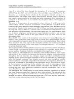
back” signal to quantify the energy necessary to nucleate and propagate damage. Figure 7 presents a VISAR
wave profile of high-purity zirconium subjected to spall loading (Ref 83). The arrow A identifies the Hugoniot
elastic limit for this material and the pull-back signal documents that this shock amplitude is sufficient to cause
damage evolution in this material; in this case, however, no scab was formed but rather only incipient spall.
Fig. 7 Rear surface velocity shock wave profile (developed using VISAR interferometry) showing
spallation in zirconium. Source: Ref 83
Profiles such as Fig. 7 provide quantitative data to compare with one-dimensional wave propagation finite-
difference and finite-volume code calculations that model dynamic fracture. Additional insight into the physics
and materials science controlling the process of spallation can be provided through examining the postshocked
and damaged samples, just as Hopkinson did in his first steel studies. Figure 8 shows a metallographic cross
section through an incipiently spalled high-purity tantalum sample following impact loading. In this example,
nearly spherical ductile voids are observed to have nucleated and grown, as a function of position from the
central fracture plane, and begun to coalesce under the imposed tensile stress history. Given sufficient tensile
stress amplitude and appropriate geometry, damage can lead to scab formation and, therefore, complete
separation of the sample into multiple pieces. Identification of the final fracture modes manifesting complete
separation can be obtained by soft recovering the scab formed and then examining its fracture surface. Figure 9
presents an example of a fracture surface of a spalled Ta-10W sample illustrating cleavage fracture behavior.
Fig. 8 Metallographic cross section of soft-recovered tantalum sample following spallation
Fig. 9 Scanning-electron microscopy (SEM) image of transgranular cleavage fracture in Ta-10W
spallation sample. Source: Ref 84
Quantification of the damage nucleation and evolution processes leading to dynamic failure provide the critical
physical insight into the micromechanisms governing this complex dynamic fracture process (Ref 22).
Documentation of the time- and stress-dependent loading parameters, specific damage mechanisms controlling
nucleation and growth, and the microstructural factors influencing these processes is needed to develop
physically based models describing the spallation of ductile materials.
References cited in this section
14. B. Hopkinson, The Pressure of a Blow, The Scientific Papers of Bertram Hopkinson, Cambridge
University Press, 1921, p 423–437
15. M.A. Meyers and C.T. Aimone, Dynamic Fracture (Spalling) of Metals, Prog. Mater. Sci., Vol 28,
1983, p 1–96
16. J.S. Rinehart, Scabbing of Metals under Explosive Attack: Multiple Scabbing, J. Appl. Phys., Vol 23,
1952, p 1229–1233
20. D.R. Curran, L. Seaman, and D.A. Shockey, Linking Dynamic Fracture to Microstructural Processes,
Shock Waves and High Strain-Rate Phenomena in Metals, M.A. Meyers and L.E. Murr, Ed., Plenum,
1981, p 129–167
22. A.K. Zurek and M.A. Meyers, Microstructural Aspects of Dynamic Failure, High Pressure Shock
Compression of Solids II: Dynamic Fracture and Fragmentation, L. Davison, D.E. Grady, and M.
Shahinpoor, Ed., Springer-Verlag, 1996, p 25–70
24. C.S. Smith, Metallographic Studies of Metals after Explosive Shock, Trans. Metall. Soc. AIME, Vol
214, 1958, p 574–589
25. G.T. Gray III, Influence of Shock-Wave Deformation on the Structure/Property Behavior of Materials,
High-Pressure Shock Compression of Solids, J.R. Asay and M. Shahinpoor, Ed., Springer-Verlag, 1993,
p 187–216
26. D.G. Doran and R.K. Linde, Shock Effects in Solids, Solid State Phys., Vol 19, 1966, p 230–290
28. W.C. Leslie, Microstructural Effects of High Strain Rate Deformation, Metallurgical Effects at High
Strain Rates, R.W. Rhode, B.M. Butcher, J.R. Holland, and C.H. Karners, Ed., Plenum Press, 1973, p
571
29. L.E. Murr, Residual Microstructure—Mechanical Property Relationships in Shock-Loaded Metals and
Alloys, Shock Waves and High Strain Rate Phenomena in Metals, M.A. Meyers and L.E. Murr, Ed.,
Plenum, 1981, p 607–673
30. L.E. Murr, Metallurgical Effects of Shock and High-Strain-Rate Loading, Materials at High Strain
Rates, T.Z. Blazynski, Ed., Elsevier Applied Science, 1987, p 1–46
40. E.G. Zukas, Shock-Wave Strengthening, Met. Eng. Q., Vol 6, 1966, p 1–20
42. G.T. Gray III, Shock-Induced Defects in Bulk Materials, Materials Research Society Symp. Proc., Vol
499, 1998, p 87–98
44. S. Mahajan, Metallurgical Effects of Planar Shock Waves in Metals and Alloys, Phys. Status Solidi (a),
Vol 2, 1970, p 187–201
46. G.E. Dieter, Metallurgical Effects of High-Intensity Shock Waves in Metals, Response of Metals to
High Velocity Deformation, P.G. Shewmon and V.F. Zackay, Ed., Interscience, 1961, p 409–446
61. G.T. Gray III, Deformation Twinning in Aluminum-4.8 wt.% Mg, Acta Metall., Vol 36, 1988, p 1745–
1754
82. L. Davison and R.A. Graham, Shock Compression of Solids, Phys. Rep., Vol 55, 1979, p 255–379
83. G.T. Gray III, N.K. Bourne, M.A. Zocher, P.J. Maudlin, and J.C.F. Millett, Influence of
Crystallographic Anisotropy on the Hopkinson Fracture “Spallation” of Zirconium, Shock Compression
of Condensed Matter—1999, AIP Conference Proceedings, M.D. Furnish, L.C. Chhabildas, and R.S.
Hixson, Ed., American Institute of Physics Press, Woodbury, NY, 2000, p 509–512
84. G.T. Gray III and A.D. Rollett, The High-Strain-Rate and Spallation Response on Tantalum, TA-10W
and T-111, High Strain Rate Behaviour of Refractory Metals and Alloys, R. Asfahani, E. Chen, and A.
Crowson, The Minerals, Metals and Materials Society, 1992, p 303–315
Shock Wave Testing of Ductile Materials
George T. (Rusty) Gray III, Los Alamos National Laboratory
Summary
Systematic shock-loading studies of materials, in which microstructural “real-time” shock physics processes,
mechanical property, and dynamic fracture effects are characterized quantitatively, provide important
diagnostic tools to understand the constitutive behavior of materials. A variety of loading techniques can be
used to shock load materials including HE-driven gas/powder launchers, exploding foils, laser-driven flyer
plates, and direct radiation impingement (including lasers and electron beams). Shock recovery experiments
provide a post mortem snapshot of the structure-property response of a material to the extreme conditions of
strain rate, triaxial stress, and temperature imposed by the shock for comparison with in situ wave profile and
shock-reload data. Postmortem characterization of shock-loaded materials will continue to contribute valuable
data to the understanding of real-time wave profile and shock wave data.
Shock Wave Testing of Ductile Materials
George T. (Rusty) Gray III, Los Alamos National Laboratory
Acknowledgments
This work was supported under the auspices of the United States Department of Energy. The author
acknowledges the assistance of B. Jacquez and C.P. Trujillo in conducting the shock recovery and spallation
testing. The author wishes to acknowledge R.S. Hixson and Dennis Hayes for critically reviewing this
manuscript.
Shock Wave Testing of Ductile Materials
George T. (Rusty) Gray III, Los Alamos National Laboratory
References
1. W.J.M. Rankine, On the Thermodynamic Theory of Waves of Finite Longitudinal Disturbance, Philos.
Trans. R. Soc. (London), Vol 160, 1870, p 277–288
2. J.N. Johnson and R. Chéret, Shock Waves in Solids: An Evolutionary Perspective, Shock Waves, Vol 9,
1999, p 193–200
3. M.H. Rice, R.G. McQueen, and J.M. Walsh, Compression of Solids by Strong Shock Waves, Solid State
Phys., Vol 6, 1958, p 1–63
4. J.M. Walsh and R.H. Christian, Equation of State of Metals from Shock Wave Measurements, Phys.
Rev., Vol 97, 1955, p 1544–1556
5. J.M. Walsh, M.H. Rice, R.G. McQueen, and F.L. Yarger, Shock-Wave Compressions of Twenty-Seven
Metals: Equations of State of Metals, Phys. Rev., Vol 108, 1957, p 196–216
6. R.G. McQueen and S.P. Marsh, Equation of State for Nineteen Metallic Elements from Shock-Wave
Measurements to Two Megabars, J. Appl. Phys., Vol 31, 1960, p 1253–1269
7. R.G. McQueen, Laboratory Techniques for Very High Pressures and the Behavior of Metals under
Dynamic Loading, Metallurgy at High Pressures and High Temperatures, K.A. Gschneidner, Jr., M.T.
Hepworth, and N.A.D. Parlee, Ed., Gordon and Breach, 1964, p 44–132
8. R.G. McQueen, S.P. Marsh, J.W. Taylor, J.N. Fritz, and W.J. Carter, The Equation of State of Solids
from Shock Wave Studies, High Velocity Impact Phenomena, R. Kinslow, Ed., Academic Press, 1970, p
293–417, 515–568
9. C.P. Morris, Los Alamos Shock Wave Profile Data, University of California Press, 1981
10. L.V. Altshuler, K.K. Krupnikov, and M.I. Brazhnik, Dynamic Compressibility of Metals under
Pressures from 400,000 to 4,000,000 Atmospheres, Sov. Phys. JETP, Vol 7, 1958, p 614–619
11. C.E. Anderson, J.S. Wilbeck, J.C. Hokanson, J.R. Asay, D.E. Grady, R.A. Graham, and M.E. Kipp,
Sandia Shock Compression Database, Shock Waves in Condensed Matter—1985, Y.M. Gupta, Ed.,
Plenum, 1986, p 185–190
12. L.V. Altshuler, R.F. Trunin, V.D. Urlin, V.E. Fortov, and A.I. Funtikov, Development of Dynamic
High-Pressure Techniques in Russia, Phys. Usp., Vol 42, 1999, p 261–280
13. B. Hopkinson, A Method of Measuring the Pressure Produced in the Detonation of High Explosives or
by the Impact of Bullets, Philos. Trans. R. Soc. (London) A, Vol 213, 1914, p 437–456
14. B. Hopkinson, The Pressure of a Blow, The Scientific Papers of Bertram Hopkinson, Cambridge
University Press, 1921, p 423–437
15. M.A. Meyers and C.T. Aimone, Dynamic Fracture (Spalling) of Metals, Prog. Mater. Sci., Vol 28,
1983, p 1–96
16. J.S. Rinehart, Scabbing of Metals under Explosive Attack: Multiple Scabbing, J. Appl. Phys., Vol 23,
1952, p 1229–1233
17. I.C. Skidmore, An Introduction to Shock Waves in Solids, Appl. Mater. Res., Vol 4, 1965, p 131–147
18. H. Kolsky, The Waves Generated by Brittle Fracture in Glass, Trans. Soc. Rheology, Vol 20, 1976, p
441–454
19. D.R. Curran, L. Seaman, and D.A. Shockey, Dynamic Failure of Solids, Phys. Rep., Vol 147, 1987, p
253–388
20. D.R. Curran, L. Seaman, and D.A. Shockey, Linking Dynamic Fracture to Microstructural Processes,
Shock Waves and High Strain-Rate Phenomena in Metals, M.A. Meyers and L.E. Murr, Ed., Plenum,
1981, p 129–167
21. D.R. Curran, L. Seaman, and D.A. Shockey, Dynamic Failure in Solids, Phys. Today, Vol 30 (No. 1),
1977, p 46–55
22. A.K. Zurek and M.A. Meyers, Microstructural Aspects of Dynamic Failure, High Pressure Shock
Compression of Solids II: Dynamic Fracture and Fragmentation, L. Davison, D.E. Grady, and M.
Shahinpoor, Ed., Springer-Verlag, 1996, p 25–70
23. P. Chevrier and J.R. Klepaczko, Spall Fracture: Mechanical and Microstructural Aspects, Eng. Fract.
Mech., Vol 63, 1999, p 273–294
24. C.S. Smith, Metallographic Studies of Metals after Explosive Shock, Trans. Metall. Soc. AIME, Vol
214, 1958, p 574–589
25. G.T. Gray III, Influence of Shock-Wave Deformation on the Structure/Property Behavior of Materials,
High-Pressure Shock Compression of Solids, J.R. Asay and M. Shahinpoor, Ed., Springer-Verlag, 1993,
p 187–216
26. D.G. Doran and R.K. Linde, Shock Effects in Solids, Solid State Phys., Vol 19, 1966, p 230–290
27. S. Mahajan, Metallurgical Effects of Planar Shock Waves in Metals and Alloys, Phys. Status Solidi (a),
Vol 2, 1970, p 187–201
28. W.C. Leslie, Microstructural Effects of High Strain Rate Deformation, Metallurgical Effects at High
Strain Rates, R.W. Rhode, B.M. Butcher, J.R. Holland, and C.H. Karners, Ed., Plenum Press, 1973, p
571
29. L.E. Murr, Residual Microstructure—Mechanical Property Relationships in Shock-Loaded Metals and
Alloys, Shock Waves and High Strain Rate Phenomena in Metals, M.A. Meyers and L.E. Murr, Ed.,
Plenum, 1981, p 607–673
30. L.E. Murr, Metallurgical Effects of Shock and High-Strain-Rate Loading, Materials at High Strain
Rates, T.Z. Blazynski, Ed., Elsevier Applied Science, 1987, p 1–46
31. D. Raybould and T.Z. Blazynski, Non-Metallic Materials under Shock Loading, Materials at High
Strain Rates, T.Z. Blazynski, Ed., Elsevier Applied Science, 1987, p 71–132
32. K.P. Staudhammer, Shock Wave Effects and Metallurgical Parameters, Impact Loading and Dynamic
Behaviour of Materials, C.Y. Chiem, H D. Kunze, and L.W. Meyer, Ed., DGM
Informationsgesellschaft mbH, 1988, p 93–112
33. G.T. Gray III, Shock Recovery Experiments: An Assessment, Shock Compression of Condensed
Matter—1989, S.C. Schmidt, J.N. Johnson, and L.W. Davidson, Ed., Elsevier, 1990, p 407–414
34. G.T. Gray III, Shock Experiments in Metals and Ceramics, Shock-Wave and High-Strain-Rate
Phenomena in Materials, M.A. Meyers, L.E. Murr, and K.P. Staudhammer, Ed., Marcel-Dekker, 1992,
p 899–912
35. G.T. Gray III, Shock Loading Response of Advanced Materials, High Pressure Science and Technology
1993, S.C. Schmidt, J.W. Shaner, G.A. Samara, and M. Ross, Ed., American Institute of Physics, 1994,
p 1161–1164
36. R.A. Graham, Impact Techniques for the Study of Physical Properties of Solids under Shock Wave
Loading, J. Basic Eng. (Trans. ASME), Vol 89, 1967, p 911–918
37. G.T. Gray III, R.S. Hixson, and C.E. Morris, Bauschinger Effect During Shock Loading, Shock
Compression of Condensed Matter—1991, S.C. Schmidt, R.D. Dick, J.W. Forbes, and D.G. Tasker, Ed.,
Elsevier, 1992, p 427–430
38. J.N. Johnson, R.S. Hixson, D.L. Tonks, and G.T. Gray III, Shock Compression and Quasielastic Release
in Tantalum, High Pressure Science and Technology 1993, S.C. Schmidt, J.W. Shaner, G.A. Samara,
and M. Ross, Ed., American Institute of Physics, 1994, p 1095–1098
39. J.N. Johnson, G.T. Gray III, and N.K. Bourne, Effect of Pulse Duration and Strain Rate on Incipient
Spall Fracture in Copper, J. Appl. Phys., Vol 86, 1999, p 4892–4901
40. E.G. Zukas, Shock-Wave Strengthening, Met. Eng. Q., Vol 6, 1966, p 1–20
41. C.M. Fowler, F.S. Minshall, and E.G. Zukas, A Metallurgical Method for Simplifying the
Determination of Hugoniot Curves for Iron Alloys in the Two-Wave Region, Response of Metals to
High Velocity Deformation, P.G. Shewmon and V.F. Zackay, Ed., Interscience, 1961, p 275–308
42. G.T. Gray III, Shock-Induced Defects in Bulk Materials, Materials Research Society Symp. Proc., Vol
499, 1998, p 87–98
43. E. Hornbogen, Shock-Induced Dislocations, Acta Metall., Vol 10, 1962, p 978–980
44. S. Mahajan, Metallurgical Effects of Planar Shock Waves in Metals and Alloys, Phys. Status Solidi (a),
Vol 2, 1970, p 187–201
45. L.M. Barker and R.E. Hollenbach, Interferometer Technique for Measuring the Dynamic Mechanical
Properties of Materials, Rev. Sci. Instrum., Vol 36, 196, p 1617–1620
46. G.E. Dieter, Metallurgical Effects of High-Intensity Shock Waves in Metals, Response of Metals to
High Velocity Deformation, P.G. Shewmon and V.F. Zackay, Ed., Interscience, 1961, p 409–446
47. G.R. Fowles, Experimental Technique and Instrumentation, Dynamic Response of Materials to Intense
Impulsive Loading, P.C. Chou and A.K. Hopkins, Ed., Air Force Materials Laboratory, Wright Patterson
Air Force Base, 1972, p 405–480
48. P.S. DeCarli and M.A. Meyers, Design of Uniaxial Shock Recovery Experiments, Shock Waves and
High Strain Rate Phenomena in Metals, M.A. Meyers and L.E. Murr, Ed., Plenum, 1981, p 341–373
49. R.G. McQueen and S.P. Marsh, High Explosive Systems for Equation-of-State Studies, Shock Waves in
Condensed Matter—1987, S.C. Schmidt and N.C. Holmes, Ed., Elsevier, 1988, p 107–110
50. M.A. Meyers, Dynamic Behavior of Materials, Wiley Interscience, 1994
51. G.E. Duvall, Shock Waves in the Study of Solids, Appl. Mech. Rev., Vol 15, 1962, p 849–854
52. E.G. Zukas, Shock-Wave Strengthening, Met. Eng. Q., Vol 6 (No. 2), 1966, p 1–20
53. J.N. Fritz and J.A. Morgan, An Electromagnetic Technique for Measuring Material Velocity, Rev. Sci.
Instrum., Vol 44, 1973, p 215–221
54. L.M. Barker and R.E. Hollenbach, Laser Interferometer for Measuring High Velocities of Any
Reflecting Surface, J. Appl. Phys., Vol 43, 1972, p 4669–4675
55. R.G. McQueen, J.W. Hopson, and J.N. Fritz, Optical Technique for Determining Rarefaction Wave
Velocities at Very High Pressures, Rev. Sci. Instrum., Vol 53, 1982, p 245–250
56. J.N. Fritz, C.E. Morris, R.S. Hixson, and R.G. McQueen, Liquid Sound Speeds at Pressure from the
Optical Analyzer Technique, High Pressure Science and Technology 1993, S.C. Schmidt, J.W. Shaner,
G.A. Samara, and M. Ross, Ed., American Institute of Physics, 1994, p 149–152
57. R.J. Clifton, Pressure Shear Impact and the Dynamic Plastic Response of Metals, Shock Waves in
Condensed Matter—1983, J.R. Asay, R.A. Graham, and G.K. Straub, Ed., North-Holland, 1984, p 105–
111
58. R.A. Graham and J.R. Asay, Measurement of Wave Profiles in Shock Loaded Solids, High Temp.—
High Press., Vol 10, 1978, p 355–390
59. G.R. Fowles, G.E. Duvall, J. Asay, P. Bellamy, F. Feistman, D. Grady, T. Michaels, and R. Mitchell,
Gas Gun for Impact Studies, Rev. Sci. Instrum., Vol 41, 1970, p 984–996
60. J.W. Taylor, Experimental Methods in Shock Wave Physics, Metallurgical Effects at High Strain Rates,
R.W. Rohde, B.M. Butcher, J.R. Holland, and C.H. Karnes, Ed., Plenum Press, 1973, p 107–128
61. G.T. Gray III, Deformation Twinning in Aluminum-4.8 wt.% Mg, Acta Metall., Vol 36, 1988, p 1745–
1754
62. G.T. Gray III, P.S. Follansbee, and C.E. Frantz, Effect of Residual Strain on the Substructure
Development and Mechanical Response of Shock-Loaded Copper, Mater. Sci. Eng. A, Vol 111, 1989, p
9–16
63. D.L. Paisley, Laser-Driven Miniature Flyer Plates for Shock Initiation of Secondary Explosives, Shock
Compression of Condensed Matter—1989, S.C. Schmidt, J.N. Johnson, and L.W. Davidson, Ed.,
Elsevier, 1990, p 733–736
64. D.E. Mikkola and R.N. Wright, Dislocation Generation and Its Relation to the Dynamic Plastic
Response of Shock Loaded Metals, Shock Waves in Condensed Matter—1983, J.R. Asay, R.A. Graham,
and G.K. Straub, North-Holland, 1984, p 415–418
65. S. Larouche, E.T. Marsh, and D.E. Mikkola, Strengthening Effects of Deformation Twins and
Dislocations Introduced by Short Duration Shock Pulses in Cu-8.7Ge, Metall. Trans. A, Vol 12, 1981 p
1777–1785
66. D.L. Paisley, Laser-Driven Miniature Plates for One-Dimensional Impacts at 0.5-ε6 km/s, Shock-Wave
and High-Strain-Rate Phenomena in Materials, M.A. Meyers, L.E. Murr, and K.P. Staudhammer, Ed.,
Marcel Dekker, 1992, p 1131–1141
67. D.L. Paisley, R.H. Warnes, and R.A. Kopp, Laser-Driven Flat Plate Impacts to 100 GPa with Sub-
Nanosecond Pulse Duration and Resolution for Material Property Studies, Shock Compression of
Condensed Matter—1991 S.C. Schmidt, R.D. Dick, J.W. Forbes, and D.G. Tasker, Ed., Elsevier, 1992,
p 825–828
68. J.H. Shea, A. Mazzella, and L. Avrami, Equation of State Investigation of Granular Explosives Using a
Pulsed Electron Beam, Proc. Fifth Symp. (Int.) on Detonation, Office of Naval Research, Arlington,
Virginia, 1970, p 351–359
69. F. Cottet and J.P. Romain, Formation and Decay of Laser-Generated Shock Waves, Phys. Rev. A, Vol
25, 1982, p 576–579
70. F. Cottet, J.P. Romain, R. Fabbro, and B. Faral, Measurements of Laser Shock Pressure and Estimate of
Energy Lost at 1.05μm Wavelength, J. Appl. Phys., Vol 55, 1984, p 4125–4127
71. F. Cottet and M. Boustie, Spallation Studies in Aluminum Targets Using Shock Waves Induced by
Laser Irradiation at Various Pulse Durations, J. Appl. Phys., Vol 66, 1989, p 4067–4073
72. T. de Rességuier and M. Hallouin, Stress Relaxation and Precursor Decay in Laser Shock-Loaded Iron,
J. Appl. Phys., Vol 84, 1998, p 1932–1938
73. T. de Rességuier and M. Deleignies, Spallation of Polycarbonate under Laser Driven Shocks, Shock
Waves, Vol 7, 1997, p 319–324
74. C.E. Ragan, Equation-of-State Experiments using Nuclear Explosions, Proc. Int. Symp. on Behaviour of
Condensed Matter at High Dynamic Pressures, Commissariat à l'Energie Atomique, Saclay, Paris,
1978, p 477
75. C.E. Ragan III, Shock Compression Measurements at 1 to 7 TPa, Phys. Rev. A, Vol 25, 1982, p 3360–
3375
76. R.F. Trunin, Shock Compressibility of Condensed Materials in Strong Shock Waves Generated by
Underground Nuclear Explosions, Physics Usp., Vol 37, 1994, p 1123–1145
77. R.N. Orava and R.H. Wittman, Techniques for the Control and Application of Explosive Shock Waves,
Proc. of Fifth Int. Conf. on High Energy Fabrication, University of Denver, 1975, p 1.1.1
78. M.A. Mogilevskii, Shock-Wave Loading of Specimens with Minimum Permanent Set, Combust.
Explos. Shock Waves, Vol 21, 1985, p 639–640
79. S.P. Marsh, LASL Shock Hugoniot Data, University of California Press, 1980
80. G.T. Gray III, P.S. Follansbee, and C.E. Frantz, Effect of Residual Strain on the Substructure
Development and Mechanical Response of Shock-Loaded Copper, Mater. Sci. Eng. A, Vol 111, 1989, p
9–16
81. A.L. Stevens and O.E. Jones, Radial Stress Release Phenomena in Plate Impact Experiments:
Compression-Release, J. Appl. Mech. (Trans. ASME), Vol 39, 1972, p 359–366
82. L. Davison and R.A. Graham, Shock Compression of Solids, Phys. Rep., Vol 55, 1979, p 255–379
83. G.T. Gray III, N.K. Bourne, M.A. Zocher, P.J. Maudlin, and J.C.F. Millett, Influence of
Crystallographic Anisotropy on the Hopkinson Fracture “Spallation” of Zirconium, Shock Compression
of Condensed Matter—1999, AIP Conference Proceedings, M.D. Furnish, L.C. Chhabildas, and R.S.
Hixson, Ed., American Institute of Physics Press, Woodbury, NY, 2000, p 509–512
84. G.T. Gray III and A.D. Rollett, The High-Strain-Rate and Spallation Response on Tantalum, TA-10W
and T-111, High Strain Rate Behaviour of Refractory Metals and Alloys, R. Asfahani, E. Chen, and A.
Crowson, The Minerals, Metals and Materials Society, 1992, p 303–315
Low-Velocity Impact Testing
Horacio Dante Espinosa, Northwestern University, Sia Nemat-Nasser, University of California, San Diego
Introduction
IMPACT TESTS are used to study dynamic deformation and failure modes of materials. Low-velocity impact
techniques can be classified as plate-on-plate, rod-on-plate, plate-on-rod, or rod-on-rod experiments. Two types
of plate-on-plate impact tests have been developed: wave propagation experiments and thin-layer high-strain-
rate experiments. The plate-on-plate experiments are further classified as nonrecovery or recovery experiments.
The focus of this article is on plate-on-plate experimental techniques. At the end of this article, rod-on-plate and
plate-on-rod experiments are briefly examined.
Observation of plane waves in materials provides a powerful method for understanding and quantifying their
dynamic response (Ref 1, 2, 3, 4, 5, 6, 7, 8, and 9) and failure modes (Ref 10, 11, 12, 13, 14, 15, 16, 17, 18, 19,
20, 21, 22, 23, 24, 25, 26, 27, 28, and 29). Plate impact experiments are used to generate such plane waves (Ref
30, 31, and 32). These experiments provide controlled extreme stress-state loading conditions, involving one-
dimensional stress-pulse propagation. The recovery configurations in plate-on-plate impact experiments are
performed with the objective of examining the microstructural changes in the specimen after it is subjected to
loading under a uniaxial strain condition. The experiments are designed to achieve a controlled plane-wave
loading of the specimens. In practice, this is limited by the finite size of the plates employed, which generate
radial release waves. This has the potential for significant contribution to the damage processes by introducing
causes other than the uniaxial straining of the material. Hence, this aspect of the plate impact experiment has
been a subject of considerable research in the past (Ref 11, 13, 33, 34, 35, 36, 37, 38, and 39).
The plate impact experiments are performed in two main modes: normal impact and pressure-shear, or oblique,
impact. Both modes have been specialized to several new configurations to achieve different aspects of control
over the imposed loading. In these experiments, the time histories of the stress waves are recorded and used to
infer the response of the specimen with the goal of constitutive modeling. To enable the formulation of correct
constitutive behavior for the considered material, knowledge of the micromechanisms of deformation that occur
during the passage of the stress waves is necessary. Such knowledge is also necessary for damage-evolution
studies. Hence, it is important that the specimen is recovered after it is subjected to a well-characterized loading
pulse so that it can be analyzed for any changes in its microstructure. This is achieved in the normal plate
impact mode by using an impedance-matched momentum trap behind the specimen (Ref 1, 7, and 11). Ideally,
the momentum-trap plate captures the momentum of the loading pulse and flies away, leaving the specimen at
rest.
Initially, the recovery technique was developed for the normal plate experiments (Ref 1, 38, and 39), and it has
been implemented in the pressure-shear mode to study shear stress-sensitive, high-rate deformation
mechanisms. The difficulty in conducting pressure-shear recovery experiments stems from the fact that both the
shear and longitudinal momenta must be trapped and that there is a large difference in the longitudinal and
shear wave velocities for any given material. To overcome this problem, one idea that had been proposed was
to use a composite flyer made of two plates of the same material that are separated by a thin layer of a low
shear resistance film, such as a lubricant (Ref 40, 41). This design would enable the shear pulse to be unloaded
at the interface, while the pressure pulse would be transmitted to the next plate. The pressure pulse would return
to the specimen momentum-trap interface as an unloading wave after the unloading of the shear wave has taken
place. The thickness of the momentum-trap plate is chosen such that the normal unloading wave from its rear
surface arrives at this interface much later, and hence, the momentum trap would separate just as in the normal
recovery experiment, but after trapping both the shear and normal momenta.
The plate impact experiments can be performed at different temperatures by providing temperature-control
facilities in the test chamber. This may consist of a high-frequency (0.5 MHz) induction heating system, for
high-temperature tests, or a cooling ring with liquid nitrogen circulating through an inner channel, for low-
temperature experiments (Ref 42, 43, and 44).
Confined and unconfined rod experiments have been performed (Ref 45, 46) with the aim of extending the
uniaxial strain deformation states imposed in the plate impact experiments. The bar impact and pressure-shear
experiments provide a measurement of yield stress at rates of 10
3
to 10
5
/s
-1
. They also allow the experimental
verification and validation of constitutive models and numerical solution schemes under two-dimensional states
of deformation. In-material stress measurements, with embedded manganin gages, are used to obtain axial and
lateral stress histories. Stress decay, pulse duration, release structure, and wave dispersion are well defined in
these plate and rod experiments.
References cited in this section
1. P. Kumar and R.J. Clifton, Dislocation Motion and Generation in LiF Single Crystals Subjected to
Plate-Impact, J. Appl. Phys. ,Vol 50 (No. 7), 1979, p 4747–4762
2. K.S. Kim and R.J. Clifton, Pressure-Shear Impact of 6061-T6 Aluminum and Alpha-Titanium, J. Appl.
Mech., Vol 47, 1980, p 11–16
3. A. Gilat and R.J. Clifton, Pressure-Shear Waves in 6061-T6 Aluminum and Alpha-Titanium, J. Mech.
Phys. Solids, Vol 33 (No. 3), 1985, p 263–284
4. C.H. Li, “A Pressure-Shear Experiment for Studying the Dynamic Plastic Response of Metals and Shear
Strain Rates of 10
5
s
-1
,” Ph.D. thesis, Brown University, Providence, RI, 1982
5. R.J. Clifton and R.W. Klopp, Pressure-Shear Plate Impact Testing, Mechanical Testing, Vol 8, ASM
Handbook, 9th ed., ASM International, 1985, p 230–239
6. K.T. Ramesh and R.J. Clifton, A Pressure-Shear Plate Impact Experiment for Studying the Rheology of
Lubricants at High Pressures and High Strain Rates, J. Tribology, 1987, Vol 109, p 215
7. H.D. Espinosa and R.J. Clifton, Plate Impact Experiments for Investigating Inelastic Deformation and
Damage of Advanced Materials, Symposium on Experiments in Micromechanics of Fracture-Resistant
Materials (ASME Winter Annual Meeting), 1–6 Dec 1991 (Atlanta, GA), K.S. Kim, Ed., 1991, p 37–56
8. J.C. Escobar and R.J. Clifton, On Pressure-Shear Plate Impact for Studying the Kinetics of Stress-
Induced Phase Transformations, Mater. Sci. Eng. A: Structural Materials: Properties, Microstructure &
Processing, No. 1–2, 1 Oct 1993, p 125–142
9. Y. Sano, S N. Chang, M.A. Meyers, and S. Nemat-Nasser, Identification of Stress Induced Nucleation
Sites for Martensite in Fe-31.8wt%Ni-0.02wt%C Alloy, Acta Metall. Mater., Vol 40 (No. 2), 1992, p
413–417
10. G. Ravichandran and R.J. Clifton, Dynamic Fracture under Plane Wave Loading. Int. J. Fract., Vol 40
(No. 3), 1989, p 157–201
11. G. Raiser, R.J. Clifton, and M. Ortiz, A Soft-Recovery Plate Impact Experiment for Studying
Microcracking in Ceramics, Mech. Mater., Vol 10, 1990, p 43–58
12. H.D. Espinosa, G. Raiser, R.J. Clifton, and M. Ortiz, Inelastic Mechanisms in Dynamically Loaded
Ceramics, Mechanics Computing in 1990s and Beyond, ASCE Proceedings, 20–22 May 1991
(Columbus, OH), H. Adeli and R. Sierakowski, Ed., American Society of Civil Engineers, 1991, p 293–
297
13. H.D. Espinosa, G. Raiser, R.J. Clifton, and M. Ortiz, Performance of the Star-Shaped Flyer in the Study
of Brittle Materials: Three Dimensional Computer Simulations and Experimental Observations, J. Appl.
Phys., Vol 72 (No. 8), 1992, p 3451–3457
14. H.D. Espinosa, G. Raiser, R.J. Clifton, and M. Ortiz, Experimental Observations and Numerical
Modeling of Inelasticity in Dynamically Loaded Ceramics, J. Hard Mater., Vol 3 (No. 3–4), 1992, p
285–313
15. V. Prakash, L.B. Freund, and R.J. Clifton, Stress Wave Radiation from a Crack Tip during Dynamic
Initiation, J. Appl. Mech. (Trans. ASME), Vol 59 (No. 2), June 1992, p 356–365
16. A.R. Machcha and S. Nemat-Nasser, Pressure-Shear Recovery Experiments, Mech. Mater., Vol 18,
1994, p 49–53
17. H.D. Espinosa, M. Mello, and Y. Xu, A Desensitized Displacement Interferometer Applied to Impact
Recovery Experiments, J. Appl. Phys. Lett., Vol 69 (No. 21), 1996, p 3161–3163
18. H.D. Espinosa, A. Patanella, and Y. Xu, Dynamic Compression-Shear Loading of Brittle Materials with
Specimen Recovery, Proceedings of the 11th Int. Conf. on Experimental Mechanics, 24–28 Aug 1998
(Oxford, UK), I.M. Allison, Ed., 1998, p 223–229
19. H.D. Espinosa, A. Patanella, and Y. Xu, Dynamic Compression-Shear Response of Brittle Materials
with Specimen Recovery, to appear in Exp. Mech., 2000
20. M. Zhou, A. Needleman, and R.J. Clifton, Finite Element Simulations of Shear Localization in Plate
Impact, J. Mech. Phys. Solids, Vol 42 (No. 3), 1994, p 423–458
21. H.D. Espinosa, On the Dynamic Shear Resistance of Ceramic Composites and its Dependence on
Applied Multiaxial Deformation, Int. J. Solids Struct., Vol 32 (No. 21), 1995, p 3105–3128
22. P.D. Zavattieri, P.V. Raghuram, and H.D. Espinosa, A Computational Model of Ceramic
Microstructures Subjected to Multi-Axial Dynamic Loading, to appear in J. Mech. Phys. Solids, 2000
23. A.R. Machcha and S. Nemat-Nasser, Effects of Geometry in Pressure-Shear and Normal Plate Impact
Experiments: Three-Dimensional Finite Element Simulations and Experimental Observations, J. Appl.
Phys., Vol 80 (No. 6), 1996, p 3267–3274
24. H.D. Espinosa, Y. Xu, and N.S. Brar, Micromechanics of Failure Waves in Glass: Experiments, J. Am.
Ceram. Soc., Vol 80 (No. 8), 1997, p 2061–2073
25. H.D. Espinosa, Y. Xu, and N.S. Brar, Micromechanics of Failure Waves in Glass: Modeling, J. Am.
Ceram. Soc., Vol 80 (No. 8), 1997, p 2074–2085
26. H.D. Espinosa, Y. Xu, and H C. Lu, Inelastic Behavior of Fiber Composites Subjected to Out-of-Plane
High Strain Rate Shearing, Acta Mater., Vol 45 (No. 11), 1997, p 4855–4865
27. H.V. Arrieta and H.D. Espinosa, High and Low Temperature Dynamic Testing of Advanced Materials,
Shock Compression of Condensed Matter, APS Conference (Snowbird, UT), American Physics Society,
1999
28. H.D. Espinosa, P.D. Zavattieri, and G.L. Emore, Adaptive FEM Computation of Geometric and
Material Nonlinearities with Application to Brittle Failure, Mech. Mater., H.D. Espinosa and R.J.
Clifton, Ed., Vol 29, 1998, p 275–305
29. H.D. Espinosa, P.D. Zavattieri, and S. Dwivedi, A Finite Deformation Continuum/Discrete Model for
the Description of Fragmentation and Damage in Brittle Materials, J. Mech. Phys. Solids, Vol 46 (No.
10), 1998, p 1909–1942
30. A.S. Abou-Sayes, R.J. Clifton, and L. Hermann, The Oblique Plate Impact Experiment, Exp. Mech., Vol
16, 1976, p 127–132
31. L.C. Chhabildas and J.W. Swegle, Dynamic Pressure-Shear Loading of Materials Using Anistropic
Crystals, J. Appl. Phys., Vol 51, 1980, p 4799–4807
32. T. Nicholas and S.J. Bless, High Strain Rate Tension Testing, Mechanical Testing, Vol 8, ASM
Handbook, 9th ed., ASM International, 1985, p 208–214
33. W.F. Hartman, Determination of Unloading Behavior of Uniaxially Strained 6061-T Aluminum from
Residual Strain Measurements, J. Appl. Phys., Vol 35, 1964, p 2090
34. R. Dandliker and J F. Willemin, Measuring Microvibrations by Heterodyne Speckle Interferometry,
Opt. Lett., Vol 6, 1981, p 165
35. J.E. Vorthman and G.E. Duvall, Dislocations in Shocked and Recovered LiF, J. Appl. Phys., Vol 53,
1982, p 3607–3615
36. S N. Chang, D T. Chung, G. Ravichandran, and S. Nemat-Nasser, Plate Impact Experiments on Mg-
PSZ and Improved Target Configuration, Proceedings of 1989 APS Topical Conference on Shock
Compresssion of Condensed Matter, 14–17 Aug 1989, S.C. Schmidt, J.N. Johnson, and L.W. Davidson,
Ed., American Physics Society, 1990, p 389–392
37. S N. Chang, D T. Chung, Y.F. Li, and S. Nemat-Nasser, Target Configurations for Plate-Impact
Recovery Experiments, J. Appl. Mech., Vol 92-APM-18, 1992, p 1–7
38. P. Kumar and R.J. Clifton, A Star-Shaped Flyer for Plate Impact Recovery Experiments, J. Appl. Phys.,
Vol 48, 1977b, p 4850
39. R.J. Clifton, G. Raiser, M. Ortiz, and H.D. Espinosa, A Soft Recovery Experiment for Ceramics,
Proceedings of 1989 APS Conference on Shock Compression of Condensed Matter, American Physics
Society, 1990, p 437–440
40. S. Nemat-Nasser, J.B. Isaacs, G. Ravichandran, and J.E. Starrett, High Strain Rate Testing in the U.S.,
Proceedings of the TTCP TTP-1 Workshop on New Techniques of Small Scale High Strain Rate Studies,
26 April 1988 (Melbourne, Australia)
41. H.D. Espinosa, Micromechanics of the Dynamic Response of Ceramics and Ceramic Composites, Ph.D.
thesis, Brown University, Providence, RI, 1992
42. K.J. Frutschy and R.J. Clifton, High-Temperature Pressure-Shear Plate Impact Experiments on OFHC
Copper, J. Mech. Phys. Solids, Vol 46 (No. 10), 1998, p 1723–1743
43. K.J. Frutschy and R.J. Clifton, High-Temperature Pressure-Shear Plate Impact Experiments Using Pure
Tungsten Carbide Impactors, Exp. Mech., Vol 38 (No. 2), 1998, p 116–125
44. H.V. Arrieta and H.D. Espinosa, The Role of Thermal Activation on Dynamic Stress Induced
Inelasticity and Damage in Ti-6Al-4V, submitted to Mech. Mater., 2000
45. N.S. Brar and S.J. Bless, Failure Waves in Glass under Dynamic Compression, High Pressure Res., Vol
10, 1992, p 773–784
46. D. Grady and J.L. Wise, “Dynamic Properties of Ceramic Materials,” Sandia Report SAND93-0610,
Sandia National Laboratories, 1993
Low-Velocity Impact Testing
Horacio Dante Espinosa, Northwestern University, Sia Nemat-Nasser, University of California, San Diego
Plate Impact Facility
Gas Gun. The low-velocity impact experiments are generally performed in single-stage gas guns that are
capable of firing projectiles of complex shapes as well as various materials and weights at limited velocities.
Plate impact experiments discussed in this section were carried out on single-stage light-gas guns capable of
projectile velocities from a few tens of meters per second to 1200 m/s (3940 ft/s).
A light gas gun facility generally has four interconnected parts: a pressure chamber or breech, a gun barrel, a
target chamber, and a catcher tank (Fig. 1). Different types of breeches have been used. The most common is a
wraparound breech, which employs no moving parts under pressure except the projectile itself as a fast-opening
valve. The projectile back piston, which closes the breech, is designed to withstand the gas pressure. The breech
holds gas at pressures between 1.4 and 20.7 MPa (200 and 3000 psi) to accelerate the projectile through the gun
barrel and into the target chamber. The gun barrel diameter and length may be different, depending on the
design. Examples include:
• 76.2 mm (3 in.) diameter and 6.09 m (20 ft) long gun with velocities in the range of 50 to 1000 m/s (165
to 3280 ft/s)
• 60 mm (2.4 in.) diameter and 1.2 m (3.9 ft) long gun with moderate velocities up to 200 m/s (660 ft/s)
• 56 mm (2.2 in.) diameter and 10 m (33 ft) long high-velocity gun with velocities up to 1200 m/s (3940
ft/s)
• 152 mm (6 in.) diameter and 5 m (16.4 ft) long gun with moderate velocities up to 400 m/s (1300 ft/s)
• 25 mm (1 in.) diameter and 5 m (16.4 ft) long gun with velocities up to 1200 m/s (3940 fts/s)
The inner surface of the barrel is honed to an almost mirror polish to reduce friction. To prevent projectile
rotation, either a keyway is machined along the barrel, or the barrel is lightly broached. The target chamber is
equipped with a special mounting system to hold the target assembly at normal or oblique angles. This system
may allow remote rotation of the target, in any direction, to preserve the alignment upon target heating/cooling
or simply prior to firing. The chamber and gun barrel are evacuated using a vacuum pump to a pressure of
approximately 50 mtorr. Among other things, this prevents the formation of an air cushion between the target
and flyer at impact. To avoid overpressure in the target chamber, after gas expansion, an exhaust system to
ambient air may have to be implemented if the volume of the target chamber and the catcher tank is not
adequate. The target and specimen leave the vacuum chamber through a rear port. A catcher tank filled with
cotton rugs is used to decelerate and recover the projectile and target.
Fig. 1 Gas gun facility for low-velocity impact testing
Projectile. The projectile used for these experiments consists of a fiberglass tube, usually about 25 cm (10 in.)
in length, with an aluminum back piston on the rear end and a polyvinyl chloride (PVC) holder on the front.
The flyer plate or rod is glued to the PVC holder, which has a machined cavity. The fiberglass tube is centerless
ground so that it slides smoothly in the gun barrel. A set of two holes in the fiberglass tube ensures that the
pressure inside the projectile remains essentially the same as that on the outside. This prevents unwanted
deformation of the projectile when the system is under vacuum. The aluminum back piston is screwed or glued
to the fiberglass tube for high and low velocities, respectively. It holds a sealing set of two O-rings to withhold
the breech pressure. A plastic key fitting the barrel keyway is placed in a slot machined on the wall of the
fiberglass tube. The PVC holder carries the flyer backed by foam material to achieve wave release. All the
pieces are glued together with five min epoxy.
Velocity Measurements. The velocity of the projectile just prior to impact is measured by means of a method
that is similar to the one described in Ref 47. Ten pins of constantan wire, less than 0.1 mm (0.004 in.) in
diameter, are positioned in pairs at the exit of the gun barrel. The pins are connected to an electronic box in
which output, recorded in an oscilloscope, consists of steps every time a pair of pins closes the circuit. The PVC
holder is coated with a silver paint to achieve conductivity between pins. The distance between the positive pins
is measured with a traveling microscope with a resolution of 1 μm or better. When this distance is divided by
the time between steps, as recorded in the oscilloscope, an average velocity is obtained. The accuracy of the
system is better than 1%.
The motion of the target or anvil velocity is measured by interferometric techniques (Ref 48, 49, 50, and 51). In
the case of low-velocity experiments, the variable sensitivity displacement interferometer (VSDI) is employed
(Ref 52). Alternatively, for high- and low-temperature planar impact tests, an air-delay-leg normal velocity
interferometer for any reflecting surface (ADL-VISAR) is used. In both cases, disposable mirrors are positioned
at a certain distance from the rear surface of the specimen to allow illumination and interrogation of the target
back surface. A side window on the target chamber provides access to the laser beam of the interferometer.
Two digital oscilloscopes record the interferometer traces and velocity/tilt signals. Maximum sample rate, up to
4 million samples per second, 1 GHz bandwidth and 8 MB of memory may be used. The oscilloscopes are
employed at full bandwidth and with a sample rate of 1 million samples per second or higher.
Tilt Measurement. The tilt during impact is measured by means of four contact pins placed on the surface of the
target (Ref 1). When the target or the anvil plate can be drilled, four self-insulated metallic pins lapped flush
with the front surface of the target/anvil plate are positioned in the periphery. When these pins are grounded by
the flyer, a staircase signal is recorded on the oscilloscope at a ratio of 1 to 2 to 4 to 8. The tilt can be estimated
by fitting a plane through the tilt pins by a least-square analysis. When the previous technique cannot be used, a
special shape-conductive coating can be applied, using a mask, to the target impact surface and the same
principle applied (Ref 7, 11). In some cases, such as in high-temperature testing, neither of the previous
approaches is feasible, and tilt cannot be measured without major modifications.
High-and Low-Temperature Facilities. A high-temperature facility consists of an induction heating system and
a heat exchanger for cooling the device and the coil around the specimen. A schematic of the high-temperature
target assembly is shown in Fig. 2. This type of system is capable of delivering 25 kW of constant power at
high frequency (0.5 MHz). Temperatures up to 1200 °C (2200 °F) in metallic and ceramic materials have been
achieved in calibration tests. A photograph of the target chamber and high-temperature setup is shown in Fig. 3.
The temperature is externally monitored by a K-type thermocouple glued close to the back face of the sample.
An electronic control is employed to regulate the temperature. The system adjusts the heating ramp to minimize
thermal shock and deformation in the specimen.
Fig. 2 Target assembly for high-temperature, low-velocity impact tests. Dimensions in inches. Source:
Ref 44