Volume 09 - Metallography and Microstructures Part 1 pps
Bạn đang xem bản rút gọn của tài liệu. Xem và tải ngay bản đầy đủ của tài liệu tại đây (3.21 MB, 100 trang )
ASM
INTERNATIONAL ®
The Materials
Information Company
Publication Information and Contributors
Metallography and Microstructures was published in 1985 as Volume 9 of the 9th Edition Metals Handbook. With the
fifth printing (1992), the series title was changed to ASM Handbook. The Volume was prepared under the direction of the
ASM Handbook Committee.
Fig. 1 As-Drawn hafnium crystal bar. Changes in grain orientation produce different colors when viewed under
polarized light. Some twinning is also evident. Specimen was attack polished and heat tinted at ~425 °C (800
°F). 180×. Courtesy of Paul E. Danielson, Teledyne Wah Chang Albany. Additional color micrographs can be
found in the article "Color Metallography." in this Volume.
Authors and Reviewers
• LAMET UFRGS
• Hubert I. Aaronson Carnegie-Mellon University
• John K. Abraham LTV-Republic Steel Research Center
• N.R. Adsit Rohr Industries, Inc.
• Samuel M. Allen Massachusetts Institute of Technology
• P. Ambalal Lawrence Livermore National Laboratory
• R.J. Barnhurst Noranda, Inc. (Canada)
• Edmund F. Baroch Consultant
• Charles S. Barrett University of Denver
• Charles E. Bates Southern Research Institute
• R. Batich Brush Wellman Inc.
• Alan M. Bayer Teledyne VASCO
• Arlan O. Benscoter Bethlehem Steel Corporation
• Michael L. Bess Eastern Alloys, Inc.
• Michael B. Bever Massachusetts Institute of Technology
• C.R. Bird Stainless Foundry & Engineering, Inc.
• George A. Blann Buehler Ltd.
• Arne Boe Struers, Inc.
• William J. Boettinger National Bureau of Standards
• T.F. Bower Chase Brass & Copper Company
• Rodney R. Boyer Boeing Commercial Airplane Company
• B.L. Bramfitt Bethlehem Steel Corporation
• Richard Bratt Colt Industries
• John F. Breedis Olin Corporation
• Robert J. Brennan E.F. Houghton & Company
• Harold Brody University of Pittsburgh
• Ronald A. Bulwith Alpha Metals, Inc.
• Michael E. Burnett The Timken Company
• J.G. Byrne University of Utah
• R.L. Caton Carpenter Technology Corporation
• Robert Chaney Wellman Furnaces, Inc.
• Henry J. Chapin Abex Corporation
• James C. Chesnutt Rockwell International
• G.Y. Chin AT&T Bell Laboratories
• Kenneth J. Clark Wellman Dynamics Corporation
• Linda Clements San Jose State University
• Hans Conrad North Carolina State University
• Richard Corle Rockwell International
• L.R. Cornwell Texas A&M University
• Carl E. Cross Colorado School of Mines
• Robert S. Crouse Oak Ridge National Laboratory
• N.J. Culp Carpenter Technology Corporation
• Donald S. Dabkowski United States Steel Corporation
• Craig B. Dallam Colorado School of Mines
• Brian K. Damkroger Colorado School of Mines
• Frank Danek Cleveland Refractory Metals
• Paul E. Danielson Teledyne Wah Chang Albany
• Robert T. DeHoff University of Florida
• John A. DeVore General Electric Company
• Thomas Diebold Colorado School of Mines
• Lee Dillinger Leco Corporation
• Carl DiMartini ASARCO, Inc.
• David Dozer Lockheed Missiles & Space Company, Inc.
• T.E. Dwyer National Steel Corporation
• James Early National Bureau of Standards
• Kenneth H. Eckelmeyer Sandia National Laboratories
• D.V. Edmonds University of Oxford (England)
• G. Elssner Max-Planck-Institut für Metallforschung (West Germany)
• J.D. Embury McMaster University (Canada)
• H.E. Exner Max-Planck-Institut für Metallforschung (West Germany)
• D. Eylon Metcut-Materials Research Group
• E.W. Filer Cabot Corporation
• M.C. Flemings Massachusetts Institute of Technology
• D.Y. Foster Carpenter Technology Corporation
• Fred A. Foyle Rhenium Alloys, Inc.
• Aaron Freeman Kennametal, Inc.
• Paul B. Gallagher Columbia Tool Steel Company
• Michael Gigliotti, Jr. General Electric Company
• Claus G. Goetzel Stanford University
• R.C. Gower Carpenter Technology Corporation
• Douglas A. Granger Aluminum Company of America
• Robert J. Gray Unitron Inc.
• R. Gronsky University of California at Berkeley
• Gary W. Grube Abex Corporation
• Amitava Guha Brush Wellman Inc.
• Richard B. Gundlach Amax Research & Development Center
• Martin N. Haller Kennametal, Inc.
• William B. Hampshire Tin Research Institute, Inc.
• John Harkness Brush Wellman Inc.
• E. Harper Systems Research Laboratories
• Walter T. Haswell Colt Industries
• R.M. Hemphill Carpenter Technology Corporation
• John A. Hendrickson Wyman-Gordon Company
• Helen Henson Oak Ridge National Laboratory
• Tommy Henson Oak Ridge National Laboratory
• Dennis W. Hetzner The Timken Company
• James Hoag Abex Corporation
• William F. Hosford University of Michigan
• Helmut Hoven Institut für Reaktorwerkstoffe (West Germany)
• Norman S. Hoyer Westinghouse Electric Corporation
• Hsun Hu University of Pittsburgh
• James Lee Hubbard Georgia Institute of Technology
• Paul L. Huber Seco/Warwick Corporation
• Glenn S. Huppi Colorado School of Mines
• K.A. Jackson AT&T Bell Laboratories
• Mitchell A. Jacobs Taussig Associates, Inc.
• Hughston M. James Carpenter Technology Corporation
• N.C. Jessen Martin Marietta Energy Systems
• Wilbur Johns Rockwell International
• Mark J. Johnson Allegheny Ludlum Steel Corporation
• E.A. Jonas Consulting Metallurgical Engineer
• John J. Jonas McGill University (Canada)
• Jerald E. Jones Colorado School of Mines
• Frederick W. Kern U.S Steel Corporation
• Jon A. Kish Rhenium Alloys, Inc.
• Michael Kim Rhenium Alloys, Inc.
• Roger W. Koch Ladish Company
• Karl Koizlik Institut für Reaktorwerkstoffe (West Germany)
• T. Kosa Carpenter Technology Corporation
• J.A. Kowalik Lehigh University
• R. Wayne Kraft Lehigh University
• George Krauss Colorado School of Mines
• John B. Lambert Fansteel
• John A. Larson Ingersoll-Rand Company
• David E. Laughlin Carnegie-Mellon University
• James L. Laverick The Timken Company
• Harvie H. Lee Inland Steel Company
• Peter W. Lee The Timken Company
• Franklin D. Lemkey United Technologies Research Center/Dartmouth College
• William C. Leslie University of Michigan
• Jochen Linke Institut für Reaktorwerkstoffe (West Germany)
• Stephen Liu Pennsylvania State University
• Ken Lloyd D.A.B. Industries, Inc.
• Richard F. Lynch Zinc Institute, Inc.
• William L. Mankins Huntington Alloys International
• M.J. Marcinkowski University of Maryland
• A.R. Marder Bethlehem Steel Corporation
• James M. Marder Brush Wellman Inc.
• T.B. Massalski Carnegie-Mellon University
• M.S. Masteller Carpenter Technology Corporation
• John E. Masters American Cyanamid Company
• Daniel J. Maykuth Tin Research Institute, Inc.
• James L. McCall Battelle Columbus Laboratories
• George McClary H. Cross Company
• E.J. Minarcik Lead Industries Association, Inc.
• T.E. Mitchell Case Western Reserve University
• L. Mondolfo Rensselaer Polytechnic Institute
• L. Mongeon Noranda, Inc. (Canada)
• Jeremy P. Morse Huntington Alloys International
• William M. Mueller Colorado School of Mines
• Michael S. Nagorka Colorado School of Mines
• James A. Nelson Buehler Ltd.
• Hubertus Nickel Institut für Reaktorwerkstoffe (West Germany)
• B. Oliver University of Tennessee
• Oliver E. Olsen Lead Industries Association, Inc.
• T. Palomaki Honeywell Inc.
• W.B. Pearson University of Waterloo (Canada)
• Leander F. Pease III Powder-Tech Associates, Inc.
• John H. Perepezko University of Wisconsin at Madison
• A. Jeffrey Perkins Naval Postgraduate School
• Robert N. Peterson Enduro Stainless, Inc.
• G. Petzow Max-Planck-Institut für Metallforschung (West Germany)
• Mark Podob Abar Ipsen Industries
• Larry E. Pope Sandia National Laboratories
• C.E. Price Oklahoma State University
• S.M. Purdy National Steel Corporation
• Dennis T. Quinto Kennametal, Inc.
• M.R. Randlett Chase Brass & Copper Company
• W.P. Rehrer Carpenter Technology Corporation
• R. Ricksecker Chase Brass & Copper Company
• N. Ridley University of Manchester (England)
• H.C. Rogers Drexel University
• Kempton Roll Metal Powder Industries Federation
• Alton D. Romig, Jr. Sandia National Laboratories
• Charles R. Roper, Jr. Lukens Steel Company
• H.W. Rosenberg Alta Group
• M. Rühle Max-Planck-Institut für Metallforschung (West Germany)
• Moy Ryvola Alcan International, Ltd. (Canada)
• N. Saenz Battelle Pacific Northwest Laboratories
• Anant V. Samudra LTV Steel Company
• L.E. Samuels Samuels Consulting (Australia)
• Ernest A. Schoefer Technical Consultant
• J. Schruers Westinghouse Electric Corporation
• D.D. Schwemmer Rockwell International
• Brian Scott International Tin Research Institute (England)
• J. Self Colorado School of Mines
• Jerome F. Smith Lead Industries Association, Inc.
• William A. Soffa University of Pittsburgh
• Peter D. Southwick Inland Steel Company
• R.E. Spear Aluminum Company of America
• G.R. Speich Illinois Institute of Technology
• D.L. Sponseller Amax Research & Development Center
• E.E. Stansbury University of Tennessee
• J.H. Steele, Jr. Armco, Inc.
• Richard H. Stevens Aluminum Company of America
• Patricia Stumpff Air Force Wright Aeronautical Laboratories
• Dilip K. Subramanyam Abex Corporation
• C.J. Thwaites International Tin Research Institute (England)
• Milton W. Toaz Imperial Clevite, Inc.
• H.E. Townsend Bethlehem Steel Corporation
• Frank J. Toye, Jr. Leco Corporation
• Rohit Trivedi Iowa State University
• George B. Tyler Reynolds Metals Company
• Ervin E. Underwood Georgia Institute of Technology
• Roy A. Vandermeer Naval Research Laboratory
• George F. Vander Voort Carpenter Technology Corporation
• John D. Verhoven Iowa State University
• Rajat Verma Abar Ipsen Industries
• Steven E. Wall Bendix Corporation
• Francis J. Warmuth Special Metals Corporation
• M.E. Warwick International Tin Research Institute (England)
• D.M. Wayman University of Illinois
• Elisabeth Weidmann Struers, Inc.
• William E. White Petro-Canada Resources (Canada)
• C.R. Whitney Carpenter Technology Corporation
• David B. Williams Lehigh University
• W.A. Yahraus Imperial Clevite, Inc.
• J.N. Zgonc National Steel Corporation
Other Contributors
The following individuals supplied micrographs for this Volume, as did many authors, reviewers, and other anonymous
contributors.
• R.L. Anderson Westinghouse Research Laboratories
• G.L. Armstrong U.S. Reduction Company
• R.J. Asaro Brown University
• F. Assmus Vacuumschmelze Siemens (West Germany)
• F.A. Badia International Nickel Company, Inc.
• R.W. Balluffi Cornell University
• P. Bania Timet
• J. Bartholomew Chase Brass & Copper Company, Inc.
• P.I. Basalyk Chase Brass & Copper Company, Inc.
• B. Bay Danish Academy of Mechanical Engineering (Denmark)
• C. Brady National Bureau of Standards
• L.L. Bright American Steel Foundries
• R.D. Buchheit Battelle Columbus Laboratories
• M.G. Burke University of Pittsburgh
• B.C. Buzek NASA Lewis Research Center
• J.W. Cahn Massachusetts Institute of Technology
• R. Carbonara Battelle Columbus Laboratories
• D.A. Chatfield National Steel Corporation
• J.B. Clark University of Missouri Rolla
• R.S. Cline U.S. Steel Corporation
• T. Cobb Chase Brass & Copper Company, Inc.
• J. Cornie Massachusetts Institute of Technology
• M.H. Cornell NLO Inc.
• J.E. Costa Carnegie-Mellon University
• S.L. Couling Battelle Columbus Laboratories
• A. Datta University of Pittsburgh
• L.W. Davis NETCO
• L. Delaey Katholieke Universiteit (Belgium)
• K. Detert Vacuumschmelze Siemens (West Germany)
• J. Dibee Chase Brass & Copper Company, Inc.
• J.E. Gatehouse Bethlehem Steel Corporation
• J.J. Gilman Allied Chemical Corporation
• R.C. Glenn U.S. Steel Corporation
• S.R. Goodman U.S. Steel Corporation
• F.E. Goodwin International Lead Zinc Research Organization
• N. Grant Massachusetts Institute of Technology
• G. Grosse Chase Brass & Copper Company, Inc.
• N. Hansen Riso National Laboratory (Denmark)
• W.C. Harrigan DWA Composite Specialties
• M. Hatherly University of New South Wales (Australia)
• M. Henry General Electric Research & Development
• D. Hull University of Liverpool (England)
• J. Humphries University of Oxford (England)
• M.S. Hunter Alcoa Research Laboratories
• F.I. Hurwitz NASA Lewis Research Center
• G. Ibe Vacuumschmelze Siemens (West Germany)
• S. Jin AT&T Bell Laboratories
• A.R. Jones Riso National Laboratory (Denmark)
• Anwar-ul Karim Engineering University (Bangladesh)
• R.S. Karz University of Illinois
• T.J. Kelly International Nickel Company, Inc.
• J.R. Kilpatrick Bethlehem Steel Corporation
• M. Kitada Hitachi Ltd. (Japan)
• J.W. Koger Martin Marietta
• M.M. Lappin Sandia National Laboratories
• P.K. Lattari Texas Instruments, Inc.
• M. Lee San Jose State University
• P.R. Lee NASA Ames Research Center
• I. Lefever Katholieke Universiteit (Belgium)
• D.S. Lieberman University of Illinois
• J.D. Livingston General Electric Research & Development
• A.C. Lon Phillips Petroleum Company
• T. Long Boeing Commercial Airplane Company
• D.M. Maher AT&T Bell Laboratories
• A.S. Malin University of New South Wales (Australia)
• J.J. Manganello Chrysler Corporation
• M.E. McAllaster Sandia National Laboratories
• H. McQueen Sir George Williams University (Canada)
• D. Metzler University of Pittsburgh
• J.T. Michalak U.S. Steel Corporation
• M.K. Miller Oak Ridge National Laboratory
• P.N. Mincer Battelle Columbus Laboratories
• L.R. Morris Alcan Kingston Laboratories (Canada)
• R. Moss Ford Aerospace and Communications Corporation
• A.W. Mullendore Sandia Corporation
• G. Müller Struers GmbH (West Germany)
• A. Needleman Brown University
• J.R. Patel AT&T Bell Laboratories
• N.E. Paton North American Rockwell Corporation
• H.W. Paxton U.S. Steel Corporation
• J.F. Peck Massachusetts Institute of Technology
• L. Penn Midwest Research Institute
• R.L. Perry Bethlehem Steel Corporation
• W.G. Pfann AT&T Bell Laboratories
• V.A. Phillips General Electric Company
• K.M. Prewo United Technologies Research Center
• S.V. Ramani NASA Ames Research Center
• B.B. Rath U.S. Steel Corporation
• T. Redden General Electric Company
• W. Reinsch Timet
• W.H. Rowley, Jr. The Stackpole Corporation
• M.A. Scherling University of Illinois
• C. Scholl Wyman-Gordon Company
• M. Scott Bethlehem Steel Corporation
• G. Shaw Midwest Research Institute
• D. Shechtman Technion, Israel Institute of Technology
• M.J. Shemanski AT&T Bell Laboratories
• H.M. Shih NASA Ames Research Center
• J.W. Shilling Allegheny Ludlum Steel Corporation
• V.L. Shultes Boeing Vertol Company
• J.R. Sims Square D Company
• D.P. Skinner Princeton Gamma-Tech, Inc.
• E. Snell Lawrence Livermore National Laboratory
• R.L. Snyder Bendix Aircraft Brake and Strut Division
• C.N. Su The Aerospace Corporation
• D.A. Thomas Massachusetts Institute of Technology
• G. Thomas University of California Berkeley
• D. Tyler Olin Corporation Metals Research Laboratories
• J.L. Uvira Steel Company of Canada, Ltd.
• J.M. Van Orden Lockheed Corporation
• G.B. Wadsworth Boeing Vertol Company
• E. Walden Lockheed Corporation
• H. Warlimont Max-Planck-Institut für Metallforschung (West Germany)
• B. Weinberger Struers, Inc.
• J. Williams North American Rockwell Corporation
• J.C. Williams Carnegie-Mellon University
• D.J. Willis Broken Hill Proprietary Company, Ltd. (Australia)
• P. Wingert GTE Products Corporation
• W.N. Wise NLO Inc.
• G.J. Wiskow Falk Corporation
• D.A. Witmer University of Denver
• W.A. Wong McGill University (Canada)
• J.H. Wood General Electric Company
• S.A. Wright Bethlehem Steel Corporation
• P. Yaffe Chase Brass & Copper Company, Inc.
• K.P. Young ITT Engineered Metal Processes
• A. Zeltser University of Pittsburgh
• J.E. Zimmer Acurex Corporation, Aerotherm Division
Foreword
Metallography and Microstructures is a comprehensive and convenient reference source and an outstanding example of
the special commitment of the American Society for Metals to the field of metallography and recognition of its continued
growth and sophistication. In the early 1970s, ASM published Volumes 7 and 8 of the 8th Edition of Metals Handbook.
The Atlas of Microstructures of Industrial Alloys was essentially a picture book, designed to provide a meaningful
sampling of normal and abnormal structures and to illustrate the effects of major processing variables and service
conditions. Metallography, Structures and Phase Diagrams covered metallographic laboratory practices, metallographic
structures, and phase diagrams of binary and ternary alloys. When the time came to plan the revision of these Volumes for
the 9th Edition, it was decided to combine them into one book (excluding the phase diagrams, which will be published by
ASM next year as a two-volume set entitled Binary Alloy Phase Diagrams; volumes on ternary and higher order phase
diagrams are also planned).
In this latest addition to the prestigious Metals Handbook series, the reader will find detailed treatments of every aspect of
metallography, from advances in standard specimen preparation methods to the latest computerized color imaging
techniques. Coverage has been significantly expanded to encompass more materials and representative microstructures,
including information on metallographic techniques associated with metal-matrix and resin-matrix fiber composites.
There are brand-new articles written by internationally recognized authorities on etching, on optical, scanning electron,
and transmission electron microscopy, and on color metallography.
We would like to express our appreciation for the hard work and dedication of the Handbook staff, the ASM Handbook
Committee, and the hundreds of authors, reviewers, and other contributors listed in the next several pages. Many of the
more than 3,000 micrographs in this Volumes were contributed over the years by friends of ASM and carry no specific
attribution in their captions. To these anonymous metallographers we extend special thanks.
John W. Pridgeon
President
Edward L. Langer
Managing Director
Preface
Metallography is one of the metallurgist's most valuable tools. Since the pioneering work of Henry Clifton Sorby in
petrography and metallography in the 1860s a multitude of techniques has been developed (particularly during the past 40
years) and applied to the study and characterization of metals and other engineering materials, such as ceramics and
polymers. In addition to the conventional optical microscope, the materials scientist can utilize electron microscopes and
deploy characterization techniques such x-ray diffraction, electron microprobe analysis, and field ion microscopy. This
Volume examines the development and applicability of optical and electron microscopy as related to the study of metals.
A subsequent Volume in this Handbook series (Materials Characterization) will detail alternate methods for
crystallographic analysis, as well as methods for examining atomic/molecular structure and determining chemical
composition.
Metallography is as much an art as a science. The artistry lies in the techniques used to prepare a specimen sectioning,
mounting, grinding, polishing, and etching and to photograph a specimen. When properly carried out, these techniques
result in a micrograph that is both a true representation of the microstructure of a material and a beautifully executed
photograph. Five articles in the first Section of this Volume, "Metallographic Techniques," review the methods used to
prepare metallographic specimens for optical microscopy. Attention is given to problems that may be encountered and
methods for their control and elimination. These are followed by articles explaining the principles and applicability of
optical microscopy, scanning electron microscopy, transmission electron microscopy, and quantitative metallography.
The final article in this Section, "Color Metallography," is perhaps the most vivid example of the art and beauty of
metallography, as evidence by the eight-page atlas of color micrographs that showcases the work of a number of
metallographer/artists.
Detailed specimen preparation procedures for various materials are given in the 34 articles in the Section "Metallographic
Techniques and Microstructures: Specific Metals and Alloys." Recommended specimen preparation guidelines,
information on the characteristics and constituents of various alloy systems, and a series of representative micrographs are
presented in each article. Also included in this Section is an in-depth discussion of the metallography of metal-matrix and
resin-matrix fiber composite materials.
The science of metallography lies in the interpretation of structures, which is thoroughly reviewed in the final Section,
"Structures." Following an introductory overview of the subject, 18 articles deal with the principles underlying
metallographic structures. Among the microstructural features of metals discussed are:
• Solidification structures, including those of pure metals, solid solutions, eutectic alloys, steels,
aluminum alloy ingots, and copper alloy ingots
• Transformation structures, including structures resulting from precipitation from solid solution,
spinodal structures, massive transformation structures, eutectoid structures, bainitic structures,
martensitic structures, peritectic structures, and ordered structures
• Deformation and annealing structures, including structures resulting from plastic deformation, from
plastic deformation at elevated temperature, and from recovery, recrystallization, and grain growth
• Textured structures
• Crystal structures
By virtue of its comprehensive coverage of metallographic techniques and the representation and interpretation of
microstructures, metallurgical engineers and technicians should find this Volume a valuable reference work.
Undergraduate and graduate students involved in physical metallurgy and/or microscopy coursework should also find it
useful.
ASM is grateful to the many authors and reviewers who gave freely of their time and knowledge and to the dozens of
engineers and metallographers who contributed the thousands of micrographs published in this Volume. Special thanks
are due to Robert J. Gray, George F. Vander Voort, and Paul E. Danielson for their extraordinary efforts and assistance
throughout this project. Publication if this Volume would not have been possible without the valuable contributions of all
these individuals.
The Editors
General Information
Officers and Trustees of the American Society for Metals (1984-1985)
Officers
• John W. Pridgeon President and TrusteeConsultant
• Raymond F. Decker Vice President and TrusteeMichigan Technological University
• M. Brian Ives Immediate Past President and TrusteeMcMaster University
• Frank J. Waldeck TreasurerLindberg Corporation
Trustees
• Herbert S. Kalish Adamas Carbide Corporation
• William P. Koster Metcut Research Associates, Inc.
• Robert E. Luetje Armco, Inc.
• Richard K. Pitler Allegheny Ludlum Steel Corporation
• Wayne A. Reinsch Timet
• C. Sheldon Roberts ConsultantMaterials and Processes
• Gerald M. Slaughter Oak Ridge National Laboratory
• William G. Wood Technology Materials
• Klaus M. Zwilsky National Materials Advisory BoardNational Academy of Sciences
• Edward L. Langer Managing Director
• Allan Ray Putnam Senior Managing Director
Members of the ASM Handbook Committee (1984-1985)
• Thomas D. Cooper (Chairman 1984- ; Member 1981-)Air Force Wright Aeronautical
Laboratories
• Roger J. Austin (1984-)Materials Engineering Consultant
• Deane I. Biehler (1984-)Caterpillar Tractor Company
• Rodney R. Boyer (1982-)Boeing Commercial Airplane Company
• Wilson G. Dobson (1982-)Binary Engineering Associates
• Jess F. Helsel (1982-)Helsel Metallurgical, Inc.
• John D. Hubbard (1984-)HinderTec, Inc.
• Dennis D. Huffman (1983-)The Timken Company
• Conrad Mitchell (1983-)United States Steel Corporation
• David LeRoy Olson (1982-)Colorado School of Mines
• Ronald J. Ries (1983-)The Timken Company
• Derek E. Tyler (1983-)Olin Corporation
• Leonard A. Weston (1982-)Lehigh Testing Laboratories, Inc.
Previous Chairmen of the ASM Handbook Committee
Previous Chairmen of the ASM Handbook Committee
• R.S. Archer (1940-1942) (Member, 1937-1942)
• L.B. Case (1931-1933) (Member, 1927-1933)
• E.O. Dixon (1952-1954) (Member, 1947-1955)
• R.L. Dowdell (1938-1939) (Member, 1935-1939)
• J.P. Gill (1937) (Member, 1934-1937)
• J.D. Graham (1966-1968) (Member, 1961-1970)
• J.F. Harper (1923-1926) (Member, 1923-1926)
• C.H. Herty, Jr. (1934-1936) (Member, 1930-1936)
• J.B. Johnson (1948-1951) (Member, 1944-1951)
• L.J. Korb (1983) (Member, 1978-1983)
• R.W.E. Leiter (1962-1963) (Member, 1955-1958, 1960-1964)
• G.V. Luerssen (1943-1947) (Member, 1942-1947)
• Gunvant N. Maniar (1979-1980) (Member, 1974-1980)
• James L. McCall (1982) (Member, 1977-1982)
• W.J. Merten (1927-1930) (Member, 1923-1933)
• N.E. Promisel (1955-1961) (Member, 1954-1963)
• G.J. Shubat (1973-1975) (Member, 1966-1975)
• W.A. Stadtler (1969-1972) (Member, 1962-1972)
• Raymond Ward (1976-1978) (Member, 1972-1978)
• Martin G.H. Wells (1981) (Member, 1976-1981)
• D.J. Wright (1964-1965) (Member, 1959-1967)
Staff
ASM International staff who contributed to the development of the Volume included Kathleen Mills, Manager of
Editorial Operations; Joseph R. Davis, Senior Technical Editor; James D. Destefani, Technical Editor; Deborah A.
Dieterich, Production Editor; George M. Crankovic, Assistant Editor; Heather J. Frissell, Assistant Editor; and Diane M.
Jenkins, Word Processing Specialist. Editorial Assistance was provided by Robert T. Kiepura and Bonnie R. Sanders. The
Volume was prepared under the direction of William H. Cubberly, Director of Publications, and Robert L. Stedfeld,
Assistant Director of Publications.
Conversion to Electronic Files
ASM Handbook, Volume 9, Metallography and Microstructures was converted to electronic files in 1998. The conversion
was based on the Eighth Printing (1998). No substantive changes were made to the content of the Volume, but some
minor corrections and clarifications were made as needed.
ASM International staff who contributed to the conversion of the Volume included Sally Fahrenholz-Mann, Bonnie
Sanders, Marlene Seuffert, Gayle Kalman, Scott Henry, and Robert Braddock. The electronic version was prepared under
the direction of William W. Scott, Jr., Technical Director, and Michael J. DeHaemer, Managing Director.
Copyright Information (for Print Volume)
Copyright © 1985 by ASM INTERNATIONAL®
All rights reserved
No part of this book may be reproduced, stored in a retrieval system, or transmitted, in any form or by any means,
electronic, mechanical, photocopying, recording, or otherwise, without the written permission of the copyright owner.
This book is a collective effort involving hundreds of technical specialists. It brings together a wealth of information from
worldwide sources to help scientists, engineers, and technicians solve current and long-range problems.
Great care is taken in the production of this Reprint, but it should be made clear that NO WARRANTIES, EXPRESS OR
IMPLIED, INCLUDING, WITHOUT LIMITATION, WARRANTIES OF MERCHANTABILITY OR FITNESS FOR A
PARTICULAR PURPOSE, ARE GIVEN IN CONNECTION WITH THIS PUBLICATION. Although this information is
believed to be accurate by ASM, ASM cannot guarantee that favorable results will be obtained from the use of this
publication alone. This publication is intended for use by persons having technical skill, at their sole discretion and risk.
Since the conditions of product or material use are outside of ASM's control, ASM assumes no liability or obligation in
connection with any use of this information. No claim of any kind, whether as to products or information in this
publication, and whether or not based on negligence, shall be greater in amount than the purchase price of this product or
publication in respect of which damages are claimed. THE REMEDY HEREBY PROVIDED SHALL BE THE
EXCLUSIVE AND SOLE REMEDY OF BUYER, AND IN NO EVENT SHALL EITHER PARTY BE LIABLE FOR
SPECIAL, INDIRECT OR CONSEQUENTIAL DAMAGES WHETHER OR NOT CAUSED BY OR RESULTING
FROM THE NEGLIGENCE OF SUCH PARTY. As with any material evaluation of the material under end-use
conditions prior to specification is essential. Therefore, specific testing under actual conditions is recommended.
Nothing contained in this book shall be construed as a grant of any right of manufacture, sale, use, or reproduction, in
connection with any method, process, apparatus, product, composition, or system, whether or not covered by letters
patent, copyright, or trademark, and nothing contained in this book shall be construed as a defense against any alleged
infringement of letters patent, copyright or trademark, or as a defense against liability for such infringement.
Comments, criticisms, and suggestions are invited, and should be forwarded to ASM International.
Library of Congress Cataloging-in-Publication Data (for Print Volume)
Metals handbook.
Includes bibliographies and indexes.Contents: v. 1. Properties and selection v. 2.Properties and selection nonferrous
alloys and puremetals [etc.] v. 9. Metallography and microstructures.
1. Metals Handbooks, manuals, etc.
1. American Society for metals. Handbook Committee.
TA459.M43 1978 669 78-14934
ISBN 0-87170-007-7 (v. 1)
SAN 204-7586
Printed in the United States of America
Sectioning
Introduction
SECTIONING, the removal of a conveniently sized, representative specimen from a larger sample, is one of five major
operations in the preparation of metallographic specimens. The other operations are mounting (optional), grinding,
polishing, and etching. In many ways, sectioning is the most important step in preparing specimens for physical or
microscopic analysis.
Incorrect preparation techniques may alter the true microstructure and lead to erroneous conclusions. Because the
microstructure should not be altered, conditions that may cause microstructural changes ideally should be avoided.
However, hot and cold working accompany most sectioning methods.
The damage to the specimen during sectioning depends on the material being sectioned, the nature of the cutting device
used, the cutting speed and feed rate, and the amount and type of coolant used. On some specimens, surface damage is
inconsequential and can be removed during subsequent grinding and polishing. The depth of damage varies with material
and sectioning method (Fig. 1).
Fig. 1 Depth of deformation in different metals due to cutting method. (Ref 1)
Sectioning methods discussed in this article include fracturing, shearing, sawing (using hacksaws, band saws, and wire
saws), abrasive cutting, and electric discharge machining. Additional information can be found in Ref 1, 2, 3, 4.
Sectioning methods discussed in this article include fracturing, shearing, sawing (using hacksaws, band saws, and wire
saws), abrasive cutting, and electric discharge machining. Additional information can be found in Ref 1, 2, 3, 4.
Fracturing
Fracture surfaces can be obtained by breaking specimens with blows of a hammer or by steadily applying pressure.
Controlled fractures can be produced by impact or tension testing, and the location of the fracture can be controlled by
nicking or notching the material. Less brittle materials can be cooled in liquid nitrogen before breaking to obtain a flatter
surface. Fracturing has also been used on other brittle materials, such as carbides and ceramics.
Fracturing is not recommended, because it seldom follows desired directions, unless the sample is prenotched. Also, the
fracture surface is the one usually prepared, and lengthy coarse grinding may be required to obtain a flat surface.
Moreover, damage from fracturing can mask inherent features, obscuring the outside surface from microscopic
examination.
Shearing (Ref 1)
Low-carbon sheet steel and other thin, reasonably soft materials can be cut to size by shearing, a fast, simple, effective
sectioning technique. Although little heat is generated, shearing produces substantial deformation and is not
recommended for materials sensitive to mechanical twin formation. The area affected by shearing must be removed by
grinding.
Sawing
Sawing, perhaps the oldest sectioning method, can be performed using a hand-held hacksaw, a band saw, or an oscillating
power hacksaw. Hand-held hacksaws or band saws, either vertical or horizontal, generally do not generate enough
frictional heat to alter the microstructure; however, frictional heat can temper the blades enough to eliminate their cutting
ability.
Power hacksaws are not appropriate in the metallographic laboratory. This type of sectioning equipment can irreparably
damage a material, particularly if it is prone to deformation. A power hacksaw should be used only to cut a larger piece
down so that a smaller piece can be subsequently sectioned by some other means. Saw-cut surfaces are rough, and coarse
grinding is required to obtain a flat surface prior to fine grinding.
Although coolants should be used in any type of sectioning, band saw cutting can be performed without a coolant; the
speed is slow enough that frictional heat is not detrimental to the material. In the case of power hacksaws, with their
thicker and coarser blades, a coolant must be used, because the depth of deformation introduced by this severe method of
sectioning can be quite deep.
Abrasive Cutting (Ref 2)
Abrasive cutting is the most widely used method of sectioning materials for microscopic examination and other material
investigations. Conventional abrasive cutting using consumable wheels is the most popular method for routine
metallographic sectioning, because it is fast, accurate, and economical.
The quality of the cut surface obtained is often superior to that obtained by other means, and fewer subsequent steps may
be required. Metal-matrix diamond blades handle such specialized applications as ceramics, rocks, very hard metallics,
and printed circuit boards. Methods of abrasive cutting offer various cutting characteristics useful for most material
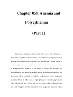
sectioning situations. Figure 2 illustrates a typical abrasive cutting machine.
Consumable-Abrasive Cutting
Abrasive cutting is the sectioning of material using a relatively thin
rotating disk composed of abrasive particles supported by a suitable
medium. The thousands of particles contacting the material in rapid
succession and at very high speeds section the material.
Consumable-wheel abrasive cutting is often performed using a
coolant, ensuring an almost plane surface without serious mechanical
or thermal damage. In selecting a wheel for a particular application,
the abrasive, bonding material, bond hardness, and density must be
considered. Coolant, wheel speed, applied pressure, and wheel edge
wear affect the quality of the cut. Table 1 lists problems and solutions
of abrasive cutoff sectioning.
Table 1 Solutions for problems encountered in abrasive cutoff sectioning
Problem Possible cause Solution
Burning (bluish
discoloration)
Overheated specimen Increase coolant rate; lessen cutting pressure; choose
softer wheel.
Rapid wheel wear Wheel bond breaking down too rapidly Choose harder wheel; lessen cutting pressure.
Frequent wheel breakage Uneven coolant distribution, loose specimen
fixturing
Distribute coolant uniformly; fix specimen rigidly.
Resistance to cutting Slow wheel breakdown Choose softer wheel; reduce coolant flow; use oscillating
stroke.
Cutter stalls Cutter too light for the work Use heavier cutter; limit sample size.
Source: Ref 2
Wheel Selection. Abrasive wheels afford more control over the conditions used than do other types of specimen
sectioning. Many factors determine the suitability of a particular wheel when cutting a given material:
• The nature of the abrasive
• The size of the abrasive grains
• The nature of the bond
• The hardness of the bond
• The porosity of the wheel
Silicon carbide is preferred for cutting non-ferrous metals and nonmetals. Alumina (Al
2
O
3
) is recommended for ferrous
metals. Coarse-grain wheels generally cut heavier sections faster and cooler, but fine-grain wheels produce smoother cuts
with less burring. Fine-grain wheels are therefore recommended for cutting delicate materials, such as thin-wall tubing.
Cutoff wheels with grit sizes from 60 to 120 are recommended for sectioning metallographic specimens. The surface
finish does not require coarse grinding, and the grinding sequence usually can begin with a 180-grit silicon carbide.
Fig. 2 Typical abrasive cutter. (Buehler Ltd.)
Resin-bonded wheels, which have very high cutting rates, are generally used for dry cutting and find application in plant
production cutting. Wet cutting wheels require a rubber or rubber-resin bond and are used in metallographic laboratories.
The rate of wheel deterioration depends on the type of bond used. Resin- and resinoid-bonded wheels generally break
down more rapidly than rubber-bonded wheels. The rubber bond retains abrasive particles more tenaciously, resulting in
slower wheel wear and more cuts per wheel. In addition, the rubber forms a solid bond; that is, there are no pores.
However, resin used as a bond sets up in a polymerization process and there are extremely small pores throughout the
wheel that may or may not be near abrasive grains. Therefore, resin-bonded wheels wear away faster, but always present
a fresh cutting surface, because each abrasive grain is ejected before it becomes dull. The abrasive used is more important
than the bond. Selection of bond is usually based on objections to the odor of burning rubber as the wheel degrades.
Two terms used in selecting abrasive cutoff wheels are "hard" and "soft." These terms do not refer to the hardness of the
abrasive grains but to how the wheel breaks down. Silicon carbide (approximately 9.4 on the Mohs scale) and Al
2
O
3
(approximately 9.0) differ only slightly in hardness. A hard wheel (one made with hard bonding material) is usually best
for cutting soft stock, but a soft wheel is preferred for cutting hard materials. A good general-purpose cutoff wheel is a
medium-hard silicon carbide abrasive wheel.
In rubber-resin wheels, the amount of bonding material and the percentage of free space determine the hardness or wheel
grade. A more porous, less dense (softer) wheel breaks down faster because the abrasive particles are held more loosely.
Softer wheel's are used because fresh, sharp abrasive grains are more frequently exposed. Less porous, more dense wheels
are harder, break down slower, and are better for softer materials.
Coolants. Water alone should not be used as a coolant for wet sectioning. A coolant should contain a water-soluble oil
with a rust-inhibitor additive, which protects the moving parts of the cutoff machine, minimizes the possibility of burning,
and produces better cuts. Some foaming of the coolant is desirable.
The preferred cooling condition is submerged sectioning, in which the entire piece is under water. Submerged sectioning
is recommended for heat-sensitive materials that undergo microstructural changes at low temperatures. For example, as-
quenched alloy steels with an untempered martensitic microstructure can readily transform to tempered martensite with
the frictional heat developed. The quality of a submerged cut is excellent, and the specimens produced will not require
extensive grinding. Section size, material, and hardness dictate whether submerged cutting can be employed. Submerged
cutting will tend to make a wheel bond act harder.
Wheel speed must be carefully considered in the design of a cutter and the selection of wheels for a given cutter. In the
interest of safety, maximum operating speeds printed on the specific blade or wheel should never be exceeded. Also,
increased wheel speed may introduce frictional heat, which damages the microstructure.
Wheel edge wear may be used to determine whether the correct wheel has been selected. Abrasive wheels that show
little or no wear are not performing satisfactorily. Controlled wheel loss indicates that the wheel bond is breaking down,
exposing fresh abrasive grains for faster, more effective, and cooler cutting. Wheels that do not deteriorate fast enough
may become glazed with specimen material, resulting in poor cutting and excessive specimen heating. Exerting additional
pressure will most likely cause over-heating.
The acceptable rate of wheel loss is:
M
LR
W
=
where LR is wheel life ratio, M is area of material cut, and W is area of abrasive wheel consumed. In plant production
cutting, resin-bonded wheels are commonly used without a coolant. Rate of cutting is the main concern, because this step
probably precedes any heat treating. In this application, an M/W ratio of 1.5:1 is acceptable. In other words, 1.5 times
more material should be cut as wheel area consumed.
Shelf Life. Rubber-bonded wheels have a definite shelf life, which ranges from 12 to 18 months, depending on storage
and climatic conditions. The rubber has a tendency to harden and become brittle. Storing abrasive wheels in an extremely
warm area hastens the degradation of the rubber, further reducing shelf life. Abrasive wheels should be removed from
their shipping containers and laid flat on a rigid surface in a relatively dry environment; they should never be hung on a
wall or stored on edge, because warpage can occur. Resin-bonded wheels should be stored in the same manner as rubber-
bonded wheels; a dry atmosphere is particularly important. Storage in a high-humidity area can lead to early
disintegration of the resin bond, because resin can absorb moisture, which eventually weakens the bond.
Surface Damage. Abrasive-wheel sectioning can produce damage to a depth of 1 mm (0.04 in.). However, control of
cutting speed, wheel pressure, and coolant application minimizes damage.
Nonconsumable Abrasive Cutting
The exceptional hardness and resistance to fracturing of diamond make it an ideal choice as an abrasive for cutting.
Because of its high cost, however, diamond must be used in nonconsumable wheels. Diamond bort (imperfectly
crystallized diamond material unsuitable for gems) that has been crushed, graded, chemically cleaned, and properly sized
is attached to a metal wheel using resin, vitreous, or metal bonding in a rimlock or a continuous-rim configuration.
Metal-bonded rimlock wheels consist of metal disks with hundreds of small notches uniformly cut into the
periphery. Each notch contains many diamond particles, which are held in place with a metal bond. The sides of the wheel
rim are serrated and are considerably thicker than the core itself, a construction that does not lend itself to delicate cutting.
When cutting more ductile materials, the blades will require more frequent dressing.
Rimlock blades are recommended for the bulk cutting of rocks and ceramics where considerable material loss may be
tolerated. Kerosene or mineral spirits are used as the coolant/lubricant, and a constant cutting pressure or feed must be
maintained to avoid damaging the rim.
Continuous-rim resin-bonded wheels consist of diamond particles attached by resin bonding to the rim of a metal
core. These blades are suitable for cutting very hard metallics, such as tungsten carbide, and nonmetals, such as high-
alumina ceramics, dense-fired refractories, and metal-ceramic composites. Water-base coolants are used.
Wafering Blades. For precision cutting of metallographic specimens or thin-foil specimens for transmission electron
microscopy, very thin, small-diameter wafering blades are used. These blades are usually constructed of diamond, metal
powders, and fillers that are pressed, sintered, and bonded to a metal core. Wafering blades are available in high and low
diamond concentrations. Lower concentrations are better for harder materials, particularly the nonmetals; higher
concentrations are preferred for softer materials.
Wafering blades may be used with diamond saws. Unlike some other methods of sectioning, the diamond saw uses
relatively low speeds (300 rpm maximum) and a thin, continuous-rim diamond-impregnated blade to accomplish true
cutting of nearly all solid materials. Applications include cutting of hard and soft materials, brittle and ductile metals,
composites, cermets, laminates, miniature devices, and honeycombs. The as-cut surface is generally free of damage and
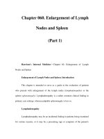
distortion and is ready for microscopic examination with minimum polishing or other preparation. Figure 3 illustrates a
typical low-speed diamond saw.
Fig. 3 Typical low-speed diamond saw. (Leco Corp.)
Wire Saws (Ref 3)
The need to produce damage-free, single-crystal semiconductor surfaces for the electronics industry has generated interest
in using the wire saw in the metallographic laboratory. Applications include:
• Removing samples from the bulk material
• Cutting electronic assemblies for failure analysis
• Cutting thin-wall tubing
• Cutting fiber-reinforced and laminated composite materials
• Cutting honeycomb structural materials (Fig. 4, 5)
• Cutting polymers (Fig. 6)
• Cutting metallic glasses (Fig. 7)
• Preparing thin specimens for transmission electron microscopy, electron probe micro-
analysis, ion
probe analysis, and x-ray diffraction analysis
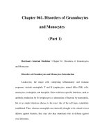
Fig. 4 Three pieces of honeycomb cut with a diamond wire saw
. Note the absence of burrs and breakout. From
left: titanium; section from helicopter rotor blade consisting of plastic, paper honeycomb, epoxy, stainless steel
screws, and Kevlar; extruded ceramic honeycomb used in automotive catalytic converters. (Laser
Technology,
Inc.)
Fig. 5 Kevlar honeycomb cut with a wire saw. (Laser Technology, Inc.)
Fig. 6
Woven Kevlar cut with a wire saw. This material is used in bulletproof vests. When woven into thick
pieces, it is used in tanks and is comparable to armor steel plate of equal thickness. (Laser Technology, Inc.)
Fig. 7 Amorphous iron (Metglas) cut with a wire saw. Each laminate is 0.1 mm (0.004 in.) thick.
(Laser
Technology, Inc.)
In principle, a fine wire is continuously drawn over the sample at a controlled force. Cutting is accomplished using an
abrasive slurry applied to the wire, a chemical solution (generally acidic) dripped onto the wire, or electrolytic action.
Although cutting rates are much lower than those of abrasive cutoff wheels, hacksaws, or band saws, the deformation
produced is negligible, and subsequent grinding and polishing is often not necessary.
Wire saws are available in a variety of designs. Some move the specimen into the wire, some move the wire into the
specimen, some run horizontal, and some run vertical. A saw in which the wire runs vertical is advantageous if a
specimen is to be removed from bulk material. In this case, the material is attached to an x-y table and is moved into the
saw.
Various methods have been devised for drawing the wire across the specimen. The endless-wire saw consists of a loop of
wire fastened together at its ends and driven in one direction (Fig. 8). The oscillating wire saw passes a wire back and
forth across the sample, usually with a short stroke. A variation of this technique employs a 30-m (100-ft) length of wire
that is fed from a capstan across the workpiece and back onto the capstan. The direction of the capstan is reversed at the
end of each stroke. The capstan is further shuttled back and forth to maintain the alignment of the wire regarding the
pulleys.
Abrasives. Any crystalline material can be
used as an abrasive in wire sawing if the
abrasive is harder than the specimen to be cut.
Although natural abrasives, such as emery
and garnet, have been used extensively, the
best overall abrasive currently available is
synthetic diamond. There are two methods for
applying abrasives to the wire. Loose abrasive
can be mixed with a liquid vehicle as a slurry
to be applied at the kerf behind the wire, or
the abrasive can be bonded to a stainless steel
wire core.
In the first method, part of the abrasive
remains with the specimen and erodes the wire. Furthermore, much of the abrasive is wasted, which precludes using
diamond in a slurry. In the second method, all the abrasive moves with the wire to cut the specimen. Therefore, only a
fixed quantity of abrasive is employed; diamond then becomes economically feasible. Figure 9 illustrates typical
diamond-impregnated wires.
Fig. 8 Wire saw with an endless loop. (South Bay Technology, Inc.)
Lubricants. Water is used in wire sawing with diamond-
impregnated wire. This is not used to lubricate the cut, nor
is it used to prevent heat buildup. The amount of heat
generated is negligible, and lubrication of the wire is
unnecessary. Water is used to wash out the debris that
would accumulate above the wire and prevent the easy exit
of the wire when the cut is complete.
Force. As force is increased between the wire and the
specimen, the bow in the wire increases, even though the
wire is under maximum tension. Little is gained in cutting
time by increasing the force. When the force is increased
excessively, the bow becomes so great that the wire has a
tendency to wander, which increases the kerf. When
wandering occurs, more material is being cut away, and
cutting time increases. This also shortens wire life.
Therefore, high force with the resulting wider kerf is a poor
alternative to lighter force with a straighter wire and a more
accurate cut. Lighter force also yields a better finish. If the
cut is to be flat at the bottom, the saw should be allowed to
dwell for a short time with no force.
The force between the wire and the specimen ranges from
10 to 500 gf. As an example, for a specimen that is in
limited supply, fragile, high priced, and/or delicate, a 0.08-
mm (0.003-in.) diam wire impregnated with 8-μm diamonds
would be selected. The force between the wire and the
crystal would range from 10 to 35 gf. The tension on the
wire would be 500 to 750 gf, and the wire would travel 20
to 30 m/min (60 to 100 ft/min).
When a firm, hard, tough specimen is to be cut and when
surface damage poses little or no problem, the fastest and
most economical method of cutting usually is best. For
example, a 0.4-mm (0.015-in.) diam wire impregnated with
60-μm diamonds would be chosen. The tension on the wire
would be approximately 6000 to 8000 gf. The machine
would operate at 60 m/min (200 ft/min). The force between
the wire and the specimen would range from 200 to 500 gf.
Electric Discharge Machining (Ref 4)
Electric discharge machining (EDM), or spark machining, is
a process that uses sparks in a controlled manner to remove
material from a conducting workpiece in a dielectric fluid
(usually kerosene or transformer oil). A spark gap is
generated between the tool and the sample, and the material
is removed from the sample in the form of microscopic
craters. The material produced by the disintegration of the tool and workpiece as well as by the decomposition of the
dielectric is called "swarf." Sparking is done while the sample and tool are immersed in the dielectric.
The dielectric must be kept clean to achieve the full accuracy capability of the instrument, and this is routinely
accomplished by using a pump and filter attachment. Depending on the polarity of discharge, type of generator, and
particularly the relative hardness of the sample and tool, material can be removed effectively and accurately. No contact is
required between the tool and workpiece.
Wire size Kerf size
mm
in.
Diamond
size, μm
mm
in.
0.08
0.003
8 0.08
0.00325
0.13
0.005
20 0.14
0.0055
0.2 0.008
45 0.23
0.009
0.25
0.010
60 0.29
0.0115
0.3 0.012
60 0.34
0.0135
Fig. 9 Diamond-impregnated wires
The initial preparation of metallographic specimens for optical and transmission electron microscopy can be performed on
EDM machines. Resulting samples have a surface finish of 0.13 μm (5 μin.), exhibit excellent edge definition, and can be
less than 0.13-mm (0.005-in.) thick. A typical EDM setup is shown in Fig. 10.
Depth of Damage. Electric discharge machining will
damage the specimen to several millimeters or more in depth
if precautions are not taken. Two criteria for assessing depth
of damage are, first, depth of detectable damage, which is
the depth at which the structure is altered as measured by the
most sensitive process available, and, second, the depth of
significant damage, which is the depth to which damage can
be tolerated for the application intended.
Four zones can be defined in the spark-affected surface
layer. The most strongly affected layer is the melted zone,
which can extend from fractions of a micron to hundreds of
microns, depending on the instrumentation used. In electric
discharge machining, sparks melt a shallow crater of metal
in the melted zone. Most of this is ejected at the end of the
spark. Some residual liquid material remains and freezes
epitaxially onto the solid below, leaving the melted layer in
tension and the layer beneath in compression. Deep melted
layers can cause cracking.
The second layer is the chemically affected zone, in which
the chemical composition has changed perhaps because of
reaction with the dielectric and the tool and diffusion of
impurities. This zone is generally very small due to the time
involved. The third layer is the microstrained zone, which is
subjected to large compressive forces during the heating
cycle and later during the shrinkage of the rapidly frozen
molten layer. This zone can be detected by optical
microscopy and is characterized by the presence of twins,
slip, phase changes, and, sometimes, microcracks. The
fourth layer is the submicrostrained zone. Damage in this
layer can be detected only by counting dislocations. Slip, twinning, or cracking does not occur.
Mounting of Specimens
Introduction
MOUNTING is often necessary in the preparation of specimens for metallographic study. Although bulk samples may not
require mounting, small or oddly shaped specimens should be mounted to facilitate handling during preparation and
examination. Sharp edges and corners are eliminated, increasing safety for the metallographer and avoiding damage to the
papers and cloths used in preparation. Some automatic preparation devices require mounted specimens of a specific size
and shape. Proper mounting of specimens also aids edge retention when such features as surface coatings are to be
examined. In addition, uniformly sized and shaped specimens are convenient to prepare, view, and store.
Standard mounts usually measure 25 mm (1 in.), 32 mm (1.25 in.), or 38 mm (1.5 in.) in diameter; mount thickness is
often approximately one half the mount diameter. Thickness is important in proper metallographic preparation, because
thin mounts are difficult to handle, and very thick mounts are difficult to hold flat during grinding and polishing.
Mount size and shape are sometimes influenced by the size and shape of the specimen to be mounted as well as by the
type of metallographic examination to be performed. For example, square or rectangular mounts are often used in x-ray
diffraction examination, which requires a relatively large surface. Mounting of wire, tubing, sheet, and powder specimens
requires special techniques that will be discussed below.
Fig. 10 Typical setup for electric discharge machining
Cleaning
Prior to mounting, it is often necessary to clean specimens. Cleaning may also be indicated before plating for edge
retention. With certain samples, such as those in which surface oxide layers are to be examined, cleaning must be limited
to very simple treatments, or the detail to be examined may be lost.
A distinction can be made between physically and chemically clean surfaces. Physical cleanliness implies freedom from
solid dirt, grease, or other debris; chemical cleanliness, freedom from any contaminant. In metallographic work, physical
cleanliness is usually adequate and nearly always necessary.
Vapor degreasing is frequently used to remove oil and grease left on metal surfaces from machining operations, but
ultrasonic cleaning is usually the most effective method for routine use. Specimens that require cleaning may be placed
directly in the tank of the ultrasonic cleaner, but the cleaning solution must be changed frequently. This can be avoided by
placing approximately 1 in. of water in the tank, then placing inside the tank a beaker containing the cleaning solution and
the specimen. Cleaning times are usually 2 to 5 min, but very soft specimens can be damaged by the cavitation; therefore,
ultrasonic cleaning should be limited to 30 s or less for these materials (Ref 1).
Selection of Mounting Materials
The first concern in selecting a mounting material and technique must be the protection and preservation of the specimen.
Fragile or delicate specimens are subject to physical damage. The heat and pressure required for some mounting materials
can alter microstructures. Shrinkage stresses can be high enough to pull a protective plating from the specimen, thus
limiting edge retention.
Moreover, the mount must have sufficient hardness, although hardness is not always an indication of abrasion
characteristics. Grinding and polishing characteristics should ideally be similar to those of the specimen. The mount must
also resist physical distortion caused by the heat generated during grinding and polishing as well as withstand exposure to
lubricants, solvents, and etchants.
The mounting material should be able to penetrate small pores, crevices, and other surface irregularities in the specimen.
For some types of metallographic examination, such as scanning electron microscopy, and for electrolytic polishing, an
electrically conductive mount is desirable.
The mounting medium should be simple and fast to use and convenient to store. It should not be prone to formation of
defects in the cured mount, such as cracks or voids. Transparent mounts are often advantageous. The mount material
should present no health hazards, and it should be readily available at a reasonable cost.
Because one mounting material or technique cannot fulfill every requirement, a variety of materials and methods are
available. Proper selection will yield a mount that meets the most critical requirements.
Mechanical Mounting Devices
Mechanical clamping devices facilitate mounting and can be very effective, particularly in preparing transverse or
longitudinal sheet surfaces. Clamps for this type of work are usually fabricated from approximately 6-mm (0.25-in.) thick
plate stock, which can be cut into blocks of various sizes. A common size is approximately 12 mm by 38 mm (0.5 in. by
1.5 in.). Holes are drilled into each end of the clamp halves, and one half is threaded to receive a bolt of suitable length.
Mating holes in the other half are drilled just large enough to clear the bolt threads. Specimens are then cut or sheared to a
length that will fit between the bolts and sandwiched between the clamp halves. The clamp is placed in a vise, and the
clamp bolts are tightened.
The pressure used to hold the specimens within a mechanical clamp can be important. Insufficient pressure can result in
seepage and abrasive entrapment. Too much pressure could damage the specimens.
Spacers, often used with this type of mechanical mount, especially if specimen surfaces are rough, are thin sheets of such
materials as copper, lead, or plastic. Specimens can also be coated with a layer of epoxy or lacquer before being placed in
the clamp. For maximum edge retention, a spacer should have abrasion and polishing rates similar to those of the
specimen. Material for the spacer and the clamp should be selected to avoid galvanic effects that would inhibit etching of
the specimen. If the etchant more readily attacks the clamp or spacer, the specimen will not etch properly.
Another common mechanical mount is a cylinder or other convenient shape in which the specimen is held by a set screw.
Again, abrasion and polishing rates should approximate those of the specimen, and the mount should be inert to any
solvents and etchants used or have the same reactivity as the specimen. Figure 1 illustrates three mechanical mounting
devices.
Fig. 1 Typical examples of clamps used for mechanical mounting. (Ref 2)
Plastic Mounting Materials
The various plastics used for metallographic mounting can be classified in several different ways, according to the
technique used and the properties of the material. Plastics may be divided into one group that requires the application of
heat and pressure and another group that is castable at room temperature. The former group is usually obtained as
powders; the latter group, which requires blending of two components, may be obtained as two liquids or as a liquid and a
solid.
Plastics that require heat and pressure for curing are known as compression-mounting materials. These can be further
divided into thermosetting resins and thermoplastic resins.
Thermosetting resins require heat and pressure during molding, but can be ejected from the mold at the molding
temperature. The two most widely used thermosetting resins are Bakelite and diallyl phthalate. Melamine, although rather
brittle when used alone, and the recently developed compression-mounting epoxies have also been used.
Bakelite, popular because of its low cost and convenience, is available as red, green, or black powders or as "premolds,"
which are already formed to standard mount sizes. Premolds can be used if the specimen is a uniform shape and if the
initial application of pressure will not damage the specimen. Bakelite normally contains wood flour fillers but is also
available as 100% resin (Bakelite amber).
Depending on mold diameter, curing times for Bakelite vary from 5 to 9 min at 29 MPa (4200 psi) and 150 °C (300 °F).
Curing times for premolds range from 3 to 7 min at the same pressure and temperature. Bakelite, however, exhibits
relatively low hardness, limited abrasion resistance, significant linear shrinkage upon cooling, and limited edge
protection. Typical properties of Bakelite and diallyl phthalate are given in Table 1.
Table 1 Typical properties of thermosetting molding resins
Molding conditions
Temperature
Pressure
Heat
distortion
temperature
Resin
°C °F MPa
psi
Time,
min
°C °F
Coefficient
of
thermal
expansion
in./in. °C
(a)
Abrasion
rate,
μm/min
(b)
Polishing
rate,
μm/min
(c)
Transparency
Chemical
resistance
Bakelite
(wood-
filled)
135-
170
275-
340
17-
29
2500-
4200
5-12 140 285 3.0-4.5 ×
10
-5
100 2.9 Opaque Attacked
by strong
acids and
alkalies
Diallyl
phthalate
(asbestos-
filled)
140-
160
285-
320
17-
21
2500-
3000
6-12 150 300 3.5 × 10
-5
190 0.8 Opaque Attacked
by strong
acids and
alkalies
Source: Ref 1
(a)
Determined by method ASTM D 648.
(b)
Specimen 100 mm
2
(0.15 in.
2
) in area abraded on slightly worn 600-grit silicon carbide under load of 100 g at rubbing speed of 10
5
mm/min (4 ×
10
3
in./min).
(c)
25-mm (1-in.) diam mount on a wheel rotating at 250 rpm covered with synthetic suede cloth and charged with 4 to 8 μm diamond paste.
Diallyl phthalate is available as a powder with mineral or glass filler. In glass-filled form, it will provide harder mounts
and better edge retention than Bakelite. Although mineral-filled diallyl phthalate does not have specific edge retention
properties, it and glass-filled diallyl phthalate exhibit good resistance to chemical attack, which is useful when using
powerful etchants or etching at elevated temperatures. Depending on mold diameter, curing times for diallyl phthalate
vary from 7 to 12 min at approximately 22 MPa (3200 psi) and 150 °C (300 °F). Copper-or aluminum-filled diallyl
phthalate can be used as a conductive mount for electrolytic polishing or scanning electron microscopy.
Compression-mounting epoxies provide low shrinkage and produce excellent edge retention. Molding time, pressure, and
temperature are similar to those used for diallyl phthalate, but molding defects are less common. A mold release agent is
generally required to prevent the mount from adhering to the ram.
Thermoplastic resins also require heat and pressure during molding, but must be cooled to ambient temperature under
pressure. These materials can be used with delicate specimens, because the required molding pressure can be applied after
the resin is molten. Transparent methyl methacrylate (Lucite or Transoptic), polystyrene, polyvinyl chloride (PVC), and
polyvinyl formal are some of the thermoplastic resins. Properties are listed in Table 2.
Table 2 Typical properties of thermoplastic molding resins
Molding conditions
Heating Cooling
Temperature
Pressure Temperature
Pressure
Heat
distortion
temperature
(a)
Resin
°C °F MPa
psi
Time
(min)
°C °F MPa
psi
Time
(min)
Transparency
°C °F
Coefficient
of thermal
expansion,
in./in. °C
Abrasion
rate,
μm/min
(b)
Polishing
rate,
μm/min
(c)
Chemical
resistance
Methyl
methacrylate
140-
165
285-
330
17-
29
2500-
4200
6 75-
85
165-
185
max max 6-7 Water, white to
clear
65 150 5-9 × 10
-5
. . . 7.5 Not resistant to
strong acids
and some
solvents,
especially
ethanol
Polystyrene 140-
165
285-
330
17 2500 5 85 185-
212
max . . . 6 . . . 65 150 . . . . . . . . . . . .
Polyvinyl
formal
220 430 27 4000 . . . . . . . . . . . . . . . . . . Light brown,
clear
75 165 6-8 × 18
-5
20 1.1 Not resistant to
strong acids
Polyvinyl
chloride
120-
160
250-
320
0.7 100 nil 60 140 27 4000
. . . Opaque 60 140 5-18 × 10
-5
45 1.3 Resistant to
most acids and
alkalies
Source: Ref 1