Volume 09 - Metallography and Microstructures Part 8 ppsx
Bạn đang xem bản rút gọn của tài liệu. Xem và tải ngay bản đầy đủ của tài liệu tại đây (5.77 MB, 100 trang )
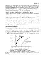
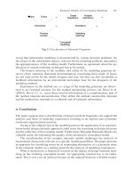
Fig. 123 Haynes 21 casting aged 24 h at 870 °C (1600 °F). M
7
C
3
particles and precipitated M
23
C
6
at grain
boundaries and in grains of fcc matrix. See also Fig. 124. Electrolytic etch: HCl. 500×
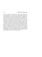
Fig. 124 Replica electron micrograph of Fig. 123. Massive primary M
7
C
3
particle and secondary precipitate of
M
23
C
6
at grain boundaries and within grains. Electrolytic etch: HCl. 3000×
Fig. 125 Haynes 31, as-cast. Structure consists of large, primary M
7
C
3
particles and grain-boundary M
23
C
6
in an
α (fcc) matrix. See also Fig. 126 and 127. Electrolytic etch: 2% CrO
3
. 400×
Fig. 126 Haynes 31, as-cast thin section, aged 22 h at 730 °C (1350 °F). Precipitated M
23
C
6
at grain
boundaries and adjacent to primary carbide (M
7
C
3
) particles. Electrolytic etch: 2% CrO
3
. 400×
Fig. 127 Haynes 31, as-cast thick section, aged 22 h at 730 °C (1350 °F). Large particles are M
7
C
3
; grain-
boundary and mottled dispersions are M
23
C
6
; fcc matrix. Electrolytic etch: 2% CrO
3
. 500×
Fig. 128 Haynes 151, as-cast. Structure consists of dispersed islands of large primary carbide (M
6
C) in the α
(fcc) matrix. See also Fig. 129. Electrolytic etch: HCl and CrO
3
. 200×
Fig. 129 Same as Fig. 128, but at higher magnification, which reveals details of the M
6
C (note the lamellar
form) in the α (fcc) matrix. Electrolytic etch: HCl and CrO
3
. 500×
Fig. 130 Haynes 151 casting aged 16 h at 760 °C (1400 °F) M
6
C particles and precipitated M
23
C
6
at grain
boundaries and next to M
6
C particles in the fcc matrix. Electrolytic etch: HCl and CrO
3
. 500×
Fig. 131
Fig. 132
Fig. 133
98M2 Stellite, as-investment-cast ring. Microstructure consists of large primary carbides in a matrix of
secondary carbides and cobalt-chromium-tungsten solid solution. Some primary carbides have
solidified in a star-like array. Electrolytic etch: 50% HNO
3
. Fig. 131: 100×; Fig. 132: 500×; Fig. 133:
1000×. (S.E. Wall and R.L. Snyder)
Fig. 134
Fig. 135
Fig. 136
98M2 Stellite, as-investment-cast bar. Very large primary carbides in a matrix of smaller secondary
carbides and cobalt-chromium-tungsten solid solution. Electrolytic etch: 50% HNO
3
. Fig. 134: 100×
Fig. 135: 500×; Fig. 136: 1000×. (S.E. Wall and R.L. Snyder)
Fig. 137 WI-52, as-cast. The solid gray islands are complex chromium-
tungsten carbide; particulated islands
are niobium carbide. The dark dots are silicate inclusions in the matrix of cobalt-chromiu
m solid solution.
Electrolytic etch: 5% H
3
PO
4
. 500×
Fig. 138 MAR-M 302, as-cast. Structure consists of primary, or eutectic, M
6
C particles (dark gray) and MC
particles (small white crystals) in the matrix of cobalt-chromium-tungsten solid solution. See Fig. 139
for better
resolution of constituents. Kalling's reagent. 100×
Fig. 139 MAR-M 302, as-cast, at a higher magnification than Fig. 138
. The mottled gray islands are primary
eutectic carbide; the light crystals are MC particles; the peppery constituent within grains of the matrix is M
23
C
6
.
Kalling's reagent. 500×
Fig. 140 MAR-M 509, as-cast. The structure consists of MC particles in script form and M
23
C
6
particles in
eutectic form (gray areas) and precipitate form in the dendritic α solid-solution matrix (fcc).
Kalling's reagent.
100×
Fig. 141 Same as Fig. 140, but at a higher magnificatio
n to reveal morphology of MC script particles, primary
eutectic particles (M
23
C
6
), and precipitated M
23
C
6
(shadowy constituent) in the α (fcc) matrix.
Electrolytic etch:
5% H
3
PO
4
. 500×
Fig. 142 MAR-M 509, aged at 705 °C (1300 °F), Thin-foil electron micrograph
. Top left to bottom right:
precipitated M
23
C
6
; α(fcc) matrix; blocky M
23
C
6
with cobalt; cobalt with internal precipitate; lamellar M
23
C
6
in
matrix. As-polished. 10,000×
Aluminum Alloys: Metallographic Techniques and Microstructures
Revised by Richard H. Stevens, Aluminum Company of America
Introduction
ALUMINUM ALLOYS encompass a wide range of chemical compositions and thus a wide range of hardnesses.
Therefore, the techniques required for metallographic preparation and examination vary considerably. Softer alloys
generally are more difficult to prepare by mechanical polishing, because (1) deformation caused by cutting and grinding
extends to a greater depth, (2) the embedding of abrasive particles in the metal during polishing is more likely, and (3)
relief between the matrix and second-phase particles, which are considerably harder than the matrix, develops more
readily during polishing. Harder alloys, although easier to prepare, present a greater variety of phases and complexities of
structure. However, methods exist for circumventing the difficulties of preparing and examining soft and hard alloys.
Many methods are general and apply to all metals, but some have been developed specifically for aluminum alloys.
Many recovery and precipitation processes in aluminum alloys can occur at relatively low temperatures, such as 150 to
250 °C (300 to 480 °F), which are readily produced in such operations as cutting, grinding, and mounting. These
operations rarely produce changes visible by optical microscopy, although they may do so in extreme cases. However,
they can produce changes in structure that are visible with an electron microscope. The metal must not overheat during
specimen preparation: extra care must be taken when using unconventional methods or materials.
Aluminum is a chemically active metal that derives its stability and corrosion resistance from a protective film of oxide
that prevents as-polished and etched surfaces from deteriorating rapidly. Oxide films thicker than normal can be formed
in a controlled manner by making the specimen the anode of an electrolytic cell. These films can be used to reveal
microstructural features.
When some types of anodic films are formed on a polished surface and when the surface is examined with reflected
plane-polarized light passed through an analyzer, striking contrast effects are produced that reveal grain size and shape
and orientation differences (Ref 1). Anodic film replicas have also proved useful in electron microscopy.
Reference
1.
P. Lacombe and M. Mouflard, "Les Applications de la Micrograph
ie en Couleurs par Formation des
Pellicules Minces Epitaxiques à Teintes d'interference à l'Ètude de l'Aluminium, du fer et du Cuivre,"
Editions Mètaux Saint Germain en Laye; extract from Mètaux (Corrosion Ind.),
Vol 28 (No. 340), Dec 1953,
p 471-488
Preparation for Macroscopic Examination
Aluminum alloys require the same principles of preparation for macroscopic examination as most metals. Careful and
thorough visual inspection of the part or shape to be examined should precede cutting or etching. Fracture surfaces should
be carefully preserved to guard against abrasion or contamination. If the part is to be sectioned, selection of the cutting
plane is determined by directionality or fibering due to the working process by which the part was formed, by the
suspected or known form of defect, and by the general form or nature of the part (for example, casting, forging, extrusion,
or weldment).
Mechanical Preparation. The purpose of the examination and the type of etchant to be used determine the proper
preparation of a cut surface for etching. Most macroetchants can reveal some details of macrostructure on a rough cut
surface, but the overetching necessitated by the lack of initial smoothness can easily obscure significant details.
Generally, a smoother or more highly polished surface requires less etching to reveal the same amount of gross detail; it
also reduces the chance of losing fine detail.
Machined surfaces frequently are acceptable for macroetching and examination. However, machining with a dull tool or
at unfavorable speed and feed can distort the surface and misrepresent grain structure or degree of porosity. This is
particularly important when using dye penetrant and developer for revealing density, shrinkage, or gas porosity in a cast
material. A shaper or milling machine is preferred to a lathe, which does not provide a constant cutting speed on a flat
surface.
Chemical Preparation. Removal of cutting oils and other greasy contaminants from aluminum surfaces before etching
is helpful, but not always necessary. Table 1 lists several etchants and etching methods that will adequately prepare
specimens for macroexamination. Other combinations of concentration, proportions or dilution, temperature, and time
often can be used without greatly altering the end effects.
Table 1 Etchants for macroscopic examination of aluminum alloys
See Table 2 for applicability to specific alloys
Etchant Composition Procedure for use
1
(caustic
etch)
10 g NaOH to each 90 mL H
2
O Immerse specimen 5-15 min in solution heated to 60-70 °C (140-160 °F)
(a)
,
rinse in water, dip in 50% HNO
3
solution to desmut, rinse in water, dry.
2
(Tucker's
reagent)
45 mL HCl (conc), 15 mL HNO
3
(conc), 15 mL HF (48%), 25 mL
H
2
O
Mix fresh before using. Immerse or swab specimen for 10-15 s, rinse in warm
water, dry, and examine for desired effect. Repeat until desired effect is
obtained.
3
1 mL HF (48%), 9 mL H
2
O Requires fairly smooth surface. Immerse until desired effect is obtained, hot
water rinse, dry.
4
(Poulton's
reagent)
12 mL HCl (conc), 6 mL HNO
3
(conc), 1 mL HF (48%), 1 mL H
2
O
May be premixed and stored
(b)
for long periods. Etch by brief immersion or by
swabbing. Rinse in cool water, and do not allow the etchant or the specimen to
heat during etching.
5
50 mL HCl (conc), 15 mL HNO
3
(conc), 3 mL HF (48%), 5 mL
FeCl
3
solution (conc)
Mix fresh before using. Cool solution to 10-15 °C (50-60 °F) with jacket of
cold water. Immerse a few seconds, rinse in cold water; repeat until desired
effect is obtained.
6
10 mL HCl (conc), 30 mL HNO
3
(conc), 20 mL H
2
O, 5 g FeCl
3
Mix fresh before using. Add HCl last. Use at room temperature. Immerse a few
seconds, rinse in cold water; repeat until desired effect is obtained. Can also use
by swabbing.
7
60 mL HCl (conc), 40 mL HNO
3
(conc)
Mix fresh before using. Immerse or swab for a few seconds, rinse in cold water,
dry, examine. Repeat until desired effect is obtained.
8
20 g CuCl
2
(cupric chloride), 100
mL H
2
O
Immerse specimen for a few seconds. Remove copper deposit with a mixture of
6 parts HNO
3
(conc) and 1 part HF (conc). Repeat until desired effect is
obtained, cleaning with HNO
3
-HF mixture and rinsing in water between steps.
(a)
This etchant may be used without being heated, but etching action will be slower.
(b)
Solution should be stored in a vented container, preferably under a fume hood, to prevent buildup of gas pressure. The container should be
made of polyethylene or be lined with wax.
The caustic etch (etchant 1 in Table 1) is an excellent degreaser. The acidic etchants are more likely than the caustic etch
to act unevenly if the surface is not precleaned. Thorough degreasing should precede dye penetrant testing. Before the dye
penetrant is applied, a very light caustic etch (etchant 1 in Table 1) can be used to remove any minor sealing of porosity
by smeared metal. These precautions ensure a surface free from smeared metal and are particularly important in
evaluating direct-chill cast ingots, in which the dimensions of individual pores may be quite small.
Customary safety precautions in handling strong reagents, including proper ventilation should always be observed.
Etchant containers should be chosen for their resistance to reaction with hydrofluoric acid (HF) or caustic. Final rinsing in
warm or hot tap water facilitates drying. Blowing dry with clear compressed air lessens the chances of staining.
Preparation for Macroscopic Examination
The optimum procedure for microscopic examination is determined using the same considerations as for macroscopic
examination, although the area to be examined usually is smaller.
Sectioning. Aluminum alloys can be sectioned by any standard cutting method; however, the cutting must not alter the
structure or the configuration of the specimen in the plane to be examined. Because many aluminum alloys are soft,
sawing or shearing should be done at a distance from the plane to be polished and then the intervening deformed material
removed by wet grinding and polishing. An abrasive saw permits cutting closer to the plane of polishing.
The temperature of the metal must not increase sufficiently during cutting to affect adversely the results of the
examination. Because the grains in wrought aluminum alloys are rarely equiaxed, sections for determining grain size must
be defined regarding the principal direction of working.
Mounting in a plastic medium to form a cylindrical piece is the accepted procedure, unless the specimen is large enough
to be hand held for subsequent grinding and polishing. Standard mounting materials and methods are described in the
article "Mounting of Specimens" in this Volume.
Special problems relating to the selection of mounting method or material may be caused by (1) inclusion of alloys of
dissimilar hardnesses in the same mount, (2) the need to maintain flatness to the edge, (3) the need to mount thin sheet
specimens for polishing in a plane perpendicular to the rolled surface, and (4) the need to connect electrical leads to one
or more specimens for subsequent electropolishing or electrolytic etching. The mounting medium should not be so hard
that it inhibits polishing of the softest aluminum contained in the mount or so soft that it allows rounding of the metal
edges. Specimen edges whose flatness must be preserved should not be placed near the outer edge of the mounting ring.
Thin sheet specimens can be bent or clamped in various ways, but it is most convenient to pack mount them by bolting
layers together. The bolted pack can be mounted in plastic or cut to a convenient shape and size for polishing. If a bolt
material other than an aluminum alloy is used, it should be coated or insulated before etching to prevent galvanic
corrosion.
Entrapment and seepage of liquid between layers can be minimized by immersing the pack mount in a bath of molten wax
for a few minutes, removing it from the bath and cooling it until the wax has solidified, then wiping off the excess wax.
Interleaving with a soft aluminum foil or thin sheet helps distinguish the interface between similar alloys, aids in
revealing the thickness of anodic films, and minimizes entrapment and seepage of liquid between layers. Pack mounts are
also convenient when multiple-sheet specimens are to be electropolished or electrolytically etched.
Various methods are used for making electrical connections to metal mounted in plastic. One method is to make the
mount electrically conductive by preparing it from an approximately equal mixture of plastic mounting powder with
clean, dry aluminum chips from a band saw.
When the heat or pressure of mounting must be avoided, various castable plastics can be used at room temperature. They
can be used to fill in crevices and cracks by vacuum impregnation, even when thermal mounting is to be used.
Grinding. Aluminum alloys can be ground using the same general techniques for all metals. Because aluminum alloys
can be ground readily with various abrasives, selection is made on an individual basis. Generally, grinding is performed in
successive steps using silicon carbide abrasive papers of 180, 220, 320, 400, and 600 grit. The starting grit size depends
on the type of cut surface being removed. If the specimen has been cut with a hacksaw or band saw, 180- or 220-grit
paper should be used. If the specimen has been cut with a jeweler's saw or a fine abrasive or diamond wheel, initial
grinding can be performed using 320-, 400-, or 500-grit paper.
Silicon carbide papers in grit sizes of 800 and 1000 are available from some suppliers; these are equivalent to 10 and 5
μm, respectively. Using 800- and 1000-grit silicon carbide papers, fine grinding can be achieved without using diamond
abrasives. These finer grit sizes cause less surface deformation and produce a more uniform surface finish than diamond
abrasives, thus facilitating subsequent polishings. If these papers are used, the number of grinding steps can often be
reduced to five: 220, 400, 600, 800, then 1000 grit.
Motor-driven belt grinders or disk-shaped laps hasten grinding, but care must be taken to prevent overheating of the
specimen. Running water suffices as a coolant and lubricant at all stages when used with a water-resistant backing for
abrasive materials. The specimen should be thoroughly washed after each grinding to prevent carryover of abrasive
particles to the next stage.
Abrasive particles embed easily into softer aluminum alloys. Therefore, kerosene, with or without dissolved paraffin, may
be applied periodically to metallographic emery papers while hand grinding. During wet grindings with silicon carbide
papers, however, less pressure should be applied to the specimen and adequate water should be used to flush away loose
abrasive particles.
Mechanical Polishing
Mechanical polishing can be accomplished in two steps: rough and finish polishing.
Rough polishing is performed using a suspension of 600-grit alumina (Al
2
O
3
) powder in distilled water (50 g/500 mL
H
2
O) on a billiard cloth fixed to a rotating wheel. Diamond abrasive of 6, 3, or 1 μm (depending on the final grinding step
used) on a short-nap cloth disk can also be used. The 600-grit Al
2
O
3
is excellent for removing the thin layer of metal that
smears over fine cracks and porosity during rough grinding; however, excessive time and pressure will result in rounded
specimen edges and constituents in relief.
These problems can be addressed with a subsequent step using 1-μm diamond on a short-nap cloth. The diamond can be
applied as a paste or as spray and replenished as needed to provide continued cutting action. During diamond polishing, a
lubricant of kerosene or a propylene glycol solution should be added to the rotating wheel. Propylene glycol solutions are
the most commonly used lubricant.
Considerable hand pressure is used initially, then gradually reduced. Wheel speeds of 500 to 700 rpm are typical. For
rough polishing to be successful, polishing times should range from 1 to 2 min, and short-nap cloths should be used.
Specimens should be thoroughly washed or ultrasonically cleaned to remove all abrasive after rough polishing.
Final polishing of aluminum alloys is generally performed using a pure, heavy grade of magnesium oxide (MgO)
powder with distilled or deionized water on a uniformly textured medium- or short-nap cloth. A suspension of silicon
dioxide (SiO
2
) in distilled water is also available commercially. This medium has a slightly basic pH and a grit size of
0.04 μm. An advantage of SiO
2
is its ability to remain in suspension; therefore, it can be purchased in the liquid form,
then used without preparation.
The same guidelines for cleanliness apply to SiO
2
as to MgO; the polishing cloth must be cleaned carefully immediately
after each use to prevent the compound from hardening, thus rendering the polishing cloth ineffective. The mouth of the
container in which the suspension of SiO
2
is stored should be wiped clean before pouring any material on the polishing
cloth so that the hard particles that have formed around the mouth are not carried onto the cloth. The MgO should be kept
in tight, dry containers. It can also be reclaimed by sifting through a 200-mesh screen or by baking for a few minutes at
800 to 1000 °C (1470 to 1830 °F).
When final polishing with MgO, a teaspoon of the abrasive is applied near the center of the cloth, moistened with distilled
or deionized water, then worked into a paste. A variable-speed wheel is preferred for final polishing; however, a two-
speed wheel is satisfactory if the speeds are approximately 350 rpm or less.
Considerable hand pressure and frequent rotation of the specimen are used for the first few minutes, and only enough
water is added to avoid dryness and pulling of the specimen by the cloth. Gradually, pressure is reduced, and more water
is added to wash away excess abrasive. Toward the end of the polish, copious water can be used to remove all abrasive,
and the polishing cloth in effect wipes the specimen clean.
Residual abrasive may be removed by lightly applying a clean, wet cotton swab. Final rinsing can be done with warm or
hot tap water, and the specimen should be blown dry. The operation requires 5 to 15 min, depending on the skill of the
operator, the alloy, and prior preparation.
A similar procedure is followed when using the suspension of SiO
2
, except that a small to medium quantity of abrasive is
poured onto the cloth, then spread around manually before starting the wheel. During polishing, additional small
quantities of abrasive are added occasionally to the wheel for replenishment, finishing with distilled or deionized water to
rinse the specimen.
When 1-μm diamond abrasive has been used in rough polishing, only a very brief and light touch-up on a MgO or SiO
2
cloth lap may be required to remove the last traces of polishing scratches. This procedure helps preserve the flatness of
the microconstituents.
Alumina suspensions are particularly useful on aluminum alloys containing copper, because corrosion and plating of
constituents may occur in these alloys during prolonged polishing with MgO. Whenever the volume of work warrants,
multispecimen vibratory or automatic polishing methods can be used successfully for aluminum alloys.
Artifacts, or misleading microstructural features, can be produced by mechanical polishing. Failure to completely remove
all metallographic paper scratches during rough polishing can leave isolated pits that falsely appear as porosity.
Embedded abrasive appears as pitting or a second phase. In the presence of slightly acidic water, magnesium-rich phases
can tarnish and pit; these conditions are exacerbated by overly long final polishing times or excessive water.
Very soft phases, such as lead and bismuth, are easily torn out during polishing. If there is any doubt concerning the
testing results, a complete repolish is recommended. Some polishing conditions can be varied in a direction that would
eliminate possible artifacts. For minimum tarnishing or minimum removal of soft phases, the 1.0-μm diamond polish,
followed by a brief cleanup with MgO or SiO
2
, is recommended.
Chemical and Electrolytic Polishing
Although chemical and electrolytic polishing can eliminate many of the tedious hand operations of mechanical polishing,
good definition of second-phase particles is less likely to be obtained than with mechanical polishing, and it is almost
impossible to preserve a level polish out to an edge or within a crack or crevice. Both techniques are useful for preparing
very pure alloys containing little or no second phase, or for preparing very soft alloys, which are difficult to polish
mechanically. Other uses include applications in which general grain structure is the main feature of interest or where it is
undesirable to cut a large surface down to a manageable size for mechanical polishing. In the latter case, a small area is
masked off for chemical or electrolytic polishing.
Chemical polishing does not level rough surfaces as efficiently as electropolishing and so generally requires a
smoother starting surface. However, it is more convenient for large areas. Solutions similar to those for commercial bright
dip finishing can be used.
One method of chemical polishing is:
• Solution: 1 part concentrated nitric acid (HNO
3
), 1 part ethanol; add 1% or less of a 30% solution of
hydrogen peroxide (H
2
O
2
). Optimum concentration of H
2
O
2
depends on the alloy being polished.
• Temperature: 0 °C (32 °F); maintain with ice bath
• Time: 10 to 30 min (use mechanical stirring)
• Comments: Start with the equivalent of a 600-grit polished surface
Electrolytic polishing can be performed using commercially available equipment and polishing solutions. Typical
conditions for polishing are:
• Electrolyte: 62 mL of a 70% solution of perchloric acid (HClO
4
), 700 mL ethanol, 100 mL 2-
butoxyethanol (also known as butyl cellosolve and ethanol glycol monobutyl ether), and 137 mL
distilled H
2
O
• Current density: 3.85 A/cm
2
(24.8 A/in.
2
); specimen is anode
• Time: 20 s; from 3/0 emery-paper finish
• Comments:
Rinse in warm water, alcohol, dry in warm air. To prevent or minimize overheating of the
specimen, polish in 10-s intervals, allowing specimen to cool during "off" periods.
Another commonly used electrolyte is a solution of 25 mL concentrated HNO
3
in 75 mL methanol. Both solutions present
the usual hazards associated with the use of acids; in addition, the HClO
4
electrolytes pose special hazards. Electrolytes of
HClO
4
and acetic anhydride are extremely dangerous to prepare and use and can explode if improperly handled.
However, the HClO
4
electrolyte described above is safe to mix and to use if the precautions given in the article
"Electrolytic Polishing" in this Volume are observed. For additional information, see the article "Etching" in this Volume.
The time required to produce a good electrolytic polish depends on the surface finish obtained in previous mechanical
grinding or polishing the finer the finish, the shorter the time. Heating of the specimen may occur when high currents or
large contact resistances are encountered. Therefore, the size of the area to be polished should be restricted; a diameter of
10 mm (0.4 in.) is typical. Moreover, good electrical contact should be established with the specimens. The point of
contact and the contacting wire should be isolated from the electrolyte and any dissimilar metals, such as copper and steel.
Continuous cooling of specimen or electrolyte offers additional control.
Macroexamination
Macroexamination of aluminum alloys is accomplished using techniques similar to those used for other metals. Much can
be learned from low-magnification examination of fractures and macroetched sections. Macroexamination of cast
products can reveal the degree of refinement and/or modification of silicon in silicon-containing alloys; grain size,
evidence of abnormally coarse constituents, oxide inclusions, porosity, and, in many cases, type of failure, can also be
studied. Fractures of forgings, extrusions, sheet, and plate can show oxide stringers, bright flakes, dark flakes, porosity,
segregation of phases that have limited solubility in aluminum, flow patterns, an indication of grain size, changes in
plastic deformation, overheating (eutectic melting), and type of failure.
Grain size, grain flow, and fabricating or casting defects can be observed from cut, machined, and macroetched sections.
If machining does not provide a surface fine enough for adequate resolution of the macrostructure after etching, grinding
with a fine silicon carbide abrasive grit paper may be necessary.
Macroetching. Caution must be exercised when assessing the grain size of wrought aluminum alloy products by
macroetching the outer surfaces. In sheet materials, the surface grains may be deceptively fine; in forgings or extrusions,
there may be a very shallow surface layer of coarse grains. Therefore, it is advisable to have some correlation with grain
structure in the interior, as shown in a cross section (see Fig. 62 in the section "Atlas of Microstructures for Aluminum
Alloys" in this article).
Table 2 indicates the etchants in Table 1 that apply to various classes of alloys. Table 2 presents a choice between caustic
and mixed-acid etching; selection should be based on the primary purpose of the examination. Mixed-acid etchants are
excellent for revealing grain size, shape, and contrast, but may obscure such defects as fine cracks, inclusions of oxide
skin, or porosity.
Table 2 Applicability of etchants in Table 1 to macroexamination of aluminum alloys
Alloy Etchant
High-purity aluminum 4 or 5
Commercial-purity aluminum:
1xxx series
1, 2, or 4
All high-copper alloys: 1, 6, or 7
2xxx series and casting alloys
Al-Mn alloys:
3xxx series
1, 2, 4, or 6
Al-Si alloys:
4xxx series and casting alloys
(a)
2, 3, 4, or 8
Al-Mg alloys:
5xxx series and casting alloys
1, 2, 4, or 6
Al-Mg-Si alloys:
6xxx series and casting alloys
1, 2, 4, or 6
Al-Cu-Mg-Zn alloys:
7xxx series and casting alloys
1 or 6
(a)
Also welds and brazed joints made with the use of these alloys as filler metals
Caustic etchant is preferred for revealing defects, exaggerating fine cracks, and showing flow lines or fibering. Although
grain structure in alloys with high silicon content is difficult to reveal by macroetching, etchant 8 in Table 1 and
hydrofluoric acid (HF) etchant have proved useful.
The 6xxx series alloys are difficult to macroetch for grain size or grain flow; however, etchant 6 in Table 1 has proved
successful. This etchant can also be used on most other alloys, particularly the 2xxx and 7xxx series alloys. Etchant 7 in
Table 1 satisfactorily reveals grains and grain flow in aluminum-lithium alloys.
Examination or photography of macro-specimens requires proper illumination. It is often advisable to try alternate types
of illumination or to rotate the surface being examined. This is particularly true of fracture surfaces. Features that appear
black with one type of illumination may actually have bright specular surfaces that reflect light away from the viewing
lens or objective. Thus, what appears to be a dark inclusion may actually be a brittle cleavage fracture. Linear features or
defects that are parallel to the plane of incidence of the illumination are difficult to see, but they become less difficult to
detect when the specimen is rotated regarding the plane of incidence.
Microexamination
Microscopic examination and photomicrography of the polished specimen before etching is often advisable, because
etching can obscure as well as reveal important details, such as incipient melting, fine cracks, and nonmetallic inclusions.
Table 3 lists etchants that encompass the conventional purposes of microscopic examination of commercial aluminum
alloys. Table 4 describes these purposes and suggests etchants that are best suited to the various classes of alloys.
Table 3 Etchants for use in microscopic examination of aluminum alloys
See Table 4 for applicability to specific alloys.
Etchant Composition Procedure for use
1 (HF etch) 1 mL HF (48%), 200 mL H
2
O Swab for 15 s or immerse for 30-45 s
2 1 g NaOH, 100 mL H
2
O Swab for 5-10 s
3A
(Keller's reagent)
2 mL HF (48%), 3 mL HCl (conc), 5
mL HNO
3
(conc), 190 mL H
2
O
Immerse for 8-15 s, wash in stream of warm water, blow dry. Do not
remove etching products from surface.
3B
(dilute Keller's
reagent)
20 mL etchant 3A, 80 mL H
2
O Mix fresh before using. Immerse specimen for 5-10 s.
4 (modified
Keller's reagent)
2 mL HF (48%), 3 mL HCl (conc), 20
mL HNO
3
(conc), 175 mL H
2
O
Immerse for 10-60 s, wash in stream of warm water, blow dry. Do
not remove etching products from surface.
5 (Barker's
reagent)
4 to 5 mL HBF
4
(48%), 200 mL H
2
O Electrolytic: use aluminum, lead, or stainless steel for cathode;
specimen is anode. Anodize 40-80 s at approximately 0.2 A/cm
2
(1.3
A/in.
2
, or about 20 V dc). Check results on microscope with crossed
polarizers.
6 25 mL HNO
3
(conc), 75 mL H
2
O Immerse in solution at 70 °C (160 °F) for 45-60 s.
7 20 mL H
2
SO
4
(conc), 80 mL H
2
O Immerse at 70 °C (160 °F) for 30 s; rinse in cold water.
8 10 mL H
3
PO
4
(85%), 90 mL H
2
O Immerse at 50 °C (120 °F) 1 min or 3-5 min (see Table 4).
9 5 mL HF (48%), 10 mL H
2
SO
4
, 85 mL
H
2
O
Immerse for 30 s.
10 4 g KMnO
4
, 2 g Na
2
CO
3
, 94 mL H
2
O, a
few drops wetting agent
Specimen surface must be well polished and precleaned in 20%
H
3
PO
4
at 95 °C (205 °F) for uniform wettability. After precleaning,
rinse in cold water and immediately immerse in etchant for 30 s.
11 2 g NaOH, 5 g NaF, 93 mL H
2
O Immerse for 2-3 min.
12 50 mL Poulton's reagent (etchant 4 in
Table 1), 25 mL HNO
3
(conc), 40 mL
of solution of 3 g chromic acid per 10
mL of H
2
O
Put a few drops on as-rolled or as-extruded surface for 1-4 min,
rinse, and swab to desmut. Examine on microscope with crossed
polarizers to show grains. Repeat etching, if necessary. For some
5xxx alloys, increase HNO
3
in solution to 50 mL.
13 8 mL HNO
3
(conc), 2 mL HCl (conc),
45 mL H
2
O, 45 mL methanol
Immerse for 10 s.
14 5 mL acetic acid (glacial), 1 mL HNO
3
(conc), 94 mL H
2
O
Immerse for 20-30 min.
15 (Graff/Sargent
reagent)
15.5 mL HNO
3
(conc), 0.5 mL HF
(48%), 3.0 g CrO
3
, 84.0 mL H
2
O
Mix fresh before using. Use at room temperature. Immerse sample
and agitate mildly for 20-60 s. A second etching in Keller's reagent
may further develop the structure.
Table 4 Applicability of etchants in Table 3 to microscopic examination of aluminum alloys
Alloy Etchant Evidence revealed
Examination for grain size and shape
1xxx, 3xxx, 5xxx, 6xxx series; most
casting alloys
5 or 12 Grain contrast when using crossed polarizers, with or
without sensitive tint
2xxx, 7xxx series; aluminum-copper or
aluminum-zinc casting alloys
3A or 11, 15 Grain contrast or grain-boundary lines
5xxx series alloys with more than 3%
Mg
8 (3-5 min) Precipitation in grain boundaries
Examination for cold working
1xxx, 3xxx, 5xxx, 6xxx series alloys 5 or 12 Deformation bands or markings that cause streaked
effect when using crossed polarizers
2xxx, 7xxx series alloys 3A or 11 Deformation bands or markings that accompany
relatively great amounts of cold working
5xxx series alloys with more than 3%
Mg
8 (3-5 min) Precipitation in bands of slip
Examination for incomplete recrystallization
1xxx, 3xxx, 5xxx, 6xxx series alloys 5 or 12 Even-toned, well-outlined grains that are recrystallized,
otherwise streaked, or banded
2xxx series alloys, hot worked and heat
treated
3A or 11, 15 Unrecrystallized grains of multiple, very fine subgrains
6xxx series alloys, hot worked and heat
treated
9, 15 Unrecrystallized grains of multiple, very fine subgrains
7xxx series alloys, hot worked and heat
treated
8 (3-5 min) or 14, 15 Unrecrystallized grains of multiple, very fine subgrains
Examination for preferred orientation
1xxx, 3xxx, 5xxx, 6xxx series alloys 5 or 12 Predominance of certain gray tones when crossed
polarizers are used; lack of randomness
2xxx series alloys in T4 temper 3A or 11, 15 Lack of randomness in grain contrast
Examination for identification of constituents
1xxx series alloys 1 or 7 See Table 5.
2xxx, 3xxx series; aluminum-copper and
aluminum-manganese casting alloys
8 (1 min) See Table 5.
7xxx series; aluminum-zinc casting
alloys
3B See Table 5.
Examination for overheating (partial melting)
2xxx series alloys 8 (1 min) Rosettes and grain-boundary eutectic
6xxx series alloys 2 Grain-boundary eutectic formations
7xxx series alloys 3B Rosettes and grain-boundary eutectic formations
Examination for general constituent size and distribution
All wrought alloys and casting alloys 1, 8, 15 (1 min) or any etchant that
does not pit solid-solution matrix
Coarse insoluble particles and fine precipitate particles.
Longer etching time exaggerates size of fine particles.
Examination for distinction between solution-heat-treated (T4) and artificially aged (T6) tempers
2xxx series alloys 3A or 11 Loss of grain contrast, general darkening, in T6
compared with T4
6061 9 Clear outlining of grain boundaries in T6; faint
outlining in T4
7075, recrystallized 4 More grain contrast, sharper grain-boundary outlining,
in T4
Examination for overaging or poor quench of solution-heat-treated alloy
2017 and 2024, in T4 temper 6 Faint dark precipitate at grain boundaries
Examination for cladding thickness
Alclad 2014, 2024, 7075 3A or 11 Boundary between high grain contrast or outlining of
alloy core and lighter-etching cladding
Brazing sheet 1 (swab) or 13 Boundary of high-silicon cladding alloy
Other clad alloys 1 (immerse), 2, 3A, 5, or 11 Any differences in structure that demarcate one layer
from another
Examination for solid-solution coring or segregation and diffusion effects
3xxx, 5xxx series; aluminum-magnesium
casting alloys
10 Interference colors due to differences in thickness of
tarnish films laid down on the surface
2xxx series alloys and others with more
than 1% Cu
3A or 11 Brownish-colored films due to redeposition of copper
It is often possible to apply a second etch directly over the first without repolishing, as dictated by experience. Generally,
the etchants that reveal grain structure are the most aggressive and should be applied last. When use of more than one
etchant is anticipated and when these etchants cannot be used together, valuable repolishing time can be saved by
immersing a portion of the polished specimen area, keeping the remainder for another etchant.
Etching to reveal grain structure cannot be easily performed on all alloys. On alloys with low alloy content,
chemical etching of grains produces relief effects and steps at the grain boundaries, which do not provide well-defined
grain structure. In these instances, an anodic film should be applied (using etchant 5 in Table 3), and the specimen should
be viewed with plane-polarized illumination passed through an analyzer (Ref 1, 2). A properly applied film can rotate the
plane of polarization regarding the orientation of the underlying grain, thus producing various shades of black, gray, or
white; the specimen should be rotated to provide maximum color contrast. The contrast effects can be converted to
striking color contrast by inserting a sensitive tint or quarter-wave plate.
Grain structure in more highly alloyed materials can be revealed in two ways. Alloys containing more than about 1 wt%
Cu will etch pit and simultaneously form redeposited copper films, which produce a grain color contrast. In other alloys,
grain-boundary precipitates may delineate the grain boundaries upon chemical etching if the metallurgical treatments
have been favorable for this effect. A very dense precipitate, as in annealed or hot-worked heat-treatable alloys, makes it
difficult or impossible to produce any grain contrast or to delineate grain boundaries by etching (see Fig. 47, 74, and 75 in
the section "Atlas of Microstructures for Aluminum Alloys" in this article).
Etching for identification of phases should be attempted only after a preliminary examination of the as-polished
specimen to determine the natural colors of the phases. Table 5 lists etchants that have recognized effects on the second
phase, particularly in certain classes of alloys. Etching may produce one of the following effects:
1. None the etchant does not attack the second phase or the matrix.
2. Outlining of the second phase by virtue of unequal rate of
attack between it and the matrix, but no
change in color
3.
Darkening due to roughening or pitting of the surface of the second phase and, in the extreme, complete
dissolution, leaving a hole that appears black or watery
4. Combined with effects 2 or 3 a tarnish or plated-
out film on the second phase completely alters its
color.
Table 5 Metallographic identification of phases in aluminum alloys
(a)
Basic and
alternative phase
designations
(b)
Elements that enter
in
solution
External shape
(c)
Appearance
before
etching
(d)
Birefringence
(e)
Etchants that aid
identification
(f)
Si . . . Cubic habit; primary
particles form
isometric polygons;
eutectic may form
Light bluish-
gray
None Generally best identified
without etching. Etchant 1
(swab) outlines particles and
script, blades or
very fine lamellae
appears to lighten the color.
Mg
2
Si . . . Cubic habit; eutectic
forms script that
easily coalesces on
heating
Natural color is
darker bluish-
gray than
silicon, but
usually
tarnishes to
bright blue,
black, or vari-
colored
None (when not
roughened or
tarnished)
Easily identified without
etching. Caustic Etchant 2
will not attack and may
enhance blue color. Acid
etchants will attack and
dissolve readily.
MgZn
2
or η (Mg-
Zn)
Isomorphous series
with CuMgAl
Usually well
rounded or irregular,
except in lamellar
eutectic or
precipitated from
solid solution
White, watery;
does not polish
in relief
Slight change
from light to dark
gray
Etchant 3B gives a smooth,
dark-gray to black color.
CrAl
7
Iron as (Cr,Fe)Al
7
Manganese as
(Cr,Mn)Al
7
Primary crystals
form elongated
polygons.
Light metallic
gray
Weak, but will
reveal twinning
in large crystals
Resists attact by all
common etchants
CuAl
2
or θ (Al-
Cu)
. . . Usually well
rounded or irregular,
except when
precipitated from
solid solution
Pale pinkish
color
Strong, orange to
greenish-blue
Some orientations
show little
change.
Remains light and clear in
etchants 1 (swab), 3A and 8
(1 min). Etchant 6 will
darken and is good for
detecting barely visible
grain-boundary precipitate.
FeAl
3
Chromium as
(Fe,Cr)Al
3
Manganese as
(Fe,Mn)Al
3
Possibly copper
Elongated blades or
star-shaped clusters
when eutectic.
Resists coalescence
Light metallic
gray; slightly
darker than
Fe
3
SiAl
12
Weak and not
easily detectable
Etchant 7 will dissolve and
blacken. In high-copper
alloys, etchant 8 (1 min)
will color it dark-brown to
bluish-black. In aluminum-
copper-magnesium-zinc
alloys, etchant 3B will color
it medium brown or gray;
rough and outlined
FeAl
6
A metastable phase
in absence of
manganese or copper
(see MnAl
6
)
Isomorphous with
MnAl
6
, but usually
found only under
conditions of high
solidification rate;
forms fine lamellar
eutectic
Not easily
defined,
because of fine
particle size
Same as MnAl
6
Not attacked by etchant 7,
but darkened by etchant 1
(swab)
Mg
2
Al
3
or
Mg
5
Al
8
, β(Al-Mg)
. . . Usually well
rounded or irregular
White; lighter
than aluminum,
but may tarnish
to yellow or
tan; not in relief
None (when not
tarnished)
Caustic etchant such as 2
will not attack or color.
Acid etchants generally pit
and dissolve it with varying
rapidity.
MnAl
6
Iron as (Fe,Mn)Al
6
Isomorphous with
(Fe,Cu) (Al,Cu)
6
or
Primary or coarse
eutectic forms solid
or hollow
Light metallic
gray
Strong; light to
dark gray. Does
Etchant 8 (1 min) will not
attack or darken this phase;
however, it will attack
(Fe,Cu)Al
6
parallelograms. Fine
eutectic may form
script.
not twin companion phases such as
(Fe,Mn)Al
3
or
(Fe,Mn)
3
SiAl
12
.
Cr
2
Mg
3
Al
18
or T
(Al-Cr-Mg), E
(Al-Cr-Mg)
. . . Usually forms by
precipitation or by
peritectic reaction
from CrAl
7
Very light
metallic gray;
not much in
relief
None Strongly attacked by
etchants 6 and 7
(Fe,Cu) (Al,Cu)
6
or (Fe,Cu)Al
6
,
α(Al-Cu-Fe)
(See MnAl
6
)
Cu
2
FeAl
7
or β(Al-
Cu-Fe) N (Al-Cu-
Fe)
. . . Elongated blades
when formed
eutectically. Also
forms peritectically
from (Fe,Mn)
3
SiAl
12
and other iron-rich
phases
Very light
metallic gray;
only slightly
darker than
CuAl
2
Moderate; light to
dark gray
Outlined, but not colored,
by etchants 3B and 8 (1
min); hence, can be
distinguished from other
iron-rich phases with which
it is associated.
CuMgAl
2
or
Cu
2
MgAl
5
, S (Al-
Cu-Mg)
. . . Very much
resenbles CuAl
2
Slightly grayer
than CuAl
2
.
Tarnishes to
brown or black
very readily
during
polishing
Very strong;
yellowish to
purple or
greenish-blue
Roughened and darkened to
varying degrees by etchants
3B and 8 (1 min),
depending on polish.
Etchant 3A darkens this
phase, leaving CuAl
2
uncolored. Etchant 6 reveals
barely visible grain-
boundary precipitate.
CuMgAl (See MgZn
2
)
Cr
4
Si
4
Al
13
or
α(Al-Cr-Si)
(See Fe
3
SiAl
12
)
(g)
CuMg
4
Al
5
or T
(Al-Cu-Mg), c
(Al-Cu-Mg)
Isomorphous series
with Mg
3
Zn
3
Al
2
Irregular rounded Very light or
slightly yellow
None Behaves like other
magnesium-rich phases,
attacked rapidly by acidic
etchants, not attacked by
caustic etchants
Fe
3
SiAl
12
or
Fe
3
Si
2
Al
12
, α(Al-
Fe-Si), c (Al-Fe-
Si); also
(Fe,Cu)
3
SiAl
12
or
α(Al-Fe,Cr-Si);
(Fe,Mn)
3
SiAl
12
or
α(Al-Fe,Mn-Si)
See footnote
(g)
.
Besides the apparent
interchangeability of
Fe, Cr, and Mn, this
phase can probably
also contain Cu.
Usually well-
defined script when
formed eutectically,
especially when
silicon is not low.
May also form
polyhedrons or
irregular shapes, or
precipitate as
Widmanstätten type
Light metallic
gray, slightly
lighter than
either FeAl
3
or
Fe
2
Si
2
Al
9
; often
polishes in
relief
None This phase and its variants
give various etching
responses for a given etch,
depending on its
composition and that of the
matrix. It is rarely attacked
strongly, but it can darken
to shades of brown when
copper is present, using
etchant 8 (1 min). In the
absence of copper, etchant 8
(1 min) will roughen and
outline it, distinguishing it
from MnAl
6
. Chromium
makes it more resistant to
etching.
Fe
2
Si
2
Al
9
or
FeSiAl
5
, β(Al-Fe-
Si)
. . . Bladelike when
formed eutectically;
retains flat shape in
wrought alloys
Light metallic
gray,
intermediate
between
Fe
3
SiAl
12
and
Si
Moderate; light to
dark gray
Etchant 1 (immerse) will
attack and darken to varying
degrees, depending on iron-
silicon ratio. Etchant 7 will
attack and dissolve it out. In
both cases, Fe
3
SiAl
12
is
outlined but not appreciably
darkened.
Mg
3
Zn
3
Al
2
or T
(Al-Mg-Zn)
(See CuMg
4
Al
5
)
Mn
3
SiAl
12
or
α(Al-Mn-Si)
(See Fe
3
SiAl
12
)
(g)
Cu
2
Mg
8
Si
6
Al
5
or
Q (Al-Cu-Mg-Si),
λ(Al-Cu-Mg-Si), h
(Al-Cu-Mg-Si)
. . . This is a true
quaternary phase;
forms irregular
shapes in eutectics
Light metallic
gray; darker
than CuAl
2
Strong; changes
from orange to
blue
Etchant 8 (1 min) does not
attack it, but the color
distinction between it and
CuAl
2
remains the same as
when not etched.
FeMg
3
Si
6
Al
8
or Q
(Al-Fe-Mg-Si),
π(Al-Fe-Mg-Si), h
(Al-Fe-Mg-Si)
. . . This is a true
quaternary phase;
forms irregular
shapes in eutectics;
sometimes shows
hexagonal symmetry
Very light
metallic gray;
not much in
relief
Strong; changes
from yellow to
light blue
Not attacked by etchant 1
(immerse); hence,
distinguished from
Fe
2
Si
2
Al
9
, with which it is
usually associated
(a)
There are some phases other than those listed in this table that are less common or that appear in such small amount or as such fine particulate
that identification can be made only indirectly. These include TiAl
3
, AlB
2
, and TiB
2
, lead and bismuth, NiAl
3
, Ni
2
Al
3
, FeNiAl
9
, Cu
2
NiAl
6
, and
Cu
2
MnAl
20
. Other phases that do not normally come into equilibrium with aluminum may occasionally be encountered as a result of
incomplete melting or some other abnormality in practice.
(b)
There is no widely accepted manner of naming or designating phases as they are encountered in equilibrium phase diagrams or in descriptions
of alloy constitution. Even composition formulas are inexact, because many phases have broad homogeneity ranges or their actual composition
may not coincide exactly with the ideal atomic arrangement upon which crystal structure is based. Phragmen (Ref 3) advocated using a lower-
case letter prefix indicating the basic crystal structure (c = cubic, h = hexagonal, etc.). Otherwise, Greek letters and upper-case English letters
have been arbitrarily used, although "T" usually denotes a ternary phase and "Q" a quaternary phase.
(c)
Applies mainly to case forms or to wrought alloys that have not been extensively worked. However, some iron-rich phases that resist
coalescence or spheroidization will retain dimensional ratios that indicate crystalline symmetry.
(d)
Applies to appearance after mechanical polishing. Electrolytic polishing is rarely suitable for making phase identification.
(e)
An exceptional flat polish with no tarnishing is because any element of the surface not parallel to the plane of the surface (that is, normal to the
optical axis) will cause an apparent birefringence that is not due to crystal structure. The sensitivity of this will also vary with the quality of the
optical system. A rotating stage is necessary.
(f)
Etchant numbers referred to in this column correspond to etchants that are identified by number in column 1 of Table 3.
(g)
There are two crystal forms of α(Al-Fe-Si) namely, Fe
3
SiAl
12
(cubic, also called α
1
and Fe
2
SiAl
8
) and Fe
3
Si
2
Al
12
(hexagonal, also called
2
).
It was believed at one time that cubic Fe
3
SiAl
12
was isomorphous with analogous ternary phases Cr
4
Si
4
Al
13
and Mn
3
SiAl
12
, but the latter at
least has since been found to be hexagonal. Nevertheless, the presence of even very small amounts of manganese, chromium, and copper in
(Al-Fe-Si) seems to favor the cubic form normally encountered in commercial alloys. Metallographic distinction between the cubic and the
hexagonal forms is very difficult to detect. When etched in etchant 3B (Table 3), complex alloys containing chromium and manganese (such as
5083 and 7075) may show etching contrasts within the scriptlike phase normally taken to be cubic Fe
3
SiAl
12
, but no separate identity has yet
been established.
The quality of the polish and variations in composition, purity, or temperature of the etchant and time of etching also
affect the exact polishing response. When more than one etchant is to be used for identifying phases in aluminum alloys,
complete repolishing is recommended before the new etch is applied.
Other etching methods include thin film deposition for coloring phases or selective oxidation. However, phase
identification is best accomplished using x-ray analysis, electron microprobe analysis, or a scanning electron microscope
with an energy or wave-length dispersive system.
Microstructures of Aluminum Alloys
Aluminum and its alloys are divided into two general categories: cast and wrought. Each of these categories is further
divided into classes according to composition:
Cast alloys
• 1xx.x: Aluminum, 99.00% minimum and greater
• 2xx.x: Copper
• 3xx.x: Silicon, with added copper and/or magnesium
• 4xx.x: Silicon
• 5xx.x: Magnesium
• 7xx.x: Zinc
• 8xx.x: Tin
• 9xx.x: Other element
Wrought alloys
• 1xx.x: Aluminum, 99.00% minimum and greater
• 2xxx: Copper
• 3xxx: Manganese
• 4xxx: Silicon
• 5xxx: Magnesium
• 6xxx: Magnesium and silicon
• 7xxx: Zinc
• 8xxx: Other element
Aluminum-lithium alloys are currently being developed, and to date, two alloys have been registered. Their nominal
compositions are:
Alloy
Experience suggests that these alloys are suited to conventional metallographic preparation
techniques. For optical metallographic study, aluminum-lithium alloys can be etched for 30
to 45 s in Graff-Sargent etchant, followed by 7 to 8 s in Keller's etch. Alternatively, these
alloys can be electropolished satisfactorily for viewing under polarized light.
When cast into ingots and hot worked to the final product form, these alloys generally
exhibit unrecrystallized structures. Constituents can be identified optically and usually are
aluminum-copper-iron. Particularly for alloy 2090, however, these constituents are small
and widely spaced as a result of the very low iron and silicon contents.
Dendrite cell size or dendrite arm spacing is an important consideration in cast
aluminum alloy microstructures, as discussed in the article "Solidification Structures of
Aluminum Alloy Ingots" in this Volume. From the results of these measurements,
information can be obtained regarding the rate of solidification of the material and therefore
some indication of the strength of the material. For example, the finer the dendrite cell size,
the higher the strength, all other features being equal. Measurement of dendrite cells or arm
spacing is accomplished in the same manner as grain size measurement, that is, usually by
the intercept method. For a discussion of the intercept method, see the article "Quantitative
Metallography" in this Volume.
Grain Size. Because grains are seldom completely equiaxed in most wrought aluminum
alloys, they must be measured in three dimensions using standardized section planes, and
require some auxiliary expression of grain shape. A complete procedure for measuring the
size of nonequiaxed grains is described in ASTM E 112 (Ref 4); however, this procedure does not apply to heavily
worked materials or partially recrystallized alloys. It is difficult to alter manufacturing practices within normal limits such
that a reproducible, specified measurable grain size can be repeatedly obtained, although processes are designed to avoid
undesirable grain-size ranges.
Measured grain sizes usually are expressed in the number of grains per square millimeter, mean area per grain, or mean
diameter per grain (Ref 4). The mean grain diameter is commonly used for cast alloys. Grain elongation or flattening may
be expressed as a ratio of length to thickness, as observed in a longitudinal cross section. Shortcut methods employing
comparison photomicrographs or grids are used in many laboratories; however, the intercept method is generally
accepted.
Temper. The temper of work-hardened alloys or heat-treated alloys must be identified. None of the metallographic
means for doing this is reliable. The degree of cold working theoretically can be estimated from the length-to-thickness
ratio of cold-worked grains, but only if the dimensions of the annealed starting grains are equal in all directions.
Partly annealed tempers of work-hardened alloys are obtained by using heavy cold-work reductions, then heating the
alloy in a temperature range that produces recovery but little or no recrystallization. Although recrystallization is
observable, it is usually difficult to determine metallographically if recovery has occurred. When heat-treatable alloys are
etched, there are subtle differences in appearance between the solution-heat-treated (T4) temper and the solution-heat-
treated and artificially aged (T6) temper. Methods, such as those described in Table 4, have been devised for
distinguishing between these two tempers, but they require experience and reproducibility of specimen preparation to be
successful.
Porosity in aluminum alloy castings generally appears as round or rounded pores associated with gas or as elongated
interdendritic pores referred to as "shrinkage." This occurs when there is inadequate feeding of the casting during
solidification. In wrought material, pores are usually round or rounded, depending on the amount of working. In very
thick plate or forgings, some residual ingot shrinkage may be present, because of the small amount of working. An
approximately constituent-sized porosity heavier at the surfaces of the wrought product and diminishing in amount toward
the quarter plane or center of the product occurring along the grain boundaries is known as "hydrogen deterioration" or,
more commonly, as "HTO." This type of porosity results from diffusion of hydrogen, usually during a high-temperature
thermal operation, such as an ingot homogenization or solution heat treatment. Use of a protective compound in these
furnaces protects the material from HTO. Gas porosity in the ingot generally is not closed entirely during working of the
metal, resulting in an elongated void, referred to as "bright flake," when viewed in a fracture through the metal.
2090 8090
Lithium 2.2 2.4
Copper 2.7 1.2
Magnesium
0.0 0.7
Zirconium 0.12 0.12
Iron
≤0.12
≤0.50
Silicon
≤0.10
≤0.30
Aluminum rem rem
Eutectic melting is detected in the microstructure by the presence of small, round islands of eutectic material in a fine,
dendritic pattern within the rosettes, which occur whenever the eutectic melting temperature is exceeded. If the
temperature during a thermal operation rises beyond the eutectic melting temperature, solid-solution melting will occur.
This condition is present as a dendritic eutectic structure along grain boundaries, usually observed starting at the junction
of three grains.
Eutectic melting and solid-solution melting generally are undesirable conditions that drastically affect the mechanical
properties of the material and can cause quench cracking. However, partial melting, which occurs in an early thermal
operation, such as ingot preheat, can be repaired in a later operation, such as solution heat treating, by dissolving the
soluble phases in the rosettes.
Powder Metallurgy Parts. Examination of aluminum powders and blends is an important feature in the structural
interpretation of aluminum powder metallurgy parts. When two parts of the powder blend are mixed with three parts of
lucite powder, mounted, then prepared in the usual method for metallographic examination of metals, the dendritic
structure of the individual grains can be observed after etching. A measurement of the dendrite cell size provides a
measure of the chill rate for the individual particles. In addition, particles of copper, magnesium, and silicon can be
identified and their distribution determined. The shape and size of the powder particles can also be approximated;
however, the best technique for evaluating particle shape and size is scanning electron microscopy.
Examination of cross sections from powder metallurgy parts can provide information regarding density (porosity) and, for
sintered parts, the degree of sintering and diffusion within powder particles and the presence of undissolved constituents
and oxides. Hot-worked structures of aluminum powder metallurgy parts can also be evaluated; however, because of their
extremely fine microstructures, they are not suitable for easy phase identification by optical microscopy. Etchant 15 in
Table 3 is preferred for hot-worked powder metallurgy material. New high-strength powder metallurgy aluminum alloys
7090 and 7091 have the following nominal compositions:
The typical hot-worked microstructure of these alloys is shown in the article "Metallography
of Powder Metallurgy Materials" in Powder Metal Technologies and Applications, Volume 7
of the ASM Handbook.
Phase identification in aluminum alloys is an important aspect of metallography. The
metallographer should recognize certain standard alloys or classes of alloys by the
identifying characteristics of well-known, second-phase particles, although a chemical
analysis always benefits any metallographic examination. When the alloy type is known,
major abnormalities can be detected in composition or in metallurgical processing. The
presence or absence of certain phases in a given alloy or their external shape provides
information for tracing the metallurgical history of an alloy during manufacture or service.
All commercial wrought and cast alloys contain some insoluble particles in the aluminum
matrix. In unalloyed aluminum (1xxx series), the particles consist of phases that contain
impurity elements, mainly iron and silicon. In 3xxx series alloys, primary and eutectic
particles of intermetallic phases of manganese with aluminum, silicon, and iron may be
present. Alloys of the 5xxx series sometimes contain particles of Mg
2
Al
3
, Mg
2
Si, and
intermetallic phases with chromium and manganese.
Heat-treatable wrought and cast alloys contain soluble phases, which appear in various
amounts and at various locations in the microstructure, depending on the thermal history of
the specimen. In 2xxx series wrought alloys, the soluble phase is CuAl
2
or CuMgAl
2
. In 6xxx
series alloys, the most common intermetallic phase is Mg
2
Si; particle of excess silicon may
also be present. In 7xxx series alloys, MgZn
2
is the principal soluble phase, but others may
also be present. The precipitate formed in these alloys is usually extremely fine. In some of the 7xxx series alloys,
chromium-containing phases or Mg
2
Si particles are also visible (Mg
2
Si is insoluble in the presence of excess magnesium).
Most commercial aluminum casting alloys are hypoeutectic, and micrographs show dendrites of aluminum solid solution
as the primary phase, with a eutectic mixture filling the interdendritic spaces. The eutectic in aluminum alloy castings is
often of the divorced type particles of a second phase in a solid solution. The second phase can be an intermetallic or an
alloying element, such as silicon, depending on the composition of the alloy. Eutectic silicon particles can be changed
from the normal large, angular shape to a finer, rounded shape by a modifying addition to the melt (usually sodium).
Alloy
7090
7091
Copper 1.0 1.5
Magnesium
2.5 2.5
Zinc 8.0 6.5
Cobalt 1.5 0.4
The phases that appear in aluminum alloys may be the alloying elements themselves (silicon, lead, or bismuth),
compounds that do not necessarily contain aluminum (Mg
2
Si or MgZn
2
), or compounds that contain aluminum and one or
more alloying elements. Table 5 lists the phases that are most common to commercial alloys and provides information
that aids in their identification.
The basic characteristics that differentiate phases are crystal structure and atomic arrangement. From this point of view,
there are fewer truly distinct phases than were thought to exist. However, the many possible variations in composition, as
described in Table 5, cause corresponding variations in chemical activity or in electrochemical relationships regarding the
matrix and other phases. Therefore, the etching characteristics of a given basic type of phase may vary considerably with
composition of the alloy. This variation has caused conflicting descriptions of the etching effects.
Another source of confusion in phase identification is the many English and Greek letters and chemical formulas that
describe relatively few individual phases. In the absence of any standard phase nomenclature or designation system, many
choices are found in the literature. Table 5 lists alternate designations. The chemical formula is preferred in which a
crystallographic unit cell can be described by such an ideal stoichiometric ratio. Deviations from this composition are
caused by broad homogeneity ranges, common in ternary or quaternary phases, or by limited or complete substitution of
one element for another. In the case of complete substitution, an isomorphous series is formed, as noted in Table 5. Two
elements in combination are sometimes required to substitute for a single element. For example:
22
66
*,)
MgZnCuMgAl
MnAlFeCuAl
←→
←→
The basic crystal structure of a phase can influence its external shape, particularly when the phase is grown from the melt,
as in a casting. The external shape in turn influences the shape of the cross section in a metallographically sectioned
specimen. Phases with non-cubic symmetry will more frequently form elongated shapes. The term "Chinese script," or
simply "script," applies to solidified phases that form dendrite skeletons with a fine filigree appearance in section (see the
article "Solidification Structures of Eutectic Alloys" in this Volume). Cubic phases are more likely to be scriptlike in
shape; in section, they may show twofold, threefold, or fourfold symmetry when well formed. Noncubic phases may show
predominantly only two-fold symmetry.
The shape of Widmanstätten precipitates grown from solid solutions is not a reliable index of basic crystal structure.
Heating of a cast or wrought structure can change the general shape of a phase by coalescence and spheroidization. The
low solubility and diffusivity of the iron- and nickel-rich phases cause them to resist changing shape, unless heating is
prolonged. Some phases form by delayed peritectic reactions that proceed toward completion when the solidified alloy is
reheated. A peritectically formed phase may take on the external shape of the parent phase from which it grew.
The natural (unetched) color of some phases provides a reliable means of identification. This is particularly true of such
phases as silicon, Mg
2
Si, Mg
2
Al
3
, and CuAl
2
. When not distinct enough for exact identification, color differences can be
used to determine if the presence of more than one phase is likely. Good, flat, tarnish-free polishes are required, and
magnification should generally be at least 500 diameters.
Another useful optical property that can assist phase identification is birefringence. This is the restoration of light from
the complete extinction that crossing of polarizer and analyzer should produce on a perfectly plane, optically inactive
surface. Phases with cubic crystal structures, including aluminum, are nonbirefringent. Noncubic phases show varying
degrees of birefringence, and in some cases, the effect is too weak to be used with certainty. The limitations and
precautions necessary in using this method are listed in Table 5.
Table 6 lists the main classes of aluminum alloys and gives the possible phases that might appear in a cast structure or a
wrought structure. Some phases that appear in the cast structure are unstable and quickly or gradually disappear during
subsequent thermal treatments. They dissolve completely or are replaced by another phase in a diffusion-controlled
reaction. The phases that appear in a cast structure depend on the rate of solidification. Therefore, all of the phases
mentioned in Table 6 may not appear simultaneously in a given alloy.
Table 6 Possible phases in various aluminum alloy systems
Alloy system Examples of
alloy
Alloy form Phases
Ingot FeAl
3
, FeAl
6
, Fe
3
SiAl
12
, Fe
2
Si
2
Al
9
, Si Al-Fe-Si 1100, EC
Wrought FeAl
3
, Fe
3
SiAl
12
Ingot (Fe,Mn) Al
6
, α(Al-Fe,Mn-Si), Si Al-Fe-Mn-Si 3003
Wrought (Fe,Mn) Al
6
, α(Al-Fe,Mn-Si)
Ingot FeAl
3
, FeAl
6
, Fe
3
SiAl
12
, Mg
2
Si Al-Fe-Mg-Si (Mg: Si
;
1.7:1)
6063
Wrought FeAl
3
, Fe
3
SiAl
12
, Mg
2
Si
Al-Fe-Mg-Si (high
silicon)
356 Cast Fe
2
Si
2
Al
9
, Mg
2
Si, Si
Al-Fe-Mg-Si (high
magnesium)
520 Cast FeAl
3
, Fe
3
SiAl
12
, Mg
2
Si, Mg
2
Al
3
Al-Cu-Fe-Si 295 Cast FeAl
3
, Fe
3
SiAl
12
, CuAl
2
, Cu
2
FeAl
7
Ingot (Fe,Cr)
3
SiAl
12
, Fe
2
Si
2
Al
9
, Fe,Mg
3
Si
6
Al
8
, Mg
2
Si, Si Al-Fe-Mg-Si-Cr 6061
Wrought Fe,Cr)
3
SiAl
12
, Mg
2
Si
Ingot (Fe,Mn)
3
SiAl
12
, CuAl
2
, Cu
2
MgSi
6
Al
5
, Si 2014
Wrought (Fe,Mn)
3
SiAl
12
, CuAl
2
, Cu
2
Mg
8
Si
6
Al
5
Ingot (Fe,Mn)Al
6
, (Fe, Mn)Al
3
, (Fe,Mn)
3
SiAl
12
, Mg
2
Si, CuAl
2
, CuMgAl
2
,
Cu
2
FeAl
7
Al-Cu-Fe-Si-Mg-Mn
2024
Wrought (Fe,Mn)
3
SiAl
12
, Mg
2
Si, CuMgAl
2
, Cu
2
FeAl
7
, Cu
2
Mn
3
Al
20
(a)
Al-Cu-Mg-Ni-Fe-Si 2218, 2618 Ingot and
wrought
In addition to others, nickel may cause NiAl
3
, Ni
2
Al
3
, Cu
3
NiAl
6
or
FeNiAl
9
to appear
Ingot (Fe,Mn,Cr)Al
6
, (Fe,Mn,Cr)
3
SiAl
12
, Mg
2
Al
3
, (Cr,Mn,Fe)Al
7
(b)
Al-Fe-Mg-Si-Mn-Cr 5083,5086,5456
Wrought (Fe,Mn,Cr)
3
SiAl
12
, Mg
2
Si, Mg
2
Al
3
, Cr
2
Mg3Al
18
(a)