Volume 17 - Nondestructive Evaluation and Quality Control Part 10 pptx
Bạn đang xem bản rút gọn của tài liệu. Xem và tải ngay bản đầy đủ của tài liệu tại đây (1.92 MB, 80 trang )
Fig. 55 Identification system of ASTM penetrameter material composition grades
The circular plaque design is larger than the rectangular plaque design and is specified for plaque thicknesses of 1.5 to 4
mm (0.060 to 0.160 in.). Figure 54(b) shows the circular design specified by ASTM and ASME for plaque-type
penetrameters with thicknesses of 4.6 mm (0.180 in.) or more.
Various degrees of image quality can be measured by using plaque-type penetrameters of different thicknesses.
Sensitivity is usually expressed in terms of penetrameter thickness (as a percentage of testpiece), and resolution is
determined by the smallest hole size visible in the radiograph. For example, an image-quality level of 2-2T indicates that
the thickness of the penetrameter equals 2% of section thickness and the 2T hole is visible. If image quality of 1-1T were
required, a radiograph would be acceptable if the outline of a 1% penetrameter were distinguishable. Alternatively, image
quality can be expressed as a percentage only. In the ASTM or ASME systems, the equivalent sensitivity in percent is
based on visibility of the 2T hole. Table 9 lists equivalent sensitivities for various standard image-quality levels.
Table 9 Equivalent sensitivities of various standard ASTM or ASME sensitivity levels
Equivalent sensitivity is a percentage equivalent for penetrameter thickness in which 2T is the smallest distinguishable hole size.
For
example, 1-1T is equivalent to 0.7-2T.
Image-quality
level
Penetrameter
thickness, %
of testpiece
thickness
Smallest
visible
hole size
Equivalent
sensitivity,
%
1-1T 1 1T
0.7
1-2T 1 2T
1.0
2-1T 2 1T
1.4
2-2T 2 2T
2.0
2-4T 2 4T
2.8
4-2T 4 2T 4.0
Wire-type penetrameters are widely used in Europe, and a standard design is used in the United Kingdom,
Germany, the Netherlands, and Scandinavia and by the International Organization for Standardization (ISO) and the
International Institute of Welding (IIW). In the United States, the penetrameter design specified in ASTM E 747 is widely
used. The ISO design of wire-type penetrameters has a group (typically seven) of straight 30 mm (1.2 in.) wires made of
the same material as the testpiece. The diameters of the seven wires are sized in a geometric progression from a range of
21 wire sizes with a numbered geometric progression of diameters ranging from wire number 1 (0.032 mm, or 0.00126
in., in diameter) to wire number 21 (3.200 mm, or 0.126 in., in diameter). This ISO standard is similar to the standard of
Deutsche Industrie Norm (DIN 54109), which consists of sixteen wire sizes of three metals steel, aluminum, and copper.
However, the wire numbers in the DIN standard are the reverse of the ISO standard; in the DIN standard, wire diameters
decrease in geometric progression from wire number 1 (which has a 3.20 mm, or 0.126 in., diameter) to wire number 16
(which has a 0.10 mm, or 0.004 in., diameter).
The wire sizes on a wire penetrameter consist of different groupings. In the DIN system, for example, a wire penetrameter
may have one of three groupings of seven wire sizes:
• One group contains wire numbers 1 through
7, which correspond to wire diameters of 3.20 through 0.80
mm (0.126 through 0.031 in.)
• The second group (Fig. 54c) c
ontains wire numbers 6 through 12, which correspond to wire diameters
of 1.00 through 0.25 mm (0.039 through 0.010 in.)
•
The third group contains wire numbers 10 through 16, which correspond to wire diameters of 0.40
through 0.10 mm (0.016 through 0.004 in.)
Regardless of whether the wire type is designed to ISO, DIN, or ASTM specifications, image quality is denoted by the
wire number of the thinnest wire distinguishable on the radiograph. In contrast to the plaque system, however, the wire
system does not provide constant sensitivity, because the sensitivity varies with testpiece thickness. Therefore, the
equivalent sensitivities of wire penetrameter indications are defined for a range of testpiece thickness (as indicated in
Table 10 for the DIN system). Table 11 lists the wire sizes equivalent to a 2-2T sensitivity for a variety of testpiece
thicknesses.
Table 10 DIN specification for minimum image quality and equivalent-sensitivity range for each range of
testpiece thickness
Minimum image quality is expressed as wire number (BZ) of thinnest wire distinguishable in radiograph.
Testpiece thickness
High-sensitivity level (category 1)
Normal-sensitivity level (category 2)
mm in. Wire No., BZ
Equivalent sensitivity, %
Wire No., BZ
Equivalent sensitivity, %
0-6 >0-0.25 16 1.7 min 14
2.7 min
6-8 0.25-0.30
15 2.0-1.6 13
3.3-2.5
8-10 0.30-0.40
14 2.0-1.6 12
3.1-2.5
10-16 0.40-0.60
13 2.0-1.3 11
3.2-2.0
16-25 0.60-1.00
12 1.6-1.0 10
2.5-1.6
25-32 1.00-1.25
11 1.3-1.0 9
2.0-1.6
32-40 1.25-1.60
10 1.3-1.0 8
2.0-1.6
40-50 1.60-2.00
9 1.3-1.0 7
2.0-1.6
50-80 2.00-3.15
8 1.3-0.8 6
2.0-1.3
80-200 3.15-8.00
7 1.0-0.4 . . .
. . .
80-150 3.15-6.00
. . . . . . 5
1.6-0.8
150-170
6.00-6.70
. . . . . . 4
1.1-0.9
170-180
6.70-7.00
. . . . . . 3
1.2-1.1
180-190
7.00-7.50
. . . . . . 2
1.4-1.3
190-200
7.50-8.00
. . . . . . 1 1.7-1.6
Table 11 Wire sizes equivalent to 2-2T hole-type levels
Minimum
specimen thickness
Wire diameter
mm in. mm
in.
6.35 0.25 0.1
(a)
0.004
(a)
9.5 0.375 0.13
(a)
0.005
(a)
13 0.500 0.16
0.0063
16 0.625 0.2
0.008
19 0.750 0.25
0.010
22 0.875 0.33
0.013
25 1.00 0.4
0.016
32 1.25 0.5
0.020
38 1.5 0.64
0.025
44 1.75 0.81
0.032
50 2 1.0
0.040
65 2.5 1.3
0.050
75 3 1.6
0.063
90 3.5 2.0
0.080
100 4 2.5
0.100
125 5 3.2
0.126
150 6 4.0 0.160
Source: ASTM E 747
(a)
Wire diameters for use with specimens less than 13 mm ( in.) in thickness do not represent the true 2-2T level. They follow the sam
e
relationship as the hole type.
Step wedge penetrameters usually have either an arithmetic or a geometric progression of step thicknesses. A plain
step wedge penetrameter is useful only for determining the ability of a radiograph to resolve variations in testpiece
thickness; it cannot be used to evaluate the effect of imaging unsharpness, which is often the chief factor that determines
image quality. However, if a plain step wedge is modified by drilling holes in each step, it becomes sensitive to imaging
unsharpness. This type of design is used by the British Welding Research Association (BWRA) and the French Navy
(AFNOR). In the BWRA design (Fig. 54d), the holes in a given step wedge are all of the same size 0.635 mm (0.025 in.)
diameter for the step wedge ranging from 0.13 to 1.0 mm (0.005 to 0.040 in.) in step thickness and 1.3 mm (0.050 in.)
diameter for the step wedge ranging from 1.0 to 2.0 mm (0.040 to 0.080 in.) in step thickness. AFNOR step wedges (Fig.
54e and f) have holes that are the same in diameter as the step thickness. The BWRA standard specifies a uniform
increment between step thicknesses; the AFNOR standard specifies a constant ratio between successive thicknesses
(similar to that of successive wire diameters in the DIN standard). The BWRA standard incorporates only two
penetrameters, both of which are shown in Fig. 54(d). The AFNOR standard specifies penetrameters having four different
series of step thicknesses, as follows:
Series
Step thicknesses, mm
1
0.125, 0.16, 0.20, 0.25, 0.32, 0.40
2
0.32, 0.40, 0.50, 0.63, 0.80, 1.00
3
0.80, 1.00, 1.25, 1.60, 2.00, 2.50
4 2.00, 2.50, 3.20, 4.00, 5.00, 6.30
The four series cover the entire range of testpiece thicknesses from about 4 to 300 mm (1.6 to 12 in.). Series 3 is
illustrated as a hexagonal penetrameter in Fig. 54(e), and series 2 is illustrated as a linear penetrameter in Fig. 54(f).
Both the BWRA and AFNOR penetrameters are sensitive to image definition and to contrast. Definition is judged on the
visibility of holes in the specified step. Sometimes, the image quality defined by a step wedge penetrameter is somewhat
ambiguous because the image can be evaluated both on the visibility of steps and on the visibility of holes. When contrast
is good and definition is poor, more steps than holes can be seen on the radiograph. However, when the image quality is
judged as intended that is, on the visibility of individual holes for AFNOR penetrameters and on the visibility of the
symbol (not necessarily the visibility of individual holes) for BWRA penetrameters the step wedge penetrameters are
quite sensitive to variations in radiographic technique. One minor limitation of AFNOR penetrameters is that the hole size
in the thinnest steps are comparable to the size of graininess visible in the radiograph. Sometimes it is not easy to be
certain that a hole is visible, but the use of two holes in the thinnest steps partly overcomes this limitation.
Penetrameters for electronic components use spherical particles and wire sizes, typical of the wire used in such
devices, for determinations of resolution or sensitivity. The wires are arranged in a three-dimensional grid with close-
toleranced spacing for the purpose of providing a measure of distortion. The image of the grid is measured on the
radiograph, and the distortion is calculated by:
(Eq 21)
where D is the percent distortion, S
m
is the wire spacing as measured on the radiograph, and S
A
is the actual wire spacing.
The ASTM standard E 801 describes a set of eight penetrameters having different cover thicknesses and wire sizes. The
cover densities and wire sizes are typical of the case materials and internal connecting wires of electronic components.
Two of these penetrameters are typically used for each exposure usually the number having the density closest to that of
the component being radiographed and the next-higher-number penetrameter. Because electronic components are
typically exposed in groups, the penetrameters are placed at opposing corners of the group edges. This ensures that the
worst-case parameter values will be indicated.
Radiographic Inspection
Revised by the ASM Committee on Radiographic Inspection
*
Placement of Identification Markers and Penetrameters
The location of identification markers with respect to the testpiece is important only to the extent that shadows cast by the
identification markers should not obscure shadows cast by the testpiece itself. This is accomplished most easily by
attaching the lead letters or numbers to the film holder in a region outside the area being inspected, usually along the
edges of the holder. When it is important to ensure that identification markers do not obscure the image of some well-
defined region of the testpiece, such as a weld, it may be desirable to attach the identification markers to the testpiece
adjacent to that region.
When several views of the same testpiece are to be shot, it is good practice to attach an identification (view) marker to the
testpiece at each end of the area to be inspected in each view. These markers should be left in place until after the adjacent
exposures have been shot. Each view marker should be visible in two adjacent radiographs; if it is not, incomplete
coverage has been obtained. In some codes and specifications, this practice (known as sequence numbering) is required.
It is desirable to mark the testpiece with chalk, crayon, or a metal stamp to indicate the exact location of identification
markers. This can avoid possible difficulties either in identifying defective testpieces or in correlating radiographs with
testpieces.
The placement of penetrameters is important because incorrect placement with respect to the testpiece can result in an
incorrect assessment of image quality. On simple shapes, especially flat plates and similar shapes of uniform thickness, it
is seldom necessary to be concerned about factors other than placing the penetrameter where it will properly represent
maximum unsharpness, will not obscure any region being inspected, and will be located in the outer cone of the radiation
beam.
When the shape of a testpiece is complex or when there is a large variation in the thickness of the testpiece, placement of
penetrameters can be critical. Several suggested means of achieving proper placement of penetrameters are shown in Fig.
56 for welds between plates of different thickness and for circumferential welds in pipe. When no level testpiece surface
is available for placement of the penetrameter, penetrameter blocks placed beside the testpiece are the only reasonable
alternative. It is sometimes advantageous to use a stepped wedge as a penetrameter block, with the penetrameter on each
step. For example, in the technique used for three-view inspection of the large cast stainless steel impeller discussed in
Example 2 in this article, four penetrameters ranging in thickness from 0.25 to 1.15 mm (0.010 to 0.045 in.) were used for
six of the exposures. The four penetrameters, each placed on a different block between 13 and 57 mm ( and 2 in.)
thick, were needed for assurance that the specified level of image quality was achieved over the entire range of impeller
thicknesses.
Fig. 56
Correct placement of view markers, location markers, and penetrameters for radiographic inspection.
Dimensions given in inches
Even though the following discussion and Fig. 56 illustrate the placement of markers and penetrameters on weldments,
similar locations for markers and penetrameters can be used on testpieces that do not contain welds. In all arrangements,
penetrameters should be placed in the outer cone of the radiation beam.
Radiography of Plates. Figure 56(a) illustrates three alternative arrangements of penetrameters and identification
markers for the radiography of a weld joining one plate to another plate of different thickness. In all three arrangements,
the identification markers and penetrameters are placed parallel to the weld. View markers and penetrameters are usually
placed 3 to 20 mm ( to in.) from the edge of the weld zone, but no more than 40 mm (1 in.). Testpiece
identification markers, however, can be placed farther away if necessary to ensure that their image is outside the image of
the weld zone in the processed radiograph. Identification markers are usually placed on the film but view markers should
be placed on the surface of the testpiece closest to the radiation source so that correct overlap between adjacent exposures
can be verified. (If the view markers were located on the film side, a portion of the testpiece directly above the view
markers could be missed even though the images of the markers appeared in adjacent radiographs.)
In Fig. 56(a), the preferred setup (setup 1) has two penetrameters located on the thinner plate. In the alternative setups
(setups 2 and 3), two penetrameters are located on the thicker plate (setup 2) or one penetrameter on each plate (setup 3).
Shims made of an alloy that has the same absorption characteristics as the weld metal are used under the penetrameters in
each instance to compensate for any difference between the thickness of the weld zone, including reinforcement, and the
thickness of the plate on which the penetrameter is located. Any shim used should be larger than the penetrameter placed
on it, so that the image of the penetrameter can be clearly seen within the umbral image of the shim. Also, the direction of
radiation with respect to shim and penetrameter location should be considered, especially with thick shims or
penetrameter blocks, to ensure that the shim properly represents the effective penetrated thickness of the testpiece.
Some codes and specifications require that the image of a penetrameter be used to evaluate the quality of only that portion
of the radiographic image of the testpiece that has similar photographic density. Strict limits can be placed on the
allowable density difference between penetrameter image and testpiece image. For this reason, it may be necessary to use
two or more penetrameters to evaluate image quality in different regions on the radiograph. When plaque-type
penetrameters are used, plaques of different thickness are used for different regions, depending on testpiece thickness in
each region.
Radiography of Cylinders. Figures 56(b), 56(c), and 56(d) illustrate alternative locations for markers and
penetrameters for the double-wall, double-image radiography of hollow cylinders or welded pipe. These alternatives can
be used for either normal or offset (corona) views. When the penetrameter is placed on the cylinder itself, as shown in
Fig. 56(b), or on a short section of pipe having the same diameter and wall thickness as the pipe being inspected, as
shown in Fig. 56(c), any shim that is used under the penetrameter should be only thick enough to compensate for weld
reinforcement; that is, twice the nominal reinforcement for a normal view, but equal to the nominal reinforcement for an
offset (corona) view. If the testpiece is a plain cylinder or if a circumferential butt weld is flush with the surface, no shim
is needed. When a penetrameter block is used to provide equivalent penetrated thickness under the penetrameter, the
block thickness should equal twice the nominal wall thickness of the cylinder plus twice the nominal weld reinforcement.
Also, the penetrameter block should be set on a block of Styrofoam or similar nonabsorbing material so that the upper
surface of the penetrameter block is aligned with the upper surface of the pipe, as shown in Fig. 56(d). When a short
section of pipe is used under the penetrameter (Fig. 56c), the radiation source should be centered between the pipe being
inspected and the short pipe section; otherwise, the radiation source should be centered above the pipe being inspected.
To ensure that the penetrameter image is within the umbral region of the image of a shim or penetrameter block, the
penetrameter should be aligned with the edge of the shim or block closest to the central beam of radiation.
Figures 56(e), 56(f), and 56(g) illustrate alternative setups for the double-wall, single-image radiography of hollow
cylinders or welded pipe. These alternatives are suitable for both normal and offset (corona) views. As for a double-wall,
double-image technique, the penetrameter can be placed on the pipe itself on a short section of pipe being inspected or
on a penetrameter block. The setup illustrated in Fig. 56(e) can be used when there is access to the inside of the pipe for
placement of the penetrameter. When a shim is used under the penetrameter (Fig. 56e and f), it should be equal to the
height of nominal weld reinforcement, regardless of the view that is used. When there is no reinforcement, no shim is
needed. If the penetrameter is placed on a penetrameter block, as in Fig. 56(g), the block should be equal to twice the
nominal wall thickness plus the nominal height of weld reinforcement, not plus twice the nominal reinforcement as with
the double-wall, double-image technique. Radiation-source location with respect to the testpiece and the location of the
penetrameter on the block or shim are the same as for a double-wall, double-image technique.
In any setup for single-wall, single-image radiography, the penetrameters can be placed only on the testpiece because the
film is always on one side of the wall and the source on the other side. Figures 56(h), 56(j), and 56(k) illustrate alternative
arrangements for single-wall, single-image radiography. Shims, when used, need only compensate for any weld
reinforcement. When the radiation source is external, as in Fig. 56(h), location markers should be placed on the outside
surface for assurance that the correct overlap between adjacent exposures has been achieved. There should be a minimum
of one penetrameter and one set of view and location markers per film, except that there should be three or more
penetrameters and sets of markers (spaced equally around the circumference of the pipe) when a 360° simultaneous
exposure is made on a single strip of film, as shown in Fig. 56(k). A minimum of three penetrameters is needed for
assurance that the radiation source was actually located on the central axis of the cylinder and that equal intensity of
radiation was incident on the entire circumference. When a 360° simultaneous exposure is made on overlapping pieces of
film, not only should penetrameters be placed so that one appears on each piece of film, but also view markers and
location markers should be placed so that they coincide with the regions of overlap between adjacent pieces of film.
Radiography of Flanges. Although single-image techniques (especially the single-wall, single-image technique) are
ordinarily used with a normal (vertical) viewing direction, there are applications in which an offset view is advantageous.
Three setups for the single-image radiography of flanged pipe using offset views are illustrated in Fig. 56(m), 56(n), and
56(p). The principles of location-marker and penetrameter placement are similar to those previously discussed for normal
views; the only difference is that extra precautions must be taken to ensure that the projected images of markers or
penetrameters do not fall on the image of any region being inspected.
Radiographic Inspection
Revised by the ASM Committee on Radiographic Inspection
*
Control of Scattered Radiation
Although secondary radiation can never be completely eliminated, numerous means are available to reduce its effect. The
various methods, which are discussed below in terms of x-rays, include:
• Use of lead screens
• Protection against back scatter and scatter from external objects
• Use of masks, diaphragms, collimators, and filtration
Most of the same principles for reducing the effect of secondary x-rays apply also to -ray radiography. However,
differences in application arise because of the highly penetrating characteristics of gamma radiation. For example, a mask
for use with 200-kV x-rays could be light enough in weight for convenient handling, yet a mask for use with cobalt-60
radiation would be much thicker, heavier, and more cumbersome. In any event, with either x-rays or -rays, the means
for reducing the effects of secondary radiation must be selected with consideration of cost and convenience as well as the
effectiveness.
Lead screens placed in contact with the front and back emulsions of the film diminish the effect of scattered radiation
from all sources by absorbing the long-wavelength rays. They are the least expensive, most convenient, and most
universally applicable means of combating the effects of secondary radiation. Lead screens lessen the amount of
secondary radiation reaching the film or detector, regardless of whether the screens increase or decrease the intensity of
detected radiation. (The intensifying effect of lead screens is discussed in the section "Image Conversion Media" in this
article.)
Sometimes, the use of lead screens requires increased exposure time (or image processing in the case of real-time
monitoring). If high radiographic quality is desired, lead screens should not be abandoned merely because the photon
energy is so low that they exhibit no intensifying action. However, at a sufficiently low photon energy, depending on the
testpiece, the absorption of transmitted image-forming radiation by the front screen will degrade image quality. Under
these conditions, a front screen should not be used, but a back screen will reduce back-scattered radiation without
affecting the image-forming radiation and should be used. In general, lead screens should be used whenever they improve
the quality of the radiographic image.
Protection Against Back Scatter. Severe back scatter can produce an image of the back of the cassette or film
holder on the film, superimposed on the image of the testpiece. To prevent back scatter from reaching the film, it is
customary to place a sheet of lead in back of the cassette or film holder. The thickness needed depends on radiation
quality; for example, 3 mm ( in.) of lead for 250-kV x-rays and 6 mm ( in.) of lead for 1-MeV x-rays or for Ir-192 or
Co-60 -rays. At 100 kV and lower, the lead that is frequently incorporated into the back of the cassette or film holder
usually provides sufficient protection from back scatter. Radiographic tables or stands can also be covered with lead to
reduce back scatter. Because providing protection against back scatter can usually be done simply and conveniently, it is
better to overprotect than to underprotect.
For assurance of adequate protection from back-scattered radiation, a characteristic lead symbol (such as a 3 mm, or in.,
thick letter "B") can be attached to the back of the cassette or film holder and a radiograph made in the normal manner. If
a low-density image of the symbol appears on the radiograph, it is an indication that protection against back-scattered
radiation is insufficient, and additional precautions must be taken. In the event that the image of the symbol is darker than
the surrounding image, the intensification effect of lead is the probable cause of the dark image of the symbol. This effect
is very rarely observed, and then only when there is little or no filtration, such as in direct or fluorescent-screen exposures
or when very thin lead screens are used.
Masks and Diaphragms. Secondary radiation originating in sources outside the testpiece is most serious for testpieces
that have high absorption for x-rays (most metals) because secondary radiation from external sources may be large
compared with the image-forming radiation that reaches the film through the testpiece. Often, the most satisfactory
method of reducing this secondary radiation is by the use of cutout lead masks or some other form of lead-sheet mask
mounted over or around the testpiece (Fig. 57).
Fig. 57 Use of lead-sheet masks on a testpiece for reducing secondary radiation
Copper or steel shot having a diameter of 0.25 mm (0.01 in.) or less is an effective and convenient mask. Metallic shot is
also very effective for filling cavities in irregular-shape testpieces such as castings, where the normal exposure for thick
areas would result in overexposure for thinner areas. Masking can also be accomplished by using barium clay, lead putty,
or liquid absorbers such as a saturated solution of lead acetate plus lead nitrate. This solution is made by dissolving
approximately 1.6 kg (3 lb) of lead acetate in 4 L (1 gal.) of hot water and adding approximately 1.4 kg (3 lb) of lead
nitrate. Caution: Care should be exercised at all times when using liquid absorbers, because of their highly poisonous or
lethal nature.
When metallic shot or a liquid absorber is used as a mask, the testpiece is placed in a container made of aluminum or thin
sheet steel, and the metallic shot or liquid absorber is poured in around the testpiece (Fig. 58). A form of masking called
blocking, which consists of placing lead blocks at the edges of the testpiece or placing lead plugs in internal holes, also
prevents side scatter from reaching the film.
Fig. 58
Setup for radiography using either metallic shot or a liquid absorber as a mask to control secondary
radiation
Lead diaphragms limit the area covered by the x-ray beam. Diaphragms are particularly useful when the desired cross
section of the beam is a circle, square, or rectangle. Figure 59 shows the combined use of metallic shot, a lead mask, and a
lead diaphragm to control scattered radiation.
Fig. 59 Use of a combination of metallic shot, a lead mask, and a lead diaphragm to control scattered radiation
Collimators. Side scatter from walls, equipment, and other structures in the x-ray room can be greatly reduced by
improving the directionality of the x-ray beam. Directionality can be improved by the use of a collimator, which is often a
thick lead diaphragm with a small hole through the middle. A collimator absorbs most of the diverging radiation that
surrounds the central beam, thus eliminating most of the rays that could be scattered from nearby surfaces. Although
considered good practice, removing all unnecessary equipment and other material from the x-ray room is sometimes
impossible or impractical. In such cases, a collimator placed at the exit port of the radiation source can substantially
reduce, if not eliminate, unwanted side scatter.
Filtration. In addition to the filtering effect of lead screens, secondary x-rays can be filtered by using thin copper or lead
sheets between the testpiece and the cassette or film holder. Filtration is never used in gamma radiography, because of the
essentially monochromatic nature of the beam.
When the testpiece has very thin sections adjacent to thick sections or when the direct beam can strike the detector after
passing around the testpiece, undercutting may be encountered. If undercutting occurs, additional filtration (that is, more
than can be achieved with conventional lead screens) is necessary. Additional filtration is accomplished by placing a filter
at or near the x-ray tube, as shown in Fig. 60. This may adequately eliminate overexposure in thin regions of the testpiece
and also along the perimeter of the testpiece. Such a filter is particularly useful for reducing undercutting when a lead
mask around the testpiece is impractical or when the testpiece may be damaged by masking with liquid absorbers or
metallic shot. Filtration of the incident radiation beam reduces undercut by selectively attenuating the long-wavelength
portion of the x-ray spectrum. Long wavelengths do not contribute significantly to the detection of flaws but only produce
secondary radiation that reduces radiographic contrast and definition.
Fig. 60 Use of a lead diaphragm to limit the included angle of the x-
ray beam, and use of a filter to reduce
subject contrast and to eliminate much of the secondary radiation that causes undercutting
The choice of a filter material should be made on the basis of availability and ease of handling. For the same filtering
effect, the thickness of filter required is less for those materials that have lower absorption coefficients. Often, copper or
brass is the most useful because filters of these materials will be lightweight enough to handle but not so thin that they are
easily bent or broken.
Definite rules for filter thicknesses are difficult to formulate because the amount of filtration required depends not only on
the materials and thickness range of the testpiece but also on the homogeneity of the testpiece and on the amount of
undercutting that is to be eliminated. In the radiography of aluminum, a filter of copper about 4% as thick as the thickest
area of the testpiece is usually satisfactory. With a steel testpiece, a copper filter ordinarily should be about 20%, or a lead
filter about 3%, as thick as the thickest area of the testpiece for optimum filtration. These values are maximum values, and
depending on circumstances, useful radiographs can often be made with far less filtration.
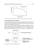
Radiation Diffraction. A special form of scattering due to x-ray diffraction is occasionally encountered in
radiographic inspection. Diffraction of radiation is observed most often in the radiography of thin testpieces having a
grain size large enough to be an appreciable fraction of the part thickness. Castings made of austenitic corrosion-resistant
and heat-resistant stainless steel or of Inconel and other nickel-base alloys are the products most likely to exhibit
diffraction in radiographs.
The radiographic appearance of this type of scattering can be confused with the mottled appearance sometimes produced
by porosity, segregation, or spongy shrinkage. Diffraction patterns can be distinguished from these conditions in the
testpiece by making successive radiographs with the testpiece rotated between exposures 1 to 5° about an axis
perpendicular to the beam. A mottled pattern due to porosity or segregation will be only slightly changed, but a pattern
due to diffraction effects will show a marked change. The radiographs of some testpieces will show mottling from both
diffraction and porosity, and careful interpretation of the radiographs is needed to differentiate between them.
Mottling due to diffraction can be reduced, and sometimes eliminated, by raising x-ray tube voltage and by using lead
screens. Filters will usually aid in the control of diffraction. Raising the tube voltage and filtration are often of positive
value even though radiographic contrast and sensitivity are reduced.
Sometimes, diffraction cannot be reduced. In such cases, two radiographs made as described above can be used to identify
diffraction.
Scattering at High Photon Energies. Lead screens should always be used when the radiation energy exceeds 1
MeV. Use of the usual 0.13 mm (0.005 in.) thick front screen and 0.25 mm (0.010 in.) thick back screen is both
satisfactory and convenient. Some users find 0.13 mm (0.005 in.) thick front and back screens adequate when filters are
used both front and back of the cassette or film holder. Other users consider 0.25 mm (0.010 in.) thick front and back
screens of value because of greater selective absorption of scattered radiation from the testpiece.
Filtration of the incident x-ray beam offers no improvement in radiographic quality. However, filters at the film improve
radiographs for the inspection of uniform sections.
Lead filters are most convenient for energies above 1 MeV. Care should be taken to minimize mechanical damage to the
filter because filter defects could be confused with characteristics of the material being inspected.
It is important to block off all radiation except the effective beam with heavy shielding at the anode. This is usually
recognized by manufacturers of high-voltage x-ray equipment. For example, in some linear accelerators, depleted-
uranium collimators confine the beams to a 22° included angle. Unless a high-energy x-ray beam is well collimated,
radiation striking the walls of the x-ray room will generate secondary radiation and thus seriously degrade the quality of
the radiograph. This will be especially noticeable if the testpiece is thick or has projecting parts that are not immediately
adjacent to the filter.
Radiographic Inspection
Revised by the ASM Committee on Radiographic Inspection
*
Interpretation of Radiographs
Proper identification of both the radiograph and the testpiece, clarity of the penetrameter, suitability of radiographic
techniques, adequacy of coverage, and the techniques of image processing in real-time systems or the precision and
uniformity of film processing in film radiography all offset the image that is being interpreted. Film radiographs and real-
time radiographs are interpreted similarly with respect to the recognition of flaws and testpiece features. The primary
difference is that film radiographs are negative images, while real-time radiographs are generally positive images (which
may also be enhanced with image processing).
A qualified interpreter must:
•
Define the quality of the radiographic image, which includes a critical analysis of the radiographic
procedure and the image-developing procedure
• Analyze the image to determine the nature and extent of any abnormal condition in the testpiece
• Evaluate the testpiece by comparing interpreted information with standards or specifications
• Report inspection results accurately, clearly, and within proper administration channels
Proper identification of both the radiograph and testpiece is an absolute necessity for correlation of the radiograph with
the corresponding testpiece. Identification includes both identification of the testpiece and identification of the view or
area of coverage.
Poor-quality film radiographs are usually reshot. However, reshooting radiographs increases inspection costs, not only
because the original setup must be duplicated and a new exposure made but also because the testpiece must be retrieved
and taken to the radiographic laboratory. With on-site radiography, which involves transporting radiographic equipment
to the site and returning the exposed films to the laboratory for processing, especially high costs may be involved when
poor-quality radiographs must be reshot. Table 12 lists some of the usual causes of poor quality in a radiographic image
and indicates the usual corrective action required to eliminate each cause.
Table 12 Probable causes and corrective action for various types of deficient image quality or artifacts on
processed radiographic film
Quality or artifact Probable cause
Corrective action
Overexposure
View with higher-intensity light. Check exposure (time and radiation
intensity); if as specified, reduce exposure 30% or more.
Overdevelopment
Reduce development time or developer temperature.
Density too high
Fog
See "Fog" below.
Underexposure
Check exposure (time and radiation intensity); if as specified,
increase exposure 40% or more.
Underdevelopment
Increase development time or developer temperature. Replace weak
(depleted) developer.
Density too low
Material between screen and film
Remove material.
High subject contrast
Increase tube voltage.
Contrast too high
High film contrast
Use a film with lower contrast characteristics.
Low subject contrast
Reduce tube voltage.
Contrast too low
Low film contrast
Use a film with higher contrast characteristics.
Underdevelopment
Increase development time or developer temperature. Replace weak
(depleted) developer.
Testpiece-to-film distance too
long
If possible, decrease testpiece-to-film distance; if not, increase source-
to-film distance.
Source-to-film distance too short
Increase source-to-film distance.
Focal spot (or -ray source) too
large
Use smaller source or increase source-to-film distance.
Screens and film not in close
contact
Ensure intimate contact between screens and film.
Poor definition
Film graininess too coarse
Use finer-grain film.
Light leaks in darkroom
With darkroom unlighted, turn on all lights in adjoining rooms; seal
any light leaks.
Exposure to safelight
Reduce safelight wattage. Use proper safelight filters.
Stored film inadequately protected
from radiation
Attach strip of lead to loaded film holder and place in film-storage
area. Develop test film after 2 to 3 weeks; if image of strip is evident,
improve radiation shielding in storage area.
Film exposed to heat, humidity, or
gases
Store film in a cool, dry place not subject to gases or vapors.
Overdevelopment
Reduce development time or developer temperature.
Developer contaminated
Replace developer.
Fog
Exposure during processing
Do not inspect film during processing until fixing is completed.
Finely mottled fog Stale film
Use fresh film.
Fog on edge or corner Defective cassette
Discard cassette.
Depleted developer
Replace developer solution.
Failure to use stop bath or to rinse
Use stop bath, or rinse thoroughly between developing and fixing.
Yellow stain
Depleted fixer
Replace fixer solution.
Dark circular marks Film splashed with developer
prior to immersion
Immerse film in developer with care.
Dark spots or
marblelike areas
Insufficient fixing
Use fresh fixer solution and proper fixing time.
Dark branched lines
and spots
Static discharge
Unwrap film carefully. Do not rub films together. Avoid clothing
productive of static electricity.
Dark fingerprints Touching undeveloped film with
chemically contaminated fingers
Wash hands thoroughly and dry, or use clean, dry rubber gloves.
Light fingerprints Touching undeveloped film with
oily or greasy fingers
Wash hands thoroughly and dry, or use clean, dry rubber gloves.
Dark spots or streaks Developer contaminated with
metallic salts
Replace developer solution.
Crescent-shaped light
areas
Faulty film handling
Keep film flat during handling. Use only clean, dry film hangers.
Light circular patches Air bubbles on film during
development
Agitate immediately upon immersion of film in developer.
Circular or dropshaped
light patches
Water or fixer splashed on film
before development
Avoid splashing film with water or fixer solution.
Light spots or areas Dust or lint between screens and
film
Keep screens clean.
Sharply outlined light
or dark areas
Nonuniform development
Agitate film during development.
Reticulation (leather-
grain appearance)
Temperature gradients in
processing solutions
Maintain all solutions at uniform, constant temperature.
Fixer solution too warm
Maintain correct temperature of the fixing solution.
Frilling (loosening of
emulsion from film
base)
Fixer solution depleted Replace fixer solution.
Personnel engaged in the interpretation of radiographs should possess certain qualifications. Some qualification
recommendations are included in personnel standards published by the American Society for Nondestructive Testing (Ref
6), several governmental agencies, and many private manufacturers. Usually, a minimum level of visual acuity, minimum
standards of education and training, and demonstrated proficiency are required of all interpreters of radiographs.
Viewing of radiographs should be carried out in an area with subdued lighting to minimize distracting reflections
from the viewing surface. Audible distractions, which interfere with concentration, can best be avoided by locating the
work area away from the main production floor or other high-noise area.
Radiographic film images are viewed on an illuminated screen. The viewing apparatus should have an opal-glass or
plastic screen large enough to accommodate the largest film to be interpreted. The screen should be illuminated from
behind with light of sufficient intensity to reveal variations in photographic density up to a nominal film density of at least
3.0. There may be a need for a smaller, more intensely illuminated viewer for evaluating small areas of film having
densities up to 4.5 or more. Viewing screens of high-intensity illuminators should be cooled by blowers or other suitable
apparatus to prevent excessive heat from damaging films and to extend lamp life.
When interpreting paper radiographs or xeroradiographs, specular light as from a spotlight or high-intensity lamp should
be directed onto the radiograph from the side at an angle of about 30°. Background lighting should be heavily subdued.
A densitometer can be provided for accurate evaluation of small variations in photographic density or for quantitative
evaluation of radiographic and processing techniques. A transmission densitometer is used with films, and a reflection
densitometer is used with paper radiographs.
Radiographic Acceptance Standards. Usually, a series of radiographs that exhibit various types and sizes of flaws
should be selected for acceptance standards. Parts that contain similar flaws should be performance tested to determine
the least acceptable condition. The radiograph of the least acceptable part then becomes the minimum acceptance standard
for similar parts. Often, the acceptance standard is defined as a length or area of the image that may contain no more than
a specified number of flaws of a given size and type. Certain types of flaws, such as cracks or incomplete fusion, may be
prohibited regardless of size. The interpreter must determine the degree of imperfection, as related to the minimum
acceptance standard, and then decide whether minimum soundness requirements have been met.
Obviously, no single standard can be applied universally to radiographic inspection. However, flaws that are frequently
encountered have been reproduced in sets of reference radiographs such as those published by ASTM (Table 13).
Reference radiographs depict various types of flaws that may occur in castings or weldments and are graded according to
flaw size and severity.
Table 13 Reference radiographs in ASTM standards
ASTM standard
Subject of radiographs in standard
E 155
Aluminum and magnesium castings
E 186
Heavy-wall (50-115 mm, or 2-4 in.) steel castings
E 192
Investment steel castings for aerospace applications
E 242
Appearance of radiographic images as certain parameters are changed
E 272
High-strength copper-base and nickel-copper alloy castings
E 280
Heavy-wall (115-300 mm, or 4 -12 in.) steel castings
E 310
Tin bronze castings
E 390
Steel fusion welds
E 431
Semiconductors and related devices
E 446
Steel castings up to 50 mm (2 in.) in thickness
E 505
Aluminum and magnesium die castings
E 689
Ductile cast irons
E 802
Gray iron castings up to 115 mm (4 in.) in thickness
Codes or specifications for radiographic inspection, particularly those that have been standardized by an industry through
a trade association or a professional society or those that have been adopted by a governmental agency or a prime
contractor, may refer to published reference radiographs. In such cases, the code or specification should designate one or
more reference radiographs in a specific set as the minimum standard for acceptance. Although it is considered most
desirable to have an acceptance standard that is based on actual service data, standardized codes or specifications usually
define rigid acceptance criteria that do not allow for variations in specific design features of similar products.
Reference cited in this section
6.
"No
ndestructive Testing Personnel Qualification and Certification, Supplement A, Radiographic Testing
Method," ASNT-TC-1A, American Society for Nondestructive Testing
Radiographic Inspection
Revised by the ASM Committee on Radiographic Inspection
*
Interpretation of Radiographs
Proper identification of both the radiograph and the testpiece, clarity of the penetrameter, suitability of radiographic
techniques, adequacy of coverage, and the techniques of image processing in real-time systems or the precision and
uniformity of film processing in film radiography all offset the image that is being interpreted. Film radiographs and real-
time radiographs are interpreted similarly with respect to the recognition of flaws and testpiece features. The primary
difference is that film radiographs are negative images, while real-time radiographs are generally positive images (which
may also be enhanced with image processing).
A qualified interpreter must:
•
Define the quality of the radiographic image, which includes a critical analysis of the radiographic
procedure and the image-developing procedure
• Analyze the image to determine the nature and extent of any abnormal condition in the testpiece
• Evaluate the testpiece by comparing interpreted information with standards or specifications
• Report inspection results accurately, clearly, and within proper administration channels
Proper identification of both the radiograph and testpiece is an absolute necessity for correlation of the radiograph with
the corresponding testpiece. Identification includes both identification of the testpiece and identification of the view or
area of coverage.
Poor-quality film radiographs are usually reshot. However, reshooting radiographs increases inspection costs, not only
because the original setup must be duplicated and a new exposure made but also because the testpiece must be retrieved
and taken to the radiographic laboratory. With on-site radiography, which involves transporting radiographic equipment
to the site and returning the exposed films to the laboratory for processing, especially high costs may be involved when
poor-quality radiographs must be reshot. Table 12 lists some of the usual causes of poor quality in a radiographic image
and indicates the usual corrective action required to eliminate each cause.
Table 12 Probable causes and corrective action for various types of deficient image quality or artifacts on
processed radiographic film
Quality or artifact Probable cause
Corrective action
Overexposure
View with higher-intensity light. Check exposure (time and radiation
intensity); if as specified, reduce exposure 30% or more.
Overdevelopment
Reduce development time or developer temperature.
Density too high
Fog
See "Fog" below.
Underexposure
Check exposure (time and radiation intensity); if as specified,
increase exposure 40% or more.
Underdevelopment
Increase development time or developer temperature. Replace weak
(depleted) developer.
Density too low
Material between screen and film
Remove material.
High subject contrast
Increase tube voltage.
Contrast too high
High film contrast
Use a film with lower contrast characteristics.
Low subject contrast
Reduce tube voltage.
Low film contrast
Use a film with higher contrast characteristics.
Contrast too low
Underdevelopment
Increase development time or developer temperature. Replace weak
(depleted) developer.
Testpiece-to-film distance too
long
If possible, decrease testpiece-to-film distance; if not, increase source-
to-film distance.
Source-to-film distance too short
Increase source-to-film distance.
Focal spot (or -ray source) too
large
Use smaller source or increase source-to-film distance.
Poor definition
Screens and film not in close
contact
Ensure intimate contact between screens and film.
Film graininess too coarse
Use finer-grain film.
Light leaks in darkroom
With darkroom unlighted, turn on all lights in adjoining rooms; seal
any light leaks.
Exposure to safelight
Reduce safelight wattage. Use proper safelight filters.
Stored film inadequately protected
from radiation
Attach strip of lead to loaded film holder and place in film-storage
area. Develop test film after 2 to 3 weeks; if image of strip is evident,
improve radiation shielding in storage area.
Film exposed to heat, humidity, or
gases
Store film in a cool, dry place not subject to gases or vapors.
Overdevelopment
Reduce development time or developer temperature.
Developer contaminated
Replace developer.
Fog
Exposure during processing
Do not inspect film during processing until fixing is completed.
Finely mottled fog Stale film
Use fresh film.
Fog on edge or corner Defective cassette
Discard cassette.
Depleted developer
Replace developer solution.
Failure to use stop bath or to rinse
Use stop bath, or rinse thoroughly between developing and fixing.
Yellow stain
Depleted fixer
Replace fixer solution.
Dark circular marks Film splashed with developer
prior to immersion
Immerse film in developer with care.
Dark spots or
marblelike areas
Insufficient fixing
Use fresh fixer solution and proper fixing time.
Dark branched lines
and spots
Static discharge
Unwrap film carefully. Do not rub films together. Avoid clothing
productive of static electricity.
Dark fingerprints Touching undeveloped film with
chemically contaminated fingers
Wash hands thoroughly and dry, or use clean, dry rubber gloves.
Light fingerprints Touching undeveloped film with
oily or greasy fingers
Wash hands thoroughly and dry, or use clean, dry rubber gloves.
Dark spots or streaks Developer contaminated with
metallic salts
Replace developer solution.
Crescent-shaped light
areas
Faulty film handling
Keep film flat during handling. Use only clean, dry film hangers.
Light circular patches Air bubbles on film during
development
Agitate immediately upon immersion of film in developer.
Circular or dropshaped
light patches
Water or fixer splashed on film
before development
Avoid splashing film with water or fixer solution.
Light spots or areas Dust or lint between screens and
film
Keep screens clean.
Sharply outlined light
or dark areas
Nonuniform development
Agitate film during development.
Reticulation (leather-
grain appearance)
Temperature gradients in
processing solutions
Maintain all solutions at uniform, constant temperature.
Fixer solution too warm
Maintain correct temperature of the fixing solution.
Frilling (loosening of
emulsion from film
base)
Fixer solution depleted Replace fixer solution.
Personnel engaged in the interpretation of radiographs should possess certain qualifications. Some qualification
recommendations are included in personnel standards published by the American Society for Nondestructive Testing (Ref
6), several governmental agencies, and many private manufacturers. Usually, a minimum level of visual acuity, minimum
standards of education and training, and demonstrated proficiency are required of all interpreters of radiographs.
Viewing of radiographs should be carried out in an area with subdued lighting to minimize distracting reflections
from the viewing surface. Audible distractions, which interfere with concentration, can best be avoided by locating the
work area away from the main production floor or other high-noise area.
Radiographic film images are viewed on an illuminated screen. The viewing apparatus should have an opal-glass or
plastic screen large enough to accommodate the largest film to be interpreted. The screen should be illuminated from
behind with light of sufficient intensity to reveal variations in photographic density up to a nominal film density of at least
3.0. There may be a need for a smaller, more intensely illuminated viewer for evaluating small areas of film having
densities up to 4.5 or more. Viewing screens of high-intensity illuminators should be cooled by blowers or other suitable
apparatus to prevent excessive heat from damaging films and to extend lamp life.
When interpreting paper radiographs or xeroradiographs, specular light as from a spotlight or high-intensity lamp should
be directed onto the radiograph from the side at an angle of about 30°. Background lighting should be heavily subdued.
A densitometer can be provided for accurate evaluation of small variations in photographic density or for quantitative
evaluation of radiographic and processing techniques. A transmission densitometer is used with films, and a reflection
densitometer is used with paper radiographs.
Radiographic Acceptance Standards. Usually, a series of radiographs that exhibit various types and sizes of flaws
should be selected for acceptance standards. Parts that contain similar flaws should be performance tested to determine
the least acceptable condition. The radiograph of the least acceptable part then becomes the minimum acceptance standard
for similar parts. Often, the acceptance standard is defined as a length or area of the image that may contain no more than
a specified number of flaws of a given size and type. Certain types of flaws, such as cracks or incomplete fusion, may be
prohibited regardless of size. The interpreter must determine the degree of imperfection, as related to the minimum
acceptance standard, and then decide whether minimum soundness requirements have been met.
Obviously, no single standard can be applied universally to radiographic inspection. However, flaws that are frequently
encountered have been reproduced in sets of reference radiographs such as those published by ASTM (Table 13).
Reference radiographs depict various types of flaws that may occur in castings or weldments and are graded according to
flaw size and severity.
Table 13 Reference radiographs in ASTM standards
ASTM standard
Subject of radiographs in standard
E 155
Aluminum and magnesium castings
E 186
Heavy-wall (50-115 mm, or 2-4 in.) steel castings
E 192
Investment steel castings for aerospace applications
E 242
Appearance of radiographic images as certain parameters are changed
E 272
High-strength copper-base and nickel-copper alloy castings
E 280
Heavy-wall (115-300 mm, or 4 -12 in.) steel castings
E 310
Tin bronze castings
E 390
Steel fusion welds
E 431
Semiconductors and related devices
E 446
Steel castings up to 50 mm (2 in.) in thickness
E 505
Aluminum and magnesium die castings
E 689
Ductile cast irons
E 802
Gray iron castings up to 115 mm (4 in.) in thickness
Codes or specifications for radiographic inspection, particularly those that have been standardized by an industry through
a trade association or a professional society or those that have been adopted by a governmental agency or a prime
contractor, may refer to published reference radiographs. In such cases, the code or specification should designate one or
more reference radiographs in a specific set as the minimum standard for acceptance. Although it is considered most