Volume 20 - Materials Selection and Design Part 8 potx
Bạn đang xem bản rút gọn của tài liệu. Xem và tải ngay bản đầy đủ của tài liệu tại đây (1.65 MB, 150 trang )
Fig. 20 Mechanical models and typical behavior. (a) Ideal Hookean solid ( = E
; spring model; elastic
response). (b) Ideal viscous Newtonian liquid ( =
; dashpot model). (c) Maxwell's mechanical model for a
viscoelastic material. (d) Voigt's mechanical model for a viscoelastic material. Source: Ref 29
Application of a deforming force (i.e., pulling) on the spring results in an immediate stretching and thus an immediate
strain. Once the force is released, the spring immediately recovers its initial length. Pulling with twice the force results
linearly in twice the strain. The case of the dashpot, however, is significantly different. When the "piston" has a force
applied to it, it slowly starts to move (no instant displacement as in the case of the spring), and when the force is released,
the dashpot stays in its new conformation. Once a force causes an ideal viscous polymer melt to flow, it remains in its
new position.
Two models, combining the spring and the dashpot either in series or parallel, have been developed that attempt to better
describe real polymer flow behavior. These models, Maxwell and Voigt, are named after their creators and are shown in
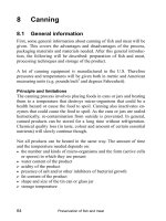
Fig. 20(c) and 20(d). Figure 21, very similar to Fig. 15, shows which mechanical analogs model different regions of the
log modulus versus temperature curve. The behavior shown in the Voigt model helps to explain the action known as
creep. Creep occurs when, under a static load for extended periods of time, increased strain levels slowly develop, as in
the case of a refrigerator that after many years distorts a linoleum floor. The Maxwell model describes stress relaxation,
which occurs when polymers are subjected to a constant strain environment. Over time, the molecules relax and orient
themselves to the strained position, thereby relieving stress. This occurs in applications such as threaded metal inserts into
plastic parts and threaded plastic bottle caps.
Fig. 21 Thermal dependence of elastic modulus for polys
tyrene. (a) Glassy region corresponding to Hookean
solid behavior. (b) Leathery region corresponding to Voigt model behavior. (c) Rubbery plateau region
corresponding to Maxwell model behavior. (d) Liquid flow region corresponding to Newtonian liquid behav
ior.
Source: Ref 30
References cited in this section
29.
M.M. McKelvey, Polymer Processing, John Wiley & Sons, 1962, p 26, 30
30.
J.M.G. Cowie, Polymers: Chemistry & Physics of Modern Materials,
2nd ed., Blackie Academic and
Professional, 1991, p 248
Effects of Composition, Processing, and Structure on Properties of Engineering Plastics
A M.M. Baker and C.M.F. Barry, University of Massachusetts Lowell
Properties of Engineering Plastics and Commodity Plastics
Engineering plastics generally offer higher moduli and elevated-service temperatures compared to the lower-cost, high-
volume, commodity plastics such as PE, PP, and PVC. These improved properties are due to chemical substituents,
inherently rigid backbones, and the presence of secondary attractive forces as discussed earlier in this article. Engineering
thermoplastics (e.g., POM, PC, PET, and polyether-imide, or PEI) are polymerized from more expensive raw materials,
and their processing requires higher energy input compared to that of commodity plastics, which is why the engineering
thermoplastics are more expensive.
Structures of Commodity Plastics. It is interesting to note the T
m
elevation of HDPE from LDPE. The effect of the
branched structure on density and morphology enables the high-density version to form more tightly packed crystalline
regions that require more thermal energy to overcome the cohesive forces keeping the plastic from melting. Substituting a
methyl group in place of a hydrogen, in the case of PP, increases T
m
and tensile strength further above that of HDPE. In
this case, steric hindrance due to the additional size of the methyl group stiffens the chain and restricts rotation. The
substitution of a large and highly electronegative chlorine atom in PVC prevents crystallization and also increases the
onset of T
g
, both due to steric hindrance effects and to the attractive polar forces generated. Polar attractive forces are so
extensive that the tensile strength can be seen to increase to 55 MPa. Polystyrene is amorphous and transparent due to the
atactic positioning of the pendant phenyl group, whose randomness destroys crystallinity. The tensile strength of PS is
less than that of PVC due to the lack of the highly polar pendant group.
Structures of Engineering Plastics. Phenylene and other ring structures (Table 1) attached directly into the
backbone often stiffen the polymer significantly, imparting elevated-thermal properties and higher mechanical properties
such as increased strength. Polyoxymethylene is essentially PE with an ether substitution, but it has a much higher T
m
(200 °C versus 135 °C for HDPE) because of its polarity. Both of these features promote a highly crystalline morphology.
The high dimensional stability, good friction and abrasion characteristics, and ease of processing of this polymer make it
a popular engineering plastic for precision parts.
Polycarbonate has an extended resonating structure because of the carbonate linkage. It has such a stiff backbone that
crystallization is impeded, and the resultant amorphous structure is transparent, much like PET. Physical properties of
PET, however, depend strongly both on its degree of crystallinity, which is governed by degree of orientation imparted
during processing, and on its annealing history. The high strength, ease of processing, and clarity of PET make it ideal for
soda bottles and polyester fibers. Polycarbonate has high strength, stiffness, hardness, and toughness over a range of -150
to 135 °C and can be reinforced with glass fibers to extend elevated-temperature mechanical properties. The high impact
strength of high-MW PC makes it suitable for applications such as motorcycle helmets. The carbonate linkage of PC
causes a susceptibility to stress cracking.
Polyetherimide has both imide groups and flexible ether groups, resulting in high mechanical properties but with enough
flexibility to allow processing. Its highly aromatic (presence of benzene rings) structure allows it to be used for specialty
applications.
Polyetheretherketone (PEEK), PPO, and PPS also rely on backbone benzene rings to yield high mechanical properties at
elevated temperatures. Both sulfur and oxygen are electronegative atoms, creating dipole moments that promote
intermolecular attractions and thus favorably affect elevated-temperature properties.
While the composition of thermoset plastics vary widely, the three-dimensional structure produced by cross-linking
prevents melting and hinders creep. Overall properties such as stiffness and strength are determined by the flexibility of
the polymer structure and the number of cross-links (cross-link density). Because epoxies, phenolics, and melamine
formaldehyde contain aromatic rings, they are typically rigid and hard. Epoxies are used for adhesives, assorted
electronics applications, sporting goods such as skis and hockey sticks, and prototype tooling for injection molding and
thermoforming. Melamine formaldehyde is easily colored and so is often found in household and kitchen equipment,
electronic housings, and switches. In contrast, phenolics are naturally dark colored and are limited to electronic and
related applications where aesthetics are less important. Silicones with their flexible ether linkages are softer and often
used as caulking and gasket materials. Thermoset polyurethanes vary widely from flexible to relatively rigid depending
on the chemical structure between urethane groups. Unsaturated polyesters are used for potting and encapsulating
compounds for electronics and in glass-fiber-reinforced molding compounds.
This discussion of the major commodity and engineering plastics is by no means complete. It is meant rather to include
concepts touched on earlier in evaluating structures in relation to their resultant properties.
Effects of Composition, Processing, and Structure on Properties of Engineering Plastics
A M.M. Baker and C.M.F. Barry, University of Massachusetts Lowell
Electrical Properties
Volume and/or surface resistivity, the dielectric constant, dissipation factor, dielectric strength, and arc or tracking
resistance are considered important electrical properties for design. These properties relate to structural considerations
such as polarity, molecular flexibility, and the presence of ionic impurities, which may result from the polymerization
process, contaminants, or plasticizing additives. Table 10 shows some typical electrical property values for selected
plastic materials.
Table 10 Electrical properties of selected plastics
Dielectric constant Dissipation factor Plastic Surface
resistivity,
Volume
resistivity,
· cm
Dielectric
strength,
kV/mm
At 50 Hz
At 10
6
Hz
At 50 Hz At 10
6
Hz
LDPE
10
13
>10
16
>70 2.3 2.3 2 × 10
-4
2 × 10
-4
PTFE
10
17
>10
18
60-80 2.1 2.1 2 × 10
-4
2 × 10
-4
PS
10
14
. . . . . . 2.6 . . . 0.5 × 10
-4
2.5 × 10
-4
PMMA
5 × 10
13
>10
15
30 3.7 2.6 0.060 0.015
PVC
. . . >10
15
20-40 3.5 2.7 0.003 0.002
Plasticized PVC
. . . 10
15
28 6.9 3.6 . . . . . .
POM
10
13
10
15
70 . . . 3.7 0.0015 0.0055
Nylon 6/6
. . . 10
15
(dry)
10
11
(wet)
40 (dry) 4.0 (dry)
6.0 (wet)
3.4 0.02 (dry)
0.20 (wet)
. . .
PET
6 × 10
14
2 × 10
14
60 3.4 3.2 0.002 0.021
PBT
5 × 10
13
5 × 10
13
>45 3.0 2.8 0.001 0.017
PC
>10
15
>10
16
>80 3.0 2.9 0.900 11
Modified PPO
10
14
>10
15
22 2.7 2.6 4 × 10
-4
9 × 10
-4
PAI
5 × 10
18
2 × 10
15
23 . . . 3.9 . . . 0.030
PEI
. . . 7 × 10
15
24 3.15 3.05 0.0015 0.0064
PSU
3 × 10
16
5 × 10
16
20 3.15 3.10 0.001 0.005
PEEK
. . . 5 × 10
16
19 3.20 . . . 0.003 . . .
Source: Ref 4
Volume resistivity is a measure of the resistance of an insulator to conduction of current. Most neat polymers have a
very high resistance to flow of direct current, usually 10
15
to 10
20
· cm compared to 10
-6
· cm for copper. Electrical
conductivity in normally insulating polymers results from the migration of ionic impurities and is affected by the mobility
of these ionic species. Generally, plasticizers with their increased mobility and high relative concentration of end groups
reduce resistivity and therefore increase electrical conductivity. Because absorption of water increases the mobility of
ionic species, this also reduces volume resistivity. Thus, the volume resistivity of nylon 6/6 is reduced by four decades
when the polymer absorbs water at ambient conditions. Addition of antistatic agents decrease surface resistivity because
the polar additives migrate to the surface of the polymer and absorb humidity. In contrast, conductive fillers, such as
carbon black powders and aluminum flake, can form three-dimensional pathways for conduction through insulating
polymer matrices. Finally, highly conjugated polymers such as polyacetylene and polyaniline provide sufficient electron
movement to reach semiconductor conductivity. For full conductivity, they rely on dopants.
Dielectric Constant and Dissipation Factor. In the presence of an electric field, polymer molecules will attempt to
align in that field. The dielectric constant (or permittivity), or ', is a measure of this polarization. While the dielectric
constant varies from 1 for a vacuum (where nothing can align) to 80 for water, the values for polymeters (shown in Table
10) are generally so low that most polymers are insulators. The dielectric constant also varies with temperature, rate or
frequency of measurement, polymer structure and morphology, and the presence of other materials in the plastic. The
dielectric constant of polymers typically peaks at the major thermal transition temperature (T
g
and/or T
m
) and then
decreases because of random thermal motions in the melt. As shown in Fig. 22(a), the dielectric constant decreases
abruptly as frequency increases.This occurs between 1 Hz and 1 MHz and is a result of the inability of the dipoles to align
with the high-frequency electric fields. The dielectric loss, '', is a measure of the energy lost to internal motions of the
material, and as shown in Fig. 22(b), peaks where the dielectric constant changes abruptly. The dissipation factor, tan ,
which is given by:
(Eq 8)
is a measure of the internal heating of plastics. Thus, little heating should occur in insulators (tan < 10
-3
), whereas high-
frequency welding necessitates that tan be much greater (Ref 32).
Fig. 22 Frequency dependence of the (a) dielectric constant and (b) dielectric loss. Source: Ref 31
Because polymer molecules are typically too long and entangled to align in electric fields, the dielectric constant usually
arises from shifting of the electron shell of the polymer and/or alignment of its dipoles in the field. For nonpolar
polymers, such as PTFE and PE, only electron polarization occurs and the dielectric constant can be approximated by:
= n
2
(Eq 9)
where n is the optical refractive index of the polymer. These values vary little with frequency, and changes occurring with
increased temperatures are caused by changes in free volume of the polymer. In contrast, the dielectric constants of polar
polymers, such as PVC and PMMA, are greater than n
2
and change substantially with temperature and frequency.
Backbone flexibility or ease of rotation of polar side groups allows some polymers to orient quickly and easily. If the
electric field alternates slowly enough, the molecule may be able to align or orient in the field depending upon its
flexibility and mobility. Consequently, relatively flexible polymers, such as PVC and PMMA, exhibit greater decreases in
dielectric constant with increased frequency than polymers, such as PEI and PSU, that have rigid backbones. The
additional free volume and mobility of the plasticized PVC allows the molecules to align with minimal delay; as shown in
Table 10, this doubles the dielectric constant at low frequencies.
Dielectric Strength. As the electric field applied to a plastic is increased, the polymer will eventually break down due
to the formation of a conductive carbon track through the plastic. The voltage at which this occurs is the breakdown
voltage, and the dielectric strength is this voltage divided by the thickness of the plastic. The dielectric strength decreases
with the thickness of the insulator because this prevents loss of internal heat to the environment. Dielectric strength is
increased by the absence of flaws.
Arc Resistance. In contrast to the dielectric strength, arc resistance is the ability of a polymer to resist forming a carbon
tracking on the surface of the polymer sample. Because these tracks usually emanate from impurities surrounding
electrical connections, arc resistance is measured by the track times. Polymers, such as PC, PS, PVC, and epoxies (which
have aromatic rings, easily oxidized pendant groups, or high surface energies), are prone to tracking (Ref 33) and exhibit
typical track times of 10 to 150 s (Ref 34). However, polyesters may have better tracking resistance than phenolics
because of the heteroatomic backbone that disrupts the carbon track. Nonpolar aliphatic compounds or those with strongly
bound pendant groups usually have better arc resistance; thus, the tracking times for PTFE, PP, PMMA, and PE are
greater than 1000 s (Ref 33).
References cited in this section
4. H. Dominghaus, Plastics for Engineers: Materials, Properties, and Applications, Hanser Publishers, 1988
31.
R.D. Deanin, Polymer Structure, Properties and Applications, Cahners Books, 1972, p 109
32.
W. Michaeli, Plastics Processing, an Introduction, Hanser Publishing, 1992, p 59
33.
C.C. Ku and R. Liepins, Electrical Properties of Polymers: Chemical Principles,
Hanser Publishers, 1987,
p 181-182
34.
A.B. Strong, Plastics: Materials and Processing, Prentice-Hall, 1996, p 144
Effects of Composition, Processing, and Structure on Properties of Engineering Plastics
A M.M. Baker and C.M.F. Barry, University of Massachusetts Lowell
Optical Properties
Transparency, opacity, haze, and color are all important characteristics of plastics. Optical clarity is achieved when light
is able to pass relatively unimpeded through a polymer sample. This is usually defined by the refractive index, n, which is
shown in Fig. 23 and given by:
(Eq 10)
where is the angle of incident light and is the angle of refracted light. While n for most polymers is 1.40 to 1.70, it
increases with the density of the polymer and varies with temperature. In order for a material to be clear, light has to be
transmitted with minimal refraction. Unstressed, homogeneous, amorphous polymers, such as PS, PMMA, and PC,
exhibit a single refractive index and thus are optically clear. However, when these polymers are severely oriented, and
therefore stressed, the areas with different refractive indices produce birefringence in the molded products. Because
amorphous, but heterogeneous, systems, such as the immiscible polymer blends ABS and HIPS, typically exhibit a
refractive index for each polymer phase, they are usually opaque or translucent. Semicrystalline polymers, such as HDPE
and nylon-6/6, effectively have two phases, the amorphous and crystalline regions. Consequently, semicrystalline
polymers are usually not transparent. Finally, introduction of any nonpolymeric phases, such as fillers or fibers, into the
plastic material induces opacity because these phases have their own refractive indices.
Fig. 23 Light refracted by a plastic sample
Optical clarity can also be controlled by polymerization techniques. When the refractive indices of multiphase systems are
matched, these plastics can be optically clear, but usually only over narrow temperature ranges. Neat poly-(4-methyl-1-
pentene) (TPX) is clear because the bulky side chains produce similar densities (0.83 g/cm
3
), and thus similar refractive
indices, in the amorphous and crystalline regions of the polymer. Matching of refractive indices of PVC and its impact
modifier is often used in transparent films for food packaging. Domains (second phases) that are smaller than the 400 to
700 nm wavelengths of visible light will not scatter visible light, and thus do not reduce clarity. In impact-modified
polymers, the minor rubbery phase is usually dispersed as particles with diameters greater than 400 nm, so most of them
are opaque. However, when the domains have diameters less than 400 nm or when the two phases form concentric rings
whose width is too narrow to scatter visible light, the blends are clear.
When crystals are smaller than the wavelength of visible light, they will also not scatter light and the plastic will be
optically clear or translucent. These crystal sizes can be controlled by quenching, use of nucleating agents, stretching, and
copolymerization. In quenching, the plastic melt is rapidly cooled below the transition temperature of the polymer. The
resultant reduction in thermal mobility of the polymer molecules limits crystal growth because the molecules are not able
to form ordered structures. While quenching is more easily accomplished with thin parts and films, nucleating agents can
reduce crystal size in a wider range of parts. The agents are small particles at which the crystallization process can begin.
Consequently, many such sites competing for polymer chains will reduce the average crystal size. Stretching also
promotes clarity because the mechanical stretching can break up large crystals, and the resultant thinner films are more
liable to transmit light without refraction. Finally, copolymerization can reduce the regularity of the polymer structure
enough to inhibit formation of large crystals. As discussed earlier, structural regularity is required of a polymer is to pack
into tightly order crystallites, and randomization of the structure results in smaller areas capable of being packed together.
The surface character of processed parts also controls optical properties. Smooth surfaces reflect and transmit light at
limited angles, whereas rough surfaces scatter the light. Consequently, smooth surfaces produce clear and glossy products
while rough surfaces appear dull and hazy. Because surface character is usually controlled by processing, it is discussed
in the next section.
Unmodified polymers are usually clear to yellowish in color. Other colors are produced by dispersing pigments or dyes
uniformly within the plastic. Poor dispersion can produce the marbled or speckled appearances favored for cosmetic
cases. However, degradation of polymers will produce yellowing or browning of the plastic. Polymers such as PVC,
which are particularly subject to degradation, are also discussed in the section "Processing" in this article.
Effects of Composition, Processing, and Structure on Properties of Engineering Plastics
A M.M. Baker and C.M.F. Barry, University of Massachusetts Lowell
Chemical Properties
Solubility is the ease with which polymer chains go into solution and is a measure of the attraction of the polymer to
solvent molecules. The old adage of "like dissolves like" can be explained by considering the balance of forces that occur
during dissolution of the polymer. Solubility is determined by the relative attraction of polymer chains for other polymer
chains and polymer chains for solvent molecules. If the polymer-solvent interactions are strong enough to overcome
polymer-polymer interactions, dissolution occurs; otherwise, the polymer remains insoluble. Swelling can be considered
as partial solubility because the solvent molecules penetrate the polymer, but they cannot completely separate the chains.
When solvents and polymers have similar polarities, the polymer will dissolve in or be swollen by the solvent. Because
longer chains are more entangled, higher MW hinders dissolution. Semicrystalline polymers are much harder to dissolve
than similar amorphous materials. The tightly packed crystalline regions are not easily penetrated because the solvent
molecules must overcome the intermolecular attractions. Elevated temperatures, which increase the mobility of solvent
molecules and polymer chains, facilitate dissolution. The presence of cross-links completely prevent dissolution, and such
polymers merely swell in solvents.
Plasticizers must be soluble in the polymer to prevent migration to the surface (blooming) and extraction by solvents.
Consequently, the relatively expensive primary plasticizers for PVC closely match the solubility of the polymer, while
less expensive secondary plasticizers are less compatible with the PVC.
Permeability is a measure of the ease with which molecules diffuse through a polymer sample. The low densities of
polymers compared with metals and ceramics allow enhanced permeation of species such as water, oxygen, and carbon
dioxide. If there are strong interactions between the polymer and the migrating species, adsorption will be high, but
permeation may be low as the migrating species is delayed from diffusing. For example, the electronegative chlorine
atoms substitution in polyvinylidene chloride (PVDC) enhances adsorption of oxygen, nitrogen, carbon dioxide, and
water while its tightly packed chain arrangement restricts diffusion of these species. Thus, PVDC films (commonly used
as plastic wrap) are extremely valuable in food packaging operations. As shown in Fig. 24, permeability can also be
inhibited by the addition of platelike fillers, which increase the distance that water must travel in order to pass completely
through the plastic.
Fig. 24
Barrier pigment effect. Water passes relatively unobstructed through a polymer with spherical additives
(a), but must travel around platelike fillers (b). Source: Ref 35
Environmental stress cracking occurs when a stressed plastic part is exposed to a weak solvent, often moisture. The stress
imparts strain to the polymer, which allows the solvent to penetrate and either extract small molecules of low
n
, or to
plasticize and weaken the polymer. The stress then causes fracture at these weak areas. Polymers which are exposed to
UV light are particularly susceptible to environmental stress cracking. Resistance is enhanced when the permeability of
the polymer to water is low.
Reference cited in this section
35.
M.J. Austin, Inorganic Anti-Corrosive Pigments, Paint and Coating Testing Manual,
J.V. Koleste, Ed.,
ASTM, 1995, p 239
Effects of Composition, Processing, and Structure on Properties of Engineering Plastics
A M.M. Baker and C.M.F. Barry, University of Massachusetts Lowell
Processing
Most thermoplastic processing operations involve heating, forming, and then cooling the polymer into the desired shape.
This section briefly outlines the most common plastics manufacturing processes. The factors that must be considered
when processing engineering thermoplastics are also discussed. These include melt viscosity and melt strength;
crystallization; orientation, die swell, shrinkage, and molded-in stress; polymer degradation; and polymer blends.
Overview of the Major Thermoplastics Processing Operations. Although there are a number of variants, the
major thermoplastics processing operations are extrusion, injection molding, blow molding, calendering, thermoforming,
and rotational molding. Characteristics of each of these processes are described briefly below. Additional information is
provided in the article "Design for Plastics Processing" in this Volume.
Extrusion is a continuous process used to manufacture plastics film, fiber, pipe, and profiles. The single-screw extruder
is most commonly used. In this extruder, a hopper funnels plastic pellets into the channel formed between the helical
screw and the inner wall of the barrel that contains the screw. The extruder screw typically consists of three regions: a
feed zone, a transition or compression zone, and a metering or conveying zone (see Fig. 10 in the article "Design for
Plastics Processing" in this Volume). The feed zone compacts the solid plastic pellets so that they move forward as the
solid mass. As the screw channel depth is reduced in the transition zone, a combination of shear heating and conduction
from the heated barrel begins to melt the pellets. The fraction of unmelted pellets is reduced until finally in the metering
zone a homogeneous melt has been created. The continuous rotation of the screw pumps the plastic melt through a die to
form the desired shape.
The die and ancillary equipment produce different extrusion processes. With blown-film extrusion, air introduced through
the center of an annular die produces a bubble of polymer film; this bubble is later collapsed and wound on a roll. In
contrast, flat film is produced by forcing the polymer melt through a wide rectangular die and onto a series of smooth
cooled rollers. Pipes and profiles are extruded through dies of the proper shape and held in that form until the plastic is
cooled. Fibers are formed when polymer melt is forced through the many fine, cylindrical openings of spinneret dies and
then drawn (stretched) by ancillary equipment. In extrusion coating, low-viscosity polymer melt from a flat-film die flows
onto a plastic, paper, or metallic substrate. However, in wire coating, wire is fed through the die and enters the center of
the melt stream before or just after exiting the die. Finally, coextrusion involves two or more single-screw extruders that
separately feed polymer streams into a single die assembly to form laminates of the polymers. Typical extrusion pressures
range from 1.5 to 35 MPa.
While single-screw extruders provide high shear and poor mixing capabilities, they produce the high pressures needed for
processes such as blown and flat-film extrusion. Screw designs are changed to improve mixing, to shear gel (unmelted
polymer) particles, and to provide more efficient melting. The latter designs are particularly critical to the extrusion of PE
films where partially melted polymer particles are not desirable.
In addition to single-screw extruders, twin-screw extruders are available. While twin-screw extruders use two screws to
convey the polymer to a die, the configuration of the screws produce different conveyance mechanisms. Intermeshing
twin-screw extruders transfer the polymer from channel to channel, whereas nonintermeshing twin-screw extruders like
single-screw extruders push the polymer down the barrel walls. In addition, intermeshing corotating twin-screw
extruders tend to move the polymer in a figure-eight pattern around the two screws. Because this produces more shear and
better mixing, corotating twin-screw extruders are well suited to mixing and compounding applications. Intermeshing
counterrotating twin-screw extruders channel the polymer between the two screws. Twin-screw extruders also permit
tighter control of shear because twin screws are usually not a single piece of metal, but two rods on which component
elements are placed. Consequently, screw profiles can be "programmed" to impart specific levels of shear.
In contrast to the single- and twin-screw extruders, ram extruders have no screw, but merely use a high-pressure ram to
force the polymer through a die. This provides for minimal shear and much higher pressures than available in single-
screw extruder. However, ram extrusion is a batch operation, not a continuous operation.
Injection molding is a batch operation used to rapidly produce complicated parts. Plastic pellets are fed through a
hopper into the feed zone of a screw and melted in much the same way as occurs in a single-screw or ram extruder.
However, rather than being forced through a die, in an injection-molding machine the melt is accumulated and
subsequently forced under pressure into a mold by axial motion of the screw. This pressure is typically quite high and for
rapid injection and/or thin-walled parts can exceed 100 MPa. Once the part has cooled sufficiently, the mold is opened,
the part ejected, and the cycle recommences. The use of multiple-cavity molds allows for simultaneous production of a
large number of parts, and often little finishing of the final part is required. Polymer from multiple plasticating units
(extruders) can also be injected sequentially into the same mold to form "coinjected" parts. In gas-assisted injection
molding, gas is injected into the melt stream and accumulates in thicker sections of the part, whereas in foam processes
the introduced gas forms small pockets (cells) throughout the melt.
Blow molding operations generate hollow products, such as soda bottles and automobile fuel tanks. The three basic
processes are continuous extrusion, intermittent extrusion, and injection blow molding. In continuous-extrusion blow
molding, a tube of polymer is continuously extruded. Pieces of this tube (called parisons) are cut off, inserted into the
mold, and stretched into the cavity of the blow mold by air pressure. Although intermittent extrusion blow molding is
similar, the tube of plastic is injected from the extruder rather than continuously extruded. In the injection blow molding
process. a plastic preform, which for bottles resembles a test tube with threads, is injected molded. Then this preform is
brought to the forming temperature (either as part of the cooling from injection molding or after being reheated) and
expanded into the blow mold. Stretch blow molding is a variant of the blow-molding process, in which the preform is
stretched axially by mechanical action and then expanded in the transverse direction to contact the walls of the mold.
Calendering uses highly polished precision chromium rolls to transform molten plastic continuously into sheet (>0.25
mm) or film ( 0.25 mm) for floor coverings. This process can also be used to coat a substrate, for example, cords coated
with rubber for automotive tire use (Ref 36). Usually an extruder provides a reservoir of plastic melt, which is then passed
between two to four calender rolls whose gap thickness and pressure profiles determine the final gage of the sheet being
formed. Chill rolls are used to reduce the sheet temperature, and a windup station is generally required to collect the sheet
product.
Thermoforming operations are used to produce refrigerator liners, computer housings, food containers, blister
packaging, and other items that benefit from its low tooling costs and high output rates. In this process, infrared or
convection ovens heat an extruded or calendered sheet to its rubbery state. Mechanical action, vacuum and/or air pressure
force the heated sheet into complete contact with cavity of the thermoforming mold.
Rotational molding, or rotomolding, involves charging a polymeric powder or liquid into a hollow mold. The mold is
heated, and then cooled, while being rotated on two axes. This causes the polymer to coat the inside of the mold. Because
rotomolding produces hollow parts with low molded-in stresses, it is often used for chemical containers and related
products where environmental stress crack resistance is required. It can also be used for hollow parts with complicated
geometries that cannot be produced by blow molding.
Melt viscosity and melt strength are major factors to be considered when choosing a resin and a processing
operation. While flexible polymers are generally less viscous than polymers with more rigid structures, MW, MWD, and
additives are used to tailor plastics for specific processes. Resins are typically rated by their melt index, which is the flow
of the melt (in grams per 10 min) through a geometry and under a load specified by ASTM D 1238 (Ref 37). Although
this generates the flow at very low shear rates, it is an indication of the melt viscosity of the plastic. Extrusion blow
molding processes require that the melt index be below 2 g per 10 min, whereas other extrusion processes require
somewhat greater flow. In contrast, high-melt-index resins (6 to 60 g per 10 min) are necessary in extrusion coating,
injection molding, and injection blow molding.
Low-viscosity polymers such as nylon 6/6 tend to leak (drool) from the nozzles of injection-molding machines, so they
require special nozzles for injection molding. Aliphatic nylons exhibit narrow melting ranges and so need special screws
in which the transition zone is relatively short, typically two or three turns (flights). Molecular weight distribution also
factors into the extrusion of relatively low-viscosity polymers such as PEs. A wider MWD provides easier processing, but
is detrimental to final properties such as strength and heat sealing. Narrower MWDs, particularly with linear polymers
such as HDPE and LLDPE, often necessitate changes to extruder.
High-viscosity polymers, such as PC and PSU, typically require high injection pressures and clamping tonnages. If,
however, the pressure required to fill the cavity exceeds the maximum injection pressure for the press, then the cavity is
underfilled. When the injection pressure is greater than clamp pressure (tonnage), then the melt can force its way through
the parting line (where the mold opens to eject the finished part) and damage the mold. The former problem is common in
high-speed or thin-wall injection molding of PC and other high-viscosity resins. While increasing processing temperatures
does decrease the melt viscosity, increased plasticating (screw) speeds do not reduce viscosity much due to the rigid
backbones of PC and PSU, which extend the lower Newtonian plateau beyond the shear rates typical of plasticating units.
However, high shear is still produced during injection and can break the polymer chains, which lowers mechanical
properties, such as the impact strength of PC. High-flow resins (melt index > 40 g per 10 min) are available, but these
generally exhibit lower MWs with the corresponding changes in properties. Other high-flow resins, which are usually
immiscible blends of the primary polymer with a higher-flow plastic or additive, also affect final thermomechanical
properties.
Very-high MW or very rigid structures produce polymers that are not truly melt processible. In high-MW materials such
as ultrahigh-molecular-weight polyethylene (UHMWPE) and PTFE, the intermolecular attraction and excessive chain
length do not allow the materials to melt. Heat will soften these polymers, but they are usually processed as slurries in
which a solvent or oil carries the unmolten polymer particles. Because this requires excessive pressure, PTFE is often
processed using a ram extruder. Ultrahigh-molecular-weight polyethylene needs less pressure, but is also processed on
ram or twin-screw extruders to prevent excessive shearing (as is discussed later in this article). The high MW ( 10
6
Daltons, Ref 38) of the PMMA used for Plexiglas (trademark of Rohm and Haas Corp.) sheet does not permit melt
processing, but rather the sheet is cast (polymerized) from the monomer (molding grade PMMA resins have MWs in the
range of 60,000 Daltons, Ref 38).
The very inflexible structures of polyimides and aromatic polyamides do not permit melt processing. While polyimides
are cast, more flexible variations, such as PEI and polyamide-imide (PAI) are melt processible. Similarly, copolymers and
other variants of PTFE are melt processible. In both cases, the properties of the melt-processible polymers are less than
those of the originals. Polyphenyl oxide is barely processible. However, blends of PPO with PS or HIPS are.
Additives such as processing aids and colorants can severely alter the viscosity of a polymer. It is not unusual for the
same polymer compounded in different colors to have very different flow characteristics. Fillers and fibers typically
increase melt viscosity. High loadings of fine particulate fillers, such as carbon black and titanium dioxide, can alter the
low shear-rate behavior of the plastic; because these materials exhibit yield stresses, more force or pressure is required to
initiate movement of the molten polymer. Regrind (processed polymer from runners and sprues) is often recombined with
the virgin resin. However, because the regrind usually has a lower MW than the virgin resin, the flow characteristics of
the mixture differ from those of the neat polymer.
Control of viscosity is critical in several processes. In coextrusion, the polymers must form layers and not mix with each
other. Thus, the maximum viscosity difference for multimanifold dies is 400 to 1, whereas it is 2 or 3 to 1 for feed blocks
where the molten layers are in contact longer. In gas-assisted injection molding, the polymer viscosity determines where
the bubble will form. Viscosity also allows the polymer flow in rotary molding and extrusion coating.
Melt strength is the ability of the molten polymer to hold its shape for a period of time. Because long entangled polymer
chains produce melt strength, these resins are high-MW polymers (with the related low-melt index values). However,
polymers, such as PS, PET, and some nylons, which do not permit sufficient entanglement, always have low melt
strength. Consequently, the processing equipment must accommodate this. Fiber extrusion lines usually place the extruder
two or three floors above the windup units and draw the low-melt-strength fibers with gravity. This technique has also
been used in blown-film extrusion of nylons. Polystyrene and PET are generally processed using flat-film extrusion so
that the melt flows from the die to chill rollers that support the melt. As discussed earlier, biaxially oriented PET films are
then produced by heating the flat film to its rubbery state and stretching it on a center frame. Low-melt-strength polymers
must always be injection blow molded.
Sheet materials used for thermoforming require hot strength to prevent excessive sagging of the rubbery polymeric sheet
during heating. While this strength is also related to the MW and MWD, it incorporates the transition temperatures of the
polymer. Because amorphous polymers exhibit broad transitions from their T
g
to the molten state, they are easily
thermoformed. The sharper melting transitions of polymers, such as PP, PET, and nylons, provide narrow processing
temperature ranges and tend to be either too solid to form or too molten and sag. Broadening of the MWD of PP and
copolymerization of PET have produced grades of these resins suitable for thermoforming. There are also special
techniques that use the ductility of PP to thermoform parts.
Crystallization has two components: nucleation and crystal growth. Nucleation is the initiation of crystallization at
impurities in the polymer melt and is enhanced by rapid cooling rates and nucleating agents. Crystal growth is favored by
slower cooling rates (which allows the molecules enough thermally induced mobility to assume a crystalline structure).
Although the maximum crystallinity occurs if the polymer is held at 0.9 T
m
(K), the degree of crystallinity developed is a
function of the temperatures achieved and how long the molten plastic is kept warm. Consequently, because rapid cooling
produces no crystallinity or many small crystallites, it is used to produce optically clear PE-blown film and blow-molded
PET bottles. Slower cooling or annealing which produces fewer, but larger, crystals is not always favored because
mechanical properties such as impact strength are adversely affected. Moreover, while the intermolecular bonding that
occurs in a crystalline polymer results in improved mechanical and thermal properties, the desire for crystalline, stress-
annealed parts is balanced by economics, which usually dictate that plastics be cooled as rapidly as possible to reduce
production time.
The volumetric changes (tight molecular packing) associated with crystallization produce shrinkage in plastics products.
Consequently, the semicrystalline plastics shrink far more than amorphous plastics, and the degree of shrinkage varies
with the cooling rate. Typical shrinkage values are presented in Table 11, but the incorporation of additives such as
fillers and glass fibers, which interrupt or enhance crystallinity can affect shrinkage. Because flexible polymers, such as
aliphatic nylons and PP, exhibit high levels of shrinkage, particularly in thick cross sections, they reduce shrinkage during
extrusion by utilizing the high pressures of ram extruders to process the polymers slightly below their melting
temperatures.
Table 11 Typical shrinkage values for selected polymers
Shrinkage, mm/mm Polymer
Polymer Polymer
with 30% glass fiber
HDPE
0.015-0.040
0.002-0.004
PP
0.010-0.025
0.002-0.005
PS
0.004-0.007
. . .
ABS
0.004-0.009
0.002-0.003
POM
0.018-0.025
0.003-0.009
Nylon 6/6
0.007-0.018
0.003
PET
0.020-0.025
0.002-0.009
PBT
0.009-0.022
0.002-0.008
PC
0.005-0.007
0.001-0.002
PSU
0.007 0.001-0.003
PPS
0.006-0.014
0.002-0.005
Source: Ref 39
Crystallinity can also vary through the thickness of a part with the rapidly cooled outside surfaces and the slowly cooled
core having different levels of crystallinity. This effect, which varies with polymer type and processing conditions, can
alter plastic properties. With flexible polymers, such as PP, crystallization occurs throughout the thickness. However, at
relatively slow injection speeds and low mold temperatures, relatively rigid polymers, such as syndiotactic PS,
polyphenyl sulfide (PPS), and polyketones, produce layers of amorphous polymer at the surface and core of the part with
a semicrystalline region between these layers (Ref 40). At high temperatures, these polymers behave more like PP.
Orientation. Different levels of orientation and the related phenomena of die swell, shrinkage, and molded-in stress
are introduced during processing. Because gravity is the only force acting on the melt during rotational molding, very
little orientation occurs in this process. Uniaxial orientation results from pipe, profile, flat-film and fiber extrusion, and
calendering, whereas blow molding and blown-film extrusion induce biaxial orientation. While the actual orientation in
injection molding varies with the mold design, the high flow rates generally align the polymer molecules in the direction
of flow. Thermoforming also orients the polymer chains according to the design of the product.
Die swell is the expansion of the polymer melt that occurs as the extruded melt exits the die. This occurs when the
aligned polymer chains escape the confines of the die and return to their random coil configuration. Die swell is
dependent on processing conditions, die design, and polymer structure. It typically increases with screw speed (output
rate) and decreases with higher melt temperatures and longer die land lengths. Increased MW, which produces more
entanglement, also increases die swell.
Melt Fracture. At high extrusion rates, the polymer surface may also exhibit sharkskin or melt fracture. When the shear
stress during extrusion exceeds the critical shear stress for the polymer, a repeating wavy pattern known as sharkskin
occurs. In high-MW polyolefins this may disappear as the shear rate reaches the stick/slip region where the defect is
present, but not visible. At even higher speeds, the polymer surface breaks up again in the defect known as melt fracture.
This is particularly important in continuous and intermittent extrusion blow molding where these high-MW polymers are
used; the output rates for continuous extrusion blow molding are typically below the critical shear rate, while those for
intermittent extrusion blow molding place the process in the stick/slip region.
Shrinkage. Although shrinkage results from the volumetric contraction of the polymer during cooling, it is influenced
by the relaxation of oriented polymer molecules. During processing the polymers align in the direction of flow, and their
relaxation causes swelling perpendicular to this direction. Consequently, shrinkage in the direction of flow is usually
much greater than transverse to flow. Addition of fillers and fibers, which also align in the flow, reduces shrinkage
because they prevent the aligned molecules from relaxing. While rapid cooling can prevent the aligned polymer chains
from relaxing, these chains contribute to molded-in stress.
Molded-in stress is the worst in regions where the polymer chains are highly aligned and not allowed to relax. Thus,
processes with high levels of orientation produce the greatest molded-in stress. The stressed areas are points of attack for
chemicals and sources of future breaks and cracks. Annealing will remove some of these stresses and is routinely required
for some polymers such as PSUs. Because processes such as thermoforming and injection blow molding do not actually
melt the plastic, but shape it at lower temperatures, the stretching produces high levels of molded-in stress. Usually the
gate region of an injection-molded part will have the highest stresses, and consequently gate location is an important
consideration in part design and failure analysis.
Polymer Degradation. Polyvinyl chloride, other chlorine-containing polymers, fluoropolymers, and POM tend to
degrade under normal processing conditions. The dehydrochlorination of PVC occurs relatively easily and requires tightly
controlled processing conditions. Hydrochloric acid formed during the degradation of PVC is not only corrosive to the
equipment, but it catalyzes further degradation. The remaining polymer becomes increasingly rigid and discolored due to
the formation of conjugated carbon-carbon double bonds. A similar reaction occurring in fluoropolymers produces the
equally corrosive hydrofluoric acid. In contrast, POM depolymerizes from the ends of the polymer in an action called
"unzipping"; this produces formaldehyde, which further catalyzes the depolymerization. To prevent or minimize
degradation of PVC (or other chloropolymers and fluoropolymers), stabilizers are added to the plastic. With POM,
copolymerization with cyclic ethers (such as ethylene oxide) or incorporation of blocking groups at the ends of the
polymers (end capping) prevents unzipping.
Because many engineering polymers were produced by condensing two components to produce water, the presence of
water during melt processing reverses this reaction. Thus, chains are broken, the MW is reduced, and properties decrease.
In addition, water migrates to the surface of the part, resulting in the visual defect known as splay. While water uptake
varies with the polarity and storage conditions of the plastic, most engineering plastics require drying before processing.
Of the polymers shown in Table 12, only HDPE, PP, and rigid PVC are usually processed without some drying. While
undried ABS and PMMA will not exhibit chain scission, they are typically dried to prevent splay. The remaining
polymers in Table 12 are subject to chain scission and visual defects. Control of the water content in PET is of major
importance for clarity of blow-molded bottles.
Table 12 Water absorption, processing temperatures, and maximum shear conditions for selected polymers
Polymer Water
absorption, %
Processing
temperatures, °C
Maximum shear
stress, MPa
Maximum shear
rate, 10
3
s
-1
HDPE
<0.01 180-240 0.20 40
PP
0.01-0.03 200-260 0.25 100
PMMA
0.10-0.40 240-260 0.40 40
PVC, rigid
0.04-0.40 140-200 0.20 20
ABS
0.20-0.45 200-260 0.30 50
POM
0.25-0.40 190-230 0.45 40
Nylon 6/6
1.00-2.80 270-320 0.50 60
PET
0.10-0.20 280-310 0.50 . . .
PBT
0.08-0.09 220-260 0.40 50
PC
0.15 280-320 0.50 40
PS
0.30 310-340 0.50 50
Source: Ref 8, 39
The combination of temperature and shear can also degrade plastics. The long entangled polymer chains of UHMWPE
are easily severed in single-screw extruders. Heat-sensitive polymers such as PVC also degrade when the viscous
dissipation from shear raises the melt temperature above the degradation temperature. Because counterrotating twin-screw
extruders have positive material conveying characteristics, uniform residence time, and uniform temperature distributions,
they are used for extruding materials such as rigid PVC. Ultrahigh-molecular-weight polyethylene is often processed on
twin-screw extruders or ram extruders (which have little shearing action). While shear can be a problem in extrusion
processes, it is usually greatest in injection molding where polymer is forced at high velocities through small orifices. As
indicated in Table 12, the processing temperatures and maximum shear conditions vary from polymer to polymer.
However, as mentioned previously, when forcing highly viscous melts through thin channels, these maximum values are
easily exceeded. Excess shear rates produce chain scission, whereas excess shear stress tends to produce cracking and
related defects in the plastics product.
When continuous-glass fibers or glass mats are processed using traditional thermoset processing techniques, the glass
fibers usually remain unbroken. However, the discontinuous glass fibers commonly added to engineering resins are often
broken during plastication and molding. As shown in Fig. 25, the fiber length is critical to the strength of the "composite."
Reduction of the fiber length below a critical value results in a rapid decrease in strength. Consequently, glass fibers are
often compounded into polymers using the controlled shear of twin-screw extruders. Special nonreturn valves (at the end
of screws in injection-molding machines) also minimize fiber degradation.
Fig. 25 The effect of fiber length on material strength. Source: Ref. 41
Blends. The properties of immiscible and partially miscible blends depend on their processing conditions. Some are
engineered so that one phase migrates to the air interface and governs surface properties. In immiscible polyblends,
morphology is very sensitive to temperature and shear. These determine the size of the domains and whether the domains
are spherical, elongated, or laminar. Phases may elongate in the flow direction.
References cited in this section
8. L.L. Clements, Polymer Science for Engineers, Engineering Plastics, Vol 2,
Engineered Materials
Handbook, ASM International, 1988, p 56-57
36.
W. Michaeli, Plastics Processing, an Introduction, Hanser Publishing, 1992, p 159
37.
ASTM D 1238, Annual Book of ASTM Standards, Vol 08.01, ASTM
38.
J.A. Brydson, Plastics Materials, 5th ed., Butterworths, 1989, p 382
39.
Modern Plastics Encyclopedia '92, McGraw-Hill, 1992, p 378-428
40.
Y. Ulcer, M. Cakmak, J. Miao, and C.M. Hsiung, Structural Gradients Developed in Injection Molded
Syndiotactic Polystyrene (S-PS), Annual Technical Conference of the Society of Plastics Engineers,
1995, p
1788
41.
P.K. Mallick, Fiber-Reinforced Composites, Marcel Dekker, 1988, p 83
Effects of Composition, Processing, and Structure on Properties of Engineering Plastics
A M.M. Baker and C.M.F. Barry, University of Massachusetts Lowell
References
1. J.A. Brydson, Plastics Materials, 5th ed., Butterworths, 1989
2. R.J. Cotter, Engineering Plastics Handbook of Polyarylethers, Gordon and Breach, 1995
3. R.D. Deanin, Polymer Structure, Properties and Applications, Cahners Books, 1972
4. H. Dominghaus, Plastics for Engineers: Materials, Properties, and Applications, Hanser Publishers, 1988
5. F. Rodriguez, Principles of Polymer Systems, 3rd ed., Hemisphere Publishing, 1989
6. J.H. Schut, Why Syndiotactic PS Is Hot, Plast. Technol., Feb 1993, p 26-30
7. R.D. Deanin, Polymer Structure, Properties and Applications, Cahners Books, 1972, p 27
8. L.L. Clements, Polymer Science for Engineers, Engineering Plastics, Vol 2,
Engineered Materials
Handbook, ASM International, 1988, p 56-57
9. F. Rodriguez, Principles of Polymer Systems, 3rd ed., Hemisphere Publishing, 1989, p 23
10. H. Dominghaus, Plastics for Engineers: Materials, Properties, and Applications,
Hanser Publishers, 1988,
p 34, 347
11. R.D. Deanin, Polymer Structure, Properties and Applications, Cahners Books, 1972, p 54
12. S.L. Rosen, Fundamental Principles of Polymeric Materials,
2nd ed., John Wiley & Sons, 1993, p 53, 54,
59
13. R.D. Deanin, Polymer Structure, Properties and Applications, Cahners Books, 1972, p 55
14. J.M. Dealy and K.F. Wissbrun,
Melt Rheology and Its Role in Plastics Processing; Theory and
Applications, Van Nostrand Reinhold, 1990, p 369
15. R.D. Deanin, Polymer Structure, Properties and Applications, Cahners Books, 1972, p 130
16. J.A. Brydson, Plastics Materials, 5th ed., Butterworths, 1989, p 58
17. R.D. Deanin, Polymer Structure, Properties and Applications, Cahners Books, 1972, p 141
18. R.D. Deanin, Polymer Structure, Properties and Applications, Cahners Books, 1972, p 138
19. S.L. Rosen, Fundamental Principles of Polymeric Materials, 2nd ed., John Wiley & Sons, 1993, p 45
20. S.L. Rosen, Fundamental Principles of Polymeric Materials, 2nd ed., John Wiley & Sons, 1993, p 46
21. F. Rodriguez, Principles of Polymer Systems, 3rd ed., Hemisphere Publishing, 1989, p 23-24
22. W. Michaeli, Plastics Processing, an Introduction, Hanser Publishing, 1992, p 19
23. C.C. Winding and G.D. Hiatt, Polymeric Materials, McGraw-Hill, 1961
24. R.D. Deanin, Polymer Structure, Properties and Applications, Cahners Books, 1972, p 89
25. R.D. Deanin, Polymer Structure, Properties and Applications, Cahners Books, 1972, p 342
26. R.D. Deanin, Polymer Structure, Properties and Applications, Cahners Books, 1972, p 240
27. C. Rauwendaal, Polymer Extrusion, 2nd ed., Hanser Publishers, 1990, p 182
28. C. Rauwendaal, Polymer Extrusion, 2nd ed., Hanser Publishers, 1990, p 218
29. M.M. McKelvey, Polymer Processing, John Wiley & Sons, 1962, p 26, 30
30. J.M.G. Cowie, Polymers: Chemistry & Physics of Modern Materials,
2nd ed., Blackie Academic and
Professional, 1991, p 248
31. R.D. Deanin, Polymer Structure, Properties and Applications, Cahners Books, 1972, p 109
32. W. Michaeli, Plastics Processing, an Introduction, Hanser Publishing, 1992, p 59
33. C.C. Ku and R. Liepins, Electrical Properties of Polymers: Chemical Principles,
Hanser Publishers, 1987,
p 181-182
34. A.B. Strong, Plastics: Materials and Processing, Prentice-Hall, 1996, p 144
35. M.J. Austin, Inorganic Anti-Corrosive Pigments, Paint and Coating Testing Manual,
J.V. Koleste, Ed.,
ASTM, 1995, p 239
36. W. Michaeli, Plastics Processing, an Introduction, Hanser Publishing, 1992, p 159
37. ASTM D 1238, Annual Book of ASTM Standards, Vol 08.01, ASTM
38. J.A. Brydson, Plastics Materials, 5th ed., Butterworths, 1989, p 382
39. Modern Plastics Encyclopedia '92, McGraw-Hill, 1992, p 378-428
40.
Y. Ulcer, M. Cakmak, J. Miao, and C.M. Hsiung, Structural Gradients Developed in Injection Molded
Syndiotactic Polystyrene (S-PS), Annual Technical Conference of the Society of Plastics Engineers,
1995,
p 1788
41. P.K. Mallick, Fiber-Reinforced Composites, Marcel Dekker, 1988, p 83
Effects of Composition, Processing, and
Structure on Properties of Composites
R. Laramee, Intermountain Design Inc.
Introduction
COMPOSITES fabricated with fiber reinforcement and a resin, carbon, or metal matrix are versatile materials that offer
several advantages for today's innovative and demanding designs. In general, composites are lightweight, strong, and
impact and fatigue resistant. They can be cost competitive, and are adaptable to many applications. Composites can be
readily tailored in composition and manufacturing processing to meet specific engineering-design applications and
loading conditions.
This article describes the interaction of composition, manufacturing process and composite properties and how variations
in the composition, manufacturing, shop process instructions, and loading/environmental conditions can affect the use of
a composite product in a performance/service life operation.
For composite matrix and reinforcement systems, the reinforcement type and orientation will in most instances be the
dominant contributor to properties. With the use of good coupling agents, the reinforcement and matrix can be more
effective in working together to resist all loading conditions. Fillers can be used effectively to lower density and cost,
change strength properties, and facilitate the manufacturing process.
Generally, in manufacturing, a longer process time with a higher pressure and temperature will result in higher properties
and an improved product. Knowledge of the environment and the loading conditions will enable the design/manufacturing
product team to specify any necessary coatings, optimal structural cross sections, a maintenance schedule, and inspection
criteria that will anticipate possible problems.
However, in the actual application of composites to primary and secondary structures a trade-off among weight, cost,
size, and stress/deflections with other materials composites may not be the answer for every problem. As existing and
future designs for mass vehicles such as automotive, trains, ships, and aircraft are evaluated, a hybrid mixture of metal
alloys and composites may provide the optimal solutions. An open, creative, and aggressive mind plus good material
databases and unique design concepts will go far to provide a balanced materials application to a broadening field of
problem solutions.
The design properties of resin-matrix composites are based on a standard composition and a standard processing cure,
with planned variations to meet specific design applications. Standard compositions range from a 33 to 66% matrix
material plus a 33 to 66% reinforcing fiber. These percentages hold true for resin-, carbon-, and metal-matrix
compositions. For resin-matrix composites, the standard processing cures include pressures from 0 to 1700 kPa (0 to 250
psi), temperatures from room temperature to 177 °C (350 °F), and time at maximum temperature of 1 h/in. of component
thickness.
Databases of mechanical and thermal properties versus temperature exist for standard materials, as supplied by prepreg
suppliers such as Thiokol Inc. and Fiberite Inc. for resin-matrix composites, and as developed in-house for carbon- and
metal-matrix products by other manufacturers, for various processing cycles. The following discussion provides data on
matrix composition, manufacturing, and mechanical properties.
Effects of Composition, Processing, and Structure on Properties of Composites
R. Laramee, Intermountain Design Inc.
Composition of Composites
For a standard composite panel or structural shape, the ratio of matrix material (resin, metal, or carbon) to the fiber
reinforcement ranges approximately from 1:2 to 2:1. The fiber is the main tailoring element for design properties, while
fiber orientation and fillers can provide secondary fine tuning for the product application.
The resin, carbon, or metal matrix provides (1) stable dimensional control to the fiber laminate, (2) a small participating
component for properties, and (3) a shear resistance between reinforcing fibers. A coupling agent enhances resin matrix-
to-fiber bonding, while the filler can fine tune such properties as density, cost/pound, processing viscosity, strength, and
flame-retardant characteristics.
Reinforcing-fiber characteristics such as density; fiber diameter, strength, and modulus; fiber-filament bundle size; and
woven-fiber fabric type or chopped-fiber form are initially optimized approximately by the "rule of mixtures" to help
meet the composite properties needed for the design application engineering criteria for product operation and
performance.
In addition, the selection of the ratio of matrix to reinforcement constituents is influenced by the loading patterns to the
product, environmental operating conditions, the standard manufacturing-processing methods, reinforcement forms, costs,
and completion time for the particular company and industry.
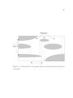
Reinforcement forms for the various matrix systems are shown in Fig. 1. Table 1 identifies a short list of current
reinforcements, matrix materials, and coupling agents. Most frequently used reinforcements include:
• Uniaxial continuous fiber for end-tape filament winding, braiding, or pultrusion
• Fabric (warp and fill continuous fiber) for tape wrapping and lay-up fabrication processes
• Chopped, continuous short-fiber reinforcement for molding compounds, injection or resin-
transfer
molding, and bulk- or sheet-molding compound as a charge for compression molding
Coupling agents are added to assist the binding of organic and inorganic fibers to the resin matrix.
Table 1 Types of materials used in composites
Fiber reinforcements
Inorganic
Glass
Boron/tungsten wire
Silicon carbide
Organic
Aramid (Kevlar)
Carbon
Graphite
Matrix materials
Resin
Thermoplastic
Polyester
Polyamide
Polysulfone
Thermoset (virgin or carbonized)
Epoxy
Phenolic
Polyester
Polyimide
Bismaleimide
Pitch
Metal
Stainless steel alloy
Aluminum alloy
Titanium alloy
Carbon
Carbonized resin
CVD carbon or graphite deposition
Carbon powder
Filler
Powder
Silica
Carbon
Microballoon
Phenolic
Carbon
Glass
Solid particles
Carbon
Silicon carbide
Ceramic
Resin-fiber coupling agents
Silane
Source: Ref 1, 2, 3
Fig. 1 Reinforcement forms for resin-, carbon-, and metal-matrix composite systems. Source: Ref 1, 2
Resin, carbon, or metal matrix, with or without fillers, can be added to the reinforcement fibers or woven fabric as a
partially staged resin (partially solidified, stabilized, or cured liquid resin) or as a metal sheet or foil or powder form, or
matrix material can be added to the fibers (in situ) during placement onto or into the open- or closed-mold surface. The
matrix can be in the form of a liquid, powder, particles, foil, sheet, or fiber.
Fillers or additives can replace up to 33% of the weight of a resin matrix to tailor composite properties for such
characteristics as density, wear resistance, color, ductility, flame-smoke retardation, moisture resistance, lubricity, and
dimensional stability. The components added to the resin matrix will also change the cost per pound, the softening and
gelation of the final cure process and a change of the service temperature.
Currently, twelve or more fiber-reinforcement systems are available for resin-matrix-composite fabrication into industrial,
commercial, and aerospace products. However, this article concentrates mainly on four fiber types: glass, aramid, carbon,
and graphite. Figure 2 shows a comparison of the fiber characteristics and properties. Density ranges from 1.44 to 2.48
g/cm
3
, strength from a minimum of 2200 MPa (320 ksi) to a maximum of 4585 MPa (665 ksi), and modulus from 85 to
345 GPa (12 to 50 × 10
6
psi), and service-temperature capability in inert atmospheres from 500 to 3040 °C (930 to 5500
°F). Reinforcements for metal- and carbon-matrix composites are shown in Table 2. Typical property variations for three
reinforcements are:
Tensile
strength
Elastic
modulus
Reinforcement Density,
g/cm
3
MPa
ksi GPa
10
6
psi
Boron metal deposited on a carbon fiber
2.3 5030
730
400 58
Alumina powder pressed, sintered, and formed into fiber
<4.0 450 65 205 30
Table 2 Reinforcements for metal- and carbon-matrix composites
Diameter Tensile strength Tensile modulus
Fiber Density
gm/cm
3
m in
GPa 10
6
psi GPa 10
6
psi
Metal-matrix reinforcements: boron and alumina fibers
Boron-tungsten
2.6 100-200
3950-7850
5.5-7.0
0.80-1.0
400 58
Boron-carbon
2.3 100-200
3950-7850
5.0 0.73 400 58
14
(b)
2.0
(b)
390
(b)
57
(b)
-alumina
(a)
3.95 20 790
19
(c)
2.8
(c)
390
(c)
57
(c)
Melting
point
Tensile
strength
Young's
modulus
of elasticity
Material Specific
gravity
°C °F MPa
ksi GPa
10
6
psi
Coefficient
of thermal
expansion,
10
-6
/K
Metal-matrix reinforcements: metallic wires
Aluminum
2.71 660 1220
290 40 68.9
10.0 23.6
Beryllium
1.85 1350
2460
1100
160
310 45.0 11.6
Copper
8.90 1083
1980
413 60 124 18.0 16.5
Tungsten
19.3 3410
6170
2890
130
345 50.0 4.6
Austenitic stainless steel
7.9 1539
2800
2390
350
200 29.0 8.5
Molybdenum
10.2 2625
4750
2200
320
331 48.0 . . .
Tensile strength Tensile modulus Material Density,
g/cm
3
GPa 10
6
psi GPa 10
6
psi
Metal-matrix reinforcements: short fibers and whiskers
Alumina
Whiskers
4.0 10-20 1-3 700-1500
100-220
Sintered fibers
<4.0 0.2-0.7
0.030-0.10
140-300 20-40
Boron, thermally formed fibers
2.3 2.75 0.400 400 60
Boron nitride, fibers
1.8-2.0 0.3-1.4
0.045-0.20
28-80 4-10
Silicon nitride, whiskers
3.2 5-7 0.75-1.0 350-380 50-55
Carbon-matrix reinforcements
Carbon whiskers
>2.0 . . . . . . 700 100
Carbon fibers
1.8-2.0 2-3 0.29-0.44 230-550 35-80
Source: Ref 4
(a)
Slurry-spun continuous fiber.