ENCYCLOPEDIA OF ENVIRONMENTAL SCIENCE AND ENGINEERING - BIOLOGICAL TREATMENT OF WASTEWATER doc
Bạn đang xem bản rút gọn của tài liệu. Xem và tải ngay bản đầy đủ của tài liệu tại đây (795.1 KB, 23 trang )
137
B
BIOLOGICAL TREATMENT OF WASTEWATER
1. INTRODUCTION
Biological treatment is the most widely used method for
removal, as well as partial or complete stabilization of bio-
logically degradable substances present in waste-waters.
Most often, the degradable substances are organic in nature
and may be present as suspended, colloidal or dissolved
matter. The fraction of each form depends on the nature of
wastewater. In the operation of biological treatment facili-
ties, the characteristics of wastewater are measured in terms
of its chemical oxygen demand, COD, biochemical oxygen
demand, BOD, total organic carbon, TOC, and volatile sus-
pended solids, VSS; concepts of which have been discussed
elsewhere.
1
Most of the conventional biological wastewater treat-
ment processes are based on naturally occurring biologi-
cal phenomena, but are carried out at accelerated rates.
These processes employ bacteria as the primary organ-
isms; however, certain other microorganisms may also
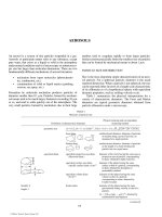
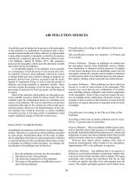
play an important role. Gates and Ghosh
2
have presented
the biological component system existing in the BOD pro-
cess and it is shown in Figure 1. The degradation and sta-
bilization of organic matter is accomplished by their use
as food by bacteria and other microorganisms to produce
protoplasm for new cells during the growth process. When
a small number of microorganisms are inoculated into a
bacteriological culture medium, growth of bacteriawith
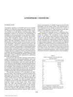
time follows a definite pattern as depicted in Figure 2 by
plotting viable count and mass of bacteria against time.
3
The population dynamics of bacteria in biological treat-
ment processes depends upon various environmental fac-
tors including pH, temperature, type and concentration
of substrate, hydrogen acceptor, availability and concen-
tration of essential nutrients like nitrogen, phosphorous,
sulfur, etc., and essential minerals, osmotic pressure, tox-
icity of media or by-products, and degree of mixing.
4
In
recent years, cultures have been developed for biological
treatment of many hard-to-degrade organic wastes.
2. METABOLIC REACTIONS
The metabolic reactions occurring within a biological treat-
ment reactor can be divided into three phases: oxidation, syn-
thesis and endogenous respiration. Oxidation–reduction may
proceed either in the presence of free oxygen, aerobically,
or in its absence, anaerobically. While the overall reactions
SUBSTRATE
ORGANICS
OXYGEN
GROWTH
FACTORS
LYSISED
PRODUCTS
OXYGEN
BACTERIA
(PRIMARY FEEDERS)
DEAD
BIOMASS
AUTO-
DESTRUCTION
OXYGEN
GROWTH
FACTORS
CO
2
CO
2
H
2
O
H
2
O
ENERGY
ENERGY
OTHER PRODUCTS
OTHER
PRODUCTS
CO
2
H
2
O
ENERGY
OTHER
PRODUCTS
P
R
O
T
O
Z
O
A
B
A
C
T
E
R
I
A
PROTOZOA
(SECONDARY FEEDERS)
FIGURE 1 Biological component system existing in BOD process.
© 2006 by Taylor & Francis Group, LLC
138 BIOLOGICAL TREATMENT OF WASTEWATER
carried out may be quite different under aerobic and anaero-
bic conditions, the processes of microbial growth and energy
utilization are similar. Typical reactions in these three phases
are formulated below:
• Organic Matter Oxidation (Respiration)
C
x
H
y
O
z
+ O
2
→ CO
2
+ H
2
O + Energy
• Inorganic Matter Oxidation (Respiration)
NH O NO H O 2H Energy
42 3 2
ϩϪ ϩ
ϩϩ2 →+
• Protoplasm (Cell Material) Synthesis
C
x
H
y
O
z
+ NH
3
+ O
2
+ Energy → C
5
H
7
NO
2
+ H
2
CHO H NO Energy
xyz 3
ϩϩ ϩ
ϩϪ
→
C
5
H
7
NO
2
+
CO
2
+ H
2
O
• Protoplasm (Cell Material) Oxidation
C
5
H
7
NO
2
+ 5O
2
→ 5CO
2
+ 2H
2
O + NH
3
+ Energy
Therefore, bacterial respiration in living protoplasm is a
biochemical process whereby energy is made available for
endothermic life processes. Being dissimilative in nature,
respiration is an important process in wastewater treat-
ment practices. On the other hand, endogenous respira-
tion is the internal process in microorganisms that results
in auto-digestion or self-destruction of cellular material.
3
Actually, bacteria require a small amount of energy to main-
tain normal functions such as motion and enzyme activation
and this basal-energy requirement of the bacteria has been
designated as endogenous respiration. Even when nutri-
ents are available, endogenous metabolism proceeds with
the breakdown of protoplasm.
5
According to Bertalanffy’s
hypothesis,
6
the microbial growth is the result of competition
between two opposing processes: Aufban—assimilation, and
Abban—endogenous metabolism. The rate of assimilation is
proportional to the mass of protoplasm in the cell and the
surface area of the cell, whereas the endogenous metabolism
is dependent primarily on environmental conditions.
In the presence of enzymes produced by the living micro-
organisms, about 1/3 of the organic matter removed is oxi-
dized into carbon dioxide and water in order to provide energy
for synthesis of the remaining 2/3 of the organic matter into
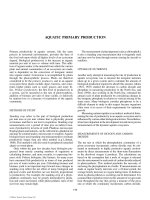
the cell material. Metabolism and process reactions occur-
ring in typical biological wastewater treatment processes are
explained schematically by Stewart
7
as shown in Figure 3.
Thus, the basic equations for biological metabolisms are:
Organic matter metabolized
= Protoplasm synthesized ϩ Energy for synthesis
and
Net protoplasm accumulation
= Protoplasm synthesized Ϫ Endogenous respiration.
“Growth Kinetics”
Irvine and Schaezler
8
have developed the following
expression for non-rate limited growth of microorganisms
in logarithmic phase:
d
d
N
t
kNϭ
0
(1)
510 g
INFLUENT
INFLUENT
BOD
5
510 g
250 g
350 g
275 g
525 g
105 g
160 g
ASSIMILATIVE
BOD
5
BOD
5
REMOVED
BIOMASS
FORMED
O
2
O
2
O
2
R
E
S
P
I
R
A
T
I
O
N
ASSIMILATIVE
R
E
S
P
I
R
A
T
I
O
N
R
E
S
P
I
R
A
T
I
O
N
E
N
D
O
G
E
N
O
U
S
RESPIRATION
120 g
40 g
10 g
E
N
D
O
G
E
N
O
U
S
R
E
S
P
I
R
A
T
I
O
N
ACTIVE BIOMASS
INACTIVE
B
I
O
M
A
S
S
BIOMASS
EFFLUENT
BOD UNUSED
SYSTEM METABOLISM FOR SOLUBLE WASTES
INFLUENT
BOD
BOD
(SOLUBLE
AND VSS)
ASSIMILATED
SYNTHESIZED
BIOMASS
BIOMASS GROWTH
UNUSED BOD (SOLUBLE AND VSS)
INFLUENT NON-BIODEGRADABLE FSS AND VSS
WASTE = SOLUBLES + PARTICULATES
EFFLUENT
EXCESS
SLUDGE
RESPIRATION
FIGURE 3 Metabolism and process reactions.
Time
Time
Log
Growth Phase
Declining
Growth Phase
Endogenous Phase
Mass of Microorganisms
LAG
Phase
LOG
Phase
Declining
Growth
Phase
Stationary
Phase
Increasing
Death Phase
Log
Death Phase
Death
Number of Visible Microorganisms
FIGURE 2 Growth pattern of microorganisms.
© 2006 by Taylor & Francis Group, LLC
BIOLOGICAL TREATMENT OF WASTEWATER 139
or
N
t
ϭN
o
e
k
o
t
where:
N
0
= Number of viable microorganisms per unit volume at
time t = 0
N
t
= N = Number of viable microorganisms per unit volume
at time t
and
k = Logarithmic growth rate constant, time
Ϫ 1
.
In wastewater treatment practices, the growth pattern
based on mass of microorganisms has received more atten-
tion than the number of viable microorganisms. If each
microorganism is assumed to have an average constant mass,
then N in Eq. 1 can be replaced with X , the mass of active
microorganisms present per unit volume to obtain:
d
d
X
t
kXϭ
0
.
(2)
The growth of bacterial population may become limited
either due to exhaustion of available nutrients or by the accu-
mulation of toxic substances. The growth rate of bacteria
starts slowing down, and Eq. 1 changes to the form:
d
d
N
t
kN
t
ϭ
(3)
where growth rate factor k
t
, varies with time and becomes a
function of temperature, T , pH, substrate concentration, S ,
and concentration of various nutrients, C
n 1
, C
n 2
, etc., i.e.:
k
t
= V
1
( T , pH, C
s
, C
n 1
, C
n 2
, … ).
Figure 4 shows variation in growth rate k
t
with change in
nutrient concentrations, assuming that T and pH are held con-
stant and substrate concentration, S , is greater than the critical
substrate concentration, S
*
, above which k
t
, is independent
of S. Several interesting observations are made from these
curves.
8
First, the maximum value of k
t
is essentially constant.
Second, the shape of the curve and the limiting concentration
is different for each nutrient. Third, k
t
is shown to be zero
when any of the nutrients is missing. Fourth, as the biological
reaction proceeds, all nutrients are consumed. Thus, even if
all nutrients are initially in excess, the growth may eventually
become limited. Finally, as the concentration drops to zero, a
stationary phase is reached, i.e., d N /d t becomes zero.
In case of a substrate limited system, rate of growth is
given by:
d
d
N
t
Nϭ m
(4)
or
d
d
X
t
Xϭ .
The following simple relationship between specific growth
rate of microorganisms, µ , and substrate concentration, S,
was developed by Monod
9
and has been widely accepted:
ϭ ϭ ϭ
ϩ
d
d
d
d
N
Nt
X
Xt
S
KS
m
max
(5)
where K is a constant called half velocity coefficient and µ
max
is maximum specific growth rate.
It is postulated that the same amount of substrate is incor-
porated in each cell formed. Therefore, the rate of increase
in number or mass of microorganisms in logarithmic growth
phase, d N /d t, or d X /d t, is proportional to the rate of substrate
consumption, d S /d t, or d L /d t, if the substrate concentration
is measured in terms of its BOD, L , and the following rela-
tionship can be stated:
d
d
d
d
X
t
Y
S
t
ϭ
(6)
or
∆ X = Y ∆ S
where Y is called the growth yield coefficient, ∆ X is the
cell mass synthesized in a given time, and ∆ S is substrate
removed in the same time. The substrate utilization rate, q,
per unit biomass has been defined as:
q
S
Xt
ϭ
d
d
(7)
0
0
C
n
2
C
n
1
*
C
n
1
C
n
1
+ C
n
2
*
*
k
max
k (C
n
1
, C
n
2
)
k vs C
n
2
(C
n
1
> C
n
1
)
*
k vs C
n
1
(C
n
2
> C
n
2
)
FIGURE 4 k vs nutrient concentration.
© 2006 by Taylor & Francis Group, LLC
140 BIOLOGICAL TREATMENT OF WASTEWATER
Combining Eqs. 4, 6 and 7 yields:
q
Y
ϭ
(8)
and
S
KS
ϭ
ϩ
max
.
(9)
Under conditions of rate limited growth, i.e., nutrient
exhaustion or auto-oxidation, Eq. 6 becomes:
d
d
d
d
X
t
Y
S
t
bXϭϪ
(10)
where b is the auto-oxidation rate or the microbial decay rate.
In absence of substrate, this equation is reduced to:
d
d
X
t
bXϭϪ.
(11)
Several kinetic equations have been suggested for analy-
sis and design of biological wastewater treatment systems
and the following have been applied frequently:
10 – 13
d
d
S
t
qSX
KS
ϭ
ϩ
max
(
)
(12)
d
d
S
t
qSXϭ
(13)
d
d
S
t
qX
S
S
ϭ
2
0
(14)
where S
0
is the initial substrate concentration. Combining
Eqs. 10 and 12 gives the net specific growth rate:
ϭϭ
ϩ
Ϫ
d
d
X
Xt
qYS
KS
b
max
(15)
A similar kinetic relationship can be obtained by combining
Eq. 10 with Eqs. 13 and 14.
Effect of Temperature
One of the significant parameters influencing biological
reaction rates is the temperature. In most of the biologi-
cal treatment processes, temperature affects more than one
reaction rate and the overall influence of temperature on the
process becomes important. The applicable equation for the
effect of temperature on rate construct is given by:
k
T
= k
20
u
T– 20
(16)
where u is the temperature coefficient. This equation shows
that reaction rates increase with increase in temperature.
Methods of BOD Removal
In wastewater treatment processes, the microorganisms are not
present as isolated cells, but are a collection of microorganisms
such as bacteria, yeast, molds, protozoa, rotifers, worms and
insect larvae in a gelatinous mass.
13
These microorganisms
tend to collect in a biological floc, called biomass, which is
expected to possess good settling characteristics. The bio-
logical oxidation or stabilization of organic matter by the
microorganisms present in the floc is assumed to proceed in
the following sequence:
13,14
(a) An initial high rate of BOD removal from waste-
water on coming in contact with active biomass
by adsorption and absorption. The extent of this
removal depends upon the loading rate, the type of
waste, and the ecological condition of the biomass.
(b) Utilization of decomposable organic matter in direct
proportion to biological cell growth. Substances
concentrating on the surface of biomass are
decomposed by the enzymes of living cells, new
cells are synthesized and end products of decom-
position are washed into the water or escape to the
atmosphere.
(c) Oxidation of biological cell material through
endogenous respiration whenever the food supply
becomes limited.
(d) Conversion of the biomass into settleable or oth-
erwise removable solids.
The rates of reactions in the above mechanisms depend upon
the transport rates of substrate, nutrients, and oxygen in case
of aerobic treatment, first into the liquid and then into the
biological cells, as shown in Figure 5.
15
Any one or more of
these rates of transport can become the controlling factors in
obtaining the maximum efficiency for the process. However,
most often the interfacial transfer or adsorption is the rate
determining step.
14
In wastewater treatment, the biochemical oxygen demand
is exerted in two phases: carbonaceous oxygen demand to
oxidize organic matter and nitrogenous oxygen demand
to oxidize ammonia and nitrites into nitrates. The nitroge-
nous oxygen demand starts when most of the carbonaceous
oxygen demand has been satisfied.
15
The typical progression
of carbonaceous BOD removal by biomass with time, during
biological purification in a batch operation, was first shown
by Ruchhoft
16
as reproduced in Figure 6. The corresponding
metabolic reactions in terms of microorganisms to food ratio,
M/F, are shown in Figure 7. This figure shows that the food
to microorganisms ratio maintained in a biological reactor is
of considerable importance in the operation of the process.
At a low M/F ratio, microorganisms are in the log-growth
phase, characterized by excess food and maximum rate of
metabolism. However, under these conditions, the settling
characteristic of biomass is poor because of their dispersed
© 2006 by Taylor & Francis Group, LLC
BIOLOGICAL TREATMENT OF WASTEWATER 141
continued aertion under these conditions results in auto-
oxidation of biomass. Although the rate of metabolism is
relatively low at high M/F ratio, settling characteristics of
biomass are good and BOD removal efficiency is high.
Goodman and Englande
17
have suggested that the total
mass concentration of solids, X
T
, in a biological reactor is
composed of an inert fraction, X
i
, and a volatile fraction, X
v
,
which can be further broken down into an active fraction, X,
and non-biodegradable residue fraction, X
n
, resulting from
endogenous respiration, i.e.:
X
T
= X
i
+ X
v
= X
i
+ X + X
n
. (17)
The total mass concentration of solids in wastewater treat-
ment is called suspended solids, whereas its volatile fraction
is called volatile suspended solids, X. In a biological reac-
tor, volatile suspended solids, X, is assumed to represent the
mass of active microorganisms present per unit volume.
3. TOXICITY
Toxicity has been defined as the property of reaction of a
substance, or a combination of substances reacting with each
other, to deter or inhibit the metabolic process of cells without
completely altering or destroying a particular species, under a
given set of physical and biological environmental conditions
for a specified concentration and time of exposure.
18
Thus, the
toxicity is a function of the nature of the substance, its concen-
tration, time of exposure and environmental conditions.
Many substances exert a toxic effect on biological oxida-
tion processes and partial or complete inhibition may occur
depending on their nature and concentration. Inhibition may
result from interference with the osmotic balance or with
the enzyme system. In some cases, the microorganisms
become more tolerant and are considered to have acclima-
tized or adapted to an inhibitory concentration level of a
toxic substance. This adaptive response or acclimation may
result from a neutralization of the toxic material produced by
the biological activity of the microorganisms or a selective
CELL
CELL MEMBRANE
LIQUID FILM
LIQUID FILM
BY-
PRODUCT
OXYGEN
SUBSTRATE
BIOCHEM. REACTION
RD
R
1
R
2
R
2
R
2
R
2
REACTOR
DISSOLVED
DISSOLVED
OXYGEN
SUBSTRATE
SUBSTRATE
C
C
∆r
PRODUCTS
CO
2
O
2
CELL
B
I
O
C
H
E
M
I
C
A
L
REACTION
WASTE
PRODUCTS
SUBSTRATE
TRACE
ELEMENTS
FLOC PARTICLE
O
2
O
2
O
2
O
2
R
2
R
2
∆r
FIGURE 5 Mass transfer in biofloc.
0 2 4 8 12 16 20 24
Aeration time, hr
Oxidized
Net adsorbed and synthesized
0
10
20
40
50
60
70
80
90
100
30
Reduction of total carbonaceous oxygen demand, (%)
Total BOD
FIGURE 6 Removal of organic inbalance by biomass in a batch
operation.
0.2 0.5
1
235
10
20
0
0.5
1.0
UNUSED
BOD
ASSIMILATIVE
RESPIRATION
INITIAL SYNTHESIS
ENDOGENOUS
RESPIRATION
NET BIOMASS INCREASE
SHORT-TERM
AERATION
CONVEN-
TIONAL
EXTENDED
AERATION
RELATIVE ORGANISM WEIGHT (M/F)
DISPOSITION OF ASSIMILATED BOD
FIGURE 7 Metabolic reactions for the complete spectrum.
growth; also, the BOD removal efficiency is poor as the
excess unused organic matter in solution escapes with the
effluent. On the other hand, high M/F ratio means the opera-
tion is in the endogenous phase. Competition for a small
amount of food available to a large mass of micro organisms
results in starvation conditions within a short duration and
© 2006 by Taylor & Francis Group, LLC
142 BIOLOGICAL TREATMENT OF WASTEWATER
growth of the culture unaffected by the toxic substance. In
some cases, such as cyanide and phenol, the toxic substances
may be used as substrate. Rates of acclimation to lethal fac-
tors vary greatly. Thus, the toxicity to microorganisms may
result due to excess concentrations of substrate itself, the
presence of inhibiting substances or factors in the environ-
ment and/or the production of toxic by-products.
19 – 23
The influence of a toxicant on microorganisms depends
not only on its concentration in water, but also on its rate
of absorption, its distribution, binding or localization in the
cell, inactivation through biotransformation and ultimate
excretion. The biotransformations may be synthetic or non-
synthetic. The nonsynthetic transformations involve oxida-
tion, reduction or hydrolysis. The synthetic transformation
involve the coupling of a toxicant or its metabolite with a
carbohydrate, an amino acid, or a derivative of one of these.
According to Warren
19
, the additive interaction of two toxic
substances of equal toxicity, mixed in different proportions,
may show combined toxicity as shown in Figure 8. The com-
bined effects may be supra-additive, infra-additive, no inter-
action or antagonism. The relative toxicity of the mixture is
measured as the reciprocal of median tolerance limit.
Many wastewater constituents are toxic to microorgan-
isms. A fundamental axiom of toxicity states that all com-
pounds are toxic if given to a text organism at a sufficiently
high dose. By definition, the compounds that exert a delete-
rious influence on the living microorganisms in a biological
treatment unit are said to be toxic to those microorganisms.
At high concentrations, these substances kill the microbes
whereas at sublethal concentrations, the activity of microbes
is reduced. The toxic substances may be present in the influent
stream or may be produced due to antagonistic interactions.
Biological treatment is fast becoming a preferred option
for treating toxic organic and inorganic wastes in any form;
SUPRA-ADDITIVE INTERACTION
STRICTLY ADDITIVE INTERACTION
INFRA-ADDITIVE INTERACTION
NO INTERACTION
ANTAGONISM
SOLUTION COMBINATIONS
RELATIVE TOXICITY, 1/TL
m
SOL. B
SOL. A
0
0
25
75
50
50
25
75
100
100
FIGURE 8 Possible kinds of interactions between two hypothetical toxicants, A and B.
© 2006 by Taylor & Francis Group, LLC
BIOLOGICAL TREATMENT OF WASTEWATER 143
solid, liquid or gaseous. The application of biological pro-
cesses in degradation of toxic organic substances is becom-
ing popular because (i) these have an economical advantage
over other treatment methods; (ii) toxic substances have
started appearing even in municipal wastewater treatment
plants normally designed for treating nontoxic substrates;
and (iii) biological treatment systems have shown a resil-
iency and diversity which makes them capable of degrad-
ing many of the toxic organic compounds produced by the
industries.
24
Grady believes that most biological treatment
systems are remarkably robust and have a large capacity for
degrading toxic and hazardous materials.
25
The bacteria and
fungi have been used primarily in treating petroleum-derived
wastes, solvents, wood preserving chemicals and coal tar
wastes. The capability of any biological treatment system is
strongly influenced by its physical configuration.
As mentioned previously, the Michelis–Menten or
Monond equation, Eq. 5, has been used successfully to
model the substrate degradation and microbial growth in
biological wastewater treatment process. However, in the
presence of a toxic substance, which may act as an inhibi-
tor to the normal biological activity, this equation has to be
modified. The Haldane equation is generally accepted to be
quite valid to describe inhibitory substrate reactions during
the nitrification processes, anaerobic digestion, and treat-
ment of phenolic wastewaters.
24,26,27
Haldane Equation
ր
ϭ
ϩϩ
max
S
SKSK
i
2
(18)
where K
i
is the inhibition constant.
In the above equation, a smaller value for K
i
indicates
a greater inhibition. The difference between the two kinetic
equations, Monod and Haldane, is shown in Figure 9, in
which the specific growth rate, , is plotted for various sub-
strate concentrations, S. The values for
max
, K
s
and K
i
are
assumed to be 0.5 h
– 1
, 50 mg/L and 100 mg/L, respectively.
Behavior of Biological Processes
The behavior of a biological treatment process, when sub-
jected to a toxic substance, can be evaluated in three parts:
1. Is the pollutant concentration inhibitory or toxic
to the process? How does it affect the biodegrada-
tion rate of other pollutants?
2. Is the pollutant concentration in process effluent
reduced to acceptable level? Is there a production
of toxic by-products?
3. Is there an accumulation of toxic substances in the
sludge?
The above information should be collected on biological
systems that have been acclimated to the concerned toxic
substances. Pitter
28
and Adam et al.
29
have described the
acclimation procedures.
Generally, biological processes are most cost-effective
methods to treat wastes containing organic contaminants.
However, if toxic substances are present in influents, certain
pretreatment may be used to lower the levels of these con-
taminants to threshold concentrations tolerated by acclimated
microorganisms present in these processes. Equalization of
toxic load is an important way to maintain a uniform influ-
ent and reduce the shock load to the process. Also, various
physical/chemical methods are available to dilute, neutralize
and detoxicate these chemicals.
FIGURE 9 Change of specific growth rate with substrate concentration
(inhibited and uninhibited).
0
100
200
300 400
SUBSTRATE CONCENTRATION
,
S
,
m
g
/L
HALDANE EQUATION
MONOD EQUATION
0.1
0.2
0.3
0.4
0.5
SPECIFIC GROWTH RATE, m, h
–1
© 2006 by Taylor & Francis Group, LLC
144 BIOLOGICAL TREATMENT OF WASTEWATER
Genetically Engineered Microorganisms
One of the promising approaches in biodegradation of tox-
ic organics is the development of genetically engineered
microorganisms. Knowledge of the physiology and biochem-
istry of microorganisms and development of appropriate
process engineering are required for a successful system to
become a reality. The areas of future research that can benefit
from this system include stabilization of plasmids, enhanced
activities, increased spectrum of activities and development
of environmentally safe microbial systems.
30
4. TYPES OF REACTORS
Three types of reactors have been idealized for use in bio-
logical wastewater treatment processes:
(a) Batch Reactors in which all reactants are added at
one time and composition changes with time;
(b) Plug Flow or Non-Mix Flow Reactors in which
no element of flowing fluid overtakes another ele-
ment; and
(c) Completely Mixed or Back-Mix Reactors in
which the contents are well stirred and are uni-
form in composition throughout.
Most of the flow reactors in the biological treatment are
not ideal, but with negligible error, some of these can be con-
sidered ideal plug flow or back-mix flow. Others have con-
siderable deviations due to channeling of fluid through the
vessel, by the recycling of fluid through the vessel or by the
existence of stagnant regions of pockets of fluid.
31
The non-
ideal flow conditions can be studied by tagging and follow-
ing each and every molecule as it passes through the vessel,
but it is almost impossible. Instead, it is possible to measure
the distribution of ages of molecules in the exit stream.
The mean retention time, t
-
for a reactor of volume V
and having a volumetric feed rate of Q is given by t
-
ϭVրQ. In
non-ideal reactors, every molecule entering the tank has a
different retention time scattered around t
-
. Since all biologi-
cal reactions are time dependent, knowledge on age distribu-
tion of all the molecules becomes important. The distribution
of ages of molecules in the exit streams of both ideal and
non-ideal reactors in which a tracer is added instantaneously
in the inlet stream is shown in Figure 10. The spread of con-
centration curve around the plug flow conditions depends
upon the vessel or reactor dispersion number, Deul, where D
is longitudinal or axial dispersion coefficient, u is the mean
displacement velocity along the tank length and l is the
length dimension.
32
In the case of plug flow, the dispersion
number is zero, whereas it becomes infinity for completely
mixed tanks.
Treatment Models
Lawrence and McCarty
11
have proposed and analyzed
the following three models for existing continuous flow
aerobic or anaerobic biological wastewater treatment
configurations:
(a) a completely mixed reactor without biological
solids recycle,
(b) a completely mixed reactor with biological solids
recycle, and
(c) a plug flow reactor with biological solids recycle.
These configurations are shown schematically in Figure 11.
In all these treatment models, the following equations can
be applied in order to evaluate kinetic constants,
33
where ∆
indicates the mass or quantity of material:
• Solid Balance Equation
⌬
ϭ
⌬
ϪϪ
Cells
Reactor
Cells
Growth
Cells
Decay
⎡
⎣
⎢
⎤
⎦
⎥
⎡
⎣
⎢
⎤
⎦
⎥
⎡
⎣
⎢
⎤
⎦
⎥
⌬⌬CCells
Effluent Loss
⎡
⎣
⎢
⎤
⎦
⎥
(19)
• Substrate Balance Equation
⌬⌬⌬Substrate
Reactor
Substrate
Influent
Substrat
⎡
⎣
⎢
⎤
⎦
⎥
⎡
⎣
⎢
⎤
⎦
⎥
ϭϪ
ee
Growth
Substrate
Effluent Loss
⎡
⎣
⎢
⎤
⎦
⎥
⎡
⎣
⎢
⎤
⎦
⎥
Ϫ
⌬
(20)
Parameters for Design and Operation
Various parameters have been developed and used in the
design and operation of biological wastewater treatment pro-
cesses and the most significant parameters are:
u
x
– Biological Solids Retention Time, or Sludge
Age, or Mean Cell Retention Time, is defined
INFLOW
INFLOW
OUTFLOW
OUTFLOW
Q
Q
Q
Q
PLUG FLOW
BACK-MIX FLOW
Plug Flow Condition
(Dispersion Number = 0)
Non-ideal Flow Condition
(Large Dispersion Number)
Uniformly Mixed Condition
(Dispersion Number = 0)
Time of Flow to Exit / Mean Retention Time
Conc. of tracer C/C
FIGURE 10 Hydraulic characteristics of basins.
© 2006 by Taylor & Francis Group, LLC
BIOLOGICAL TREATMENT OF WASTEWATER 145
as the ratio between total active microbial mass
in treatment system, X
T
, and total quantity of
active microbial mass withdrawn daily, includ-
ing solids wasted purposely as well as those
lost in the effluent, ∆ X
T
/ ∆ t. Regardless of the
fraction of active mass, in a well-mixed system
the proportion of active mass wasted is equal
to the proportion of total sludge wasted, mak-
ing sludge age equal for both total mass and
active mass.
U – Process Loading Factor, or Substrate Removal
Velocity, or Food to Microorganisms Ratio,
or Specific Utilization, is defined as the ratio
between the mass of substrate utilized over a
period of one day, ∆ S / ∆ t, and the mass of active
microorganisms in the reactor, X
T
.
t
¯
– Hydraulic Retention Time or Detention Time,
or Mean Holding Time, is defined as the ratio
between the volume of Reactor, V, and the volu-
metric feed rate, Q.
B
V
– Volumetric Loading Rate or Hydraulic Loading
Rate is defined as the ratio between the mass of
substrate applied over a period of one day, S
T
/ ∆ t
and the volume of the reactor, V.
E – Process Treatment Efficiency or Process Perform-
ance is defined as percentage ratio between the
substrate removed, ( S
0
– S
e
), and influent sub-
strate concentration, S
0
.
A desired treatment efficiency can be obtained
by control of one or more of these parameters
separately or in combination.
5. BIOLOGICAL TREATMENT SYSTEMS
The existing biological treatment systems can be divided
into the following three groups:
(a) Aerobic Stationary-Contact or Fixed-Film Sys-
tems: Irrigation beds, irrigation sand filters,
rotating biological contactors, fluidized bed
reactors, and trickling filters fall in this group. In
these treatment processes, the biomass remains
stationary in contact with the solid supporting-
media like sand, rocks or plastic and the waste-
water flows around it.
(b) Aerobic Suspended-Contact Systems: Activated
sludge process and its various modifications,
aerobic lagoons and aerobic digestion of sludges
are included in this group. In these treatment pro-
cesses, both the biomass and the substrate are in
suspension or in motion.
(c) Anaerobic Stationary-Contact and Suspended
Contact Systems: Anaerobic digestion of sludges
and anaerobic decomposition of wastewater in
anaerobic lagoons fall in this category.
A typical layout of a wastewater treatment plant
incorporating biological treatment is shown in Figure 12.
Primary sedimentation separates settleable solids and the
aerobic biological treatment is designed to remove the sol-
uble BOD. The solids collected in primary sedimentation
tanks and the excess sludge produced in secondary treat-
ment are mixed together and may be digested anaerobically
in digesters. Trickling filter and activated sludge processes
are most common secondary treatment processes for aer-
obic treatment and are discussed in detail. Discussion of
sludge digestion by anaerobic process and use of biologi-
cal nutrient removal as a tertiary treatment have also been
included.
In addition to conventional pollutants present in munici-
pal and industrial wastewaters, significant concentrations of
toxic substances such as synthetic organics, metals, acids,
bases, etc., may be present due to direct discharges into the
sewers, accidental spills, infiltration and formation during
chlorination of wastewaters. It is import to have a knowl-
edge of both the scope of applying biological treatment and
the relevant engineering systems required to achieve this
capability. Thus, the kinetic description of the process and
the deriving reactor engineering equations and strategies for
treatment of conventional and toxic pollutants are essential
for proper design and operation of biological waste treat-
ment systems.
24
I- Completely Mixed-No biological solids recycle
II- Completely Mixed-Biological solids recycle
III- Plug Flow-Biological solids recycle
Q,S
o
Q,S
o
Q,S
o
Q,X,S
e
X, S
e
X, S
e
X, S
e
X, S
e
Reactor
Reactor
Reactor
(Q+Q
r
)
(Q+Q
r
)
(Q–W), S
e
(Q–W), S
e
X
e
Q
r
, X
r
, S
e
Q
r
, X
r
, S
e
w,X
r
w,X
r
Settling
Tank
Settling
Tank
Sludge
Sludge
FIGURE 11 Treatment models.
© 2006 by Taylor & Francis Group, LLC
146 BIOLOGICAL TREATMENT OF WASTEWATER
The available information strongly indicates that immo-
bilized biological systems are less sensitive to toxicity and
have a higher efficiency in degrading toxic and hazardous
materials.
34
Fixed-film wastewater treatment processes are
regarded to be more stable than suspended growth processes
because of the higher biomass concentration and greater
mass transfer resistance from bulk solution into the biofilm
in fixed-films.
35
The mass transfer limitation effectively
shields the microorganisms from higher concentrations of
toxins or inhibitors during short-term shock loads because
the concentrations in biofilms change more slowly than in
the bulk solution. Also, since the microorganisms are physi-
cally retained in the reactor, washout is prevented if the
growth rate of microorganisms is reduced.
34,35
The biofilm
systems are especially well suited for the treatment of slowly
biodegradable compounds due to their high biomass concen-
tration and their ability to immobilize compounds by adsorp-
tion for subsequent biodegradation and detoxification.
34
Trickling Filters
Wastewater is applied intermittently or continuously to a
fixed bed of stones or other natural synthetic media resulting
in a growth of microbial slime or biomass on the surface of
this media. Wastewater is sprayed or otherwise distributed so
that it slowly trickles through while in contact with the air.
For maximum efficiency, food should be supplied continu-
ously by recirculating, if necessary, the treated wastewater or
settled sludge or both. Oxygen is provided by the dissolved
oxygen in influent wastewater, recirculated water from the
air circulating through the interstices between the media to
maintain aerobic conditions.
Active microbial film, biomass, consisting primarily
of bacteria, protozoa, and fungi, coats the surface of filter
media. The activity in biological film is aerobic, with move-
ment of oxygen, food and end-products in and out of it as
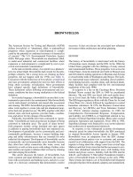
shown in Figure 13.
However, as the thickness of the film
increases, the zone next to the filter medium becomes anaero-
bic. Increased anaerobic activity near the surface may liquify
the film in contact with the medium, resulting in sloughing
or falling down of the old film and growth of a new film.
The sloughed solids are separated in a secondary settling
tank and a part of these may be recirculated in the system.
Two types of trickling filters are recognized, primarily on
the basis of their loading rates and method of operation, as
shown in Table 1. In low-rate trickling filter, the wastewater
passes through only once and the effluent is then settled prior
to disposal. In high-rate trickling filter, wastewater applied
FIGURE 12 Typical wastewater treatment sequence.
Raw
Wastewater
Pretreatment
Primary
Treatment
Secondary
Treatment
(Biological)
Sedimentation
Tertiary
Treatment
Final
Effluent
1. Screening and
Grit Removal
2. Oil Separation
Disposal
Sludge
Digestion
1. Flotation
2. Sedimentation
1. Activated Sludge
2. Trickling Filters
3. Anaerobic Lagoons
4. Aerated Lagoons
5. Stabilization Ponds
6. RBC
MICROBIAL
FILM
WASTE
WATER
NUTRIENTS
OXYGEN
END PRODUCTS
AIR
FILTER
MEDIUM
ANAEROBIC
AEROBIC
FIGURE 13 Process of BOD removal in trickling filters.
© 2006 by Taylor & Francis Group, LLC
BIOLOGICAL TREATMENT OF WASTEWATER 147
to filters is diluted with recirculated flow of treated effluent,
settled effluent, settled sludge, or their mixture, so that it is
passed through the filter more than once. Several recircula-
tion patterns used in high-rate filter systems are shown in
ASCE Manual.
36
Sometimes two filter beds are placed in
series and these are called Two-Stage Filters.
The advantages and disadvantages of recirculation are
listed below:
Advantages of Recirculation
(a) Part of organic matter in influent wastewater is
brought into contact with growth on filter media
more than once.
(b) Recirculated liquid contains active microor-
ganisms not found in sufficient quantity in raw
wastewater, thus providing seed continually. This
continuous seeding with active microorganisms
and enzymes stimulates the hydrolysis and oxi-
dation and increases the rate of biochemical
stabilization.
(c) Diurnal organic load is distributed more uni-
formly. Thus, when plant flow is low, operation is
not shut off. Also, stale wastewater is freshened.
(d) Increased flow improves uniformity of distribu-
tion, increases sloughing and reduces clogging
tendencies.
(e) Higher velocities and continual scouring make con-
ditions less favourable for growth of filter flies.
(f) Provides for more flexibility of operation.
Disadvantages
(a) There is increased operating cost because of
pumping. Larger settling tanks in some designs
may increase capital cost.
(b) Temperature is reduced as a result of number of
passes of liquid. In cold weather, this results in
decreased biochemical activity.
(c) Amount of sludge solids to digesters may be
increased.
The ACE Manual
36
lists the following factors affecting
the design and operation of filters:
(a) composition and characteristics of the wastewater
after pretreatment,
(b) hydraulic loading applied to the filter,
(c) organic loading applied to the filter,
(d) recirculation, system, ratio and arrangement,
(e) filter beds, their volume, depth and air ventilation,
(f) size and characteristics of media, and
(g) temperature of wastewater.
Assuming that the flow through the packed column could be
approximated as plug flow, and if BOD removal rate occurs
by first order reaction, Eq. 13, then the formula to use in
trickling filters will become:
d
d
S
t
qSX k S
f
ϭ =
or
S
S
e
kt
f
0
ϭ
Ϫ
e.
(21)
Another equation suggested for application in trickling fil-
ters
13
is:
S
SqXtk
t
e
f0
1
1
1
1
ϭ
ϩ
ϭ
ϩ
(22)
where trickling filter rate coefficient, k
f
, is a function of
active film mass per unit volume and remains constant for a
given specific area and uniform slime layer. Contact time, t,
TABLE 1
Comparison of low-rate and high-rate filters
Parameters Low-Rate Filters High-Rate Filters
Hydraulic Loading
US gallons per day per square foot 25 to 100 200 to 1000
Million US gallons per day per acre 1.1 to 4.4 8.7 to 44
Cubic metre per day per square metre 1.0 to 4.1 8.1 to 40.7
Organic Loading (BOD)
Pounds of BOD per day per 1000 cubic feet 5 to 25 25 to 300
Pounds of BOD per day per acre-foot 220 to 1100 1100 to 13000
g of BOD per day per cubic metre 80 to 400 400 to 4800
Recirculation Generally absent Always provided R = 0.5 to 3
Effluent Quality High nitrified, lower BOD Not fully nitrified, higher BOD
© 2006 by Taylor & Francis Group, LLC
148 BIOLOGICAL TREATMENT OF WASTEWATER
is related to filter depth, H , volumetric rate of flow per unit
area, Q
a
, and specific surface area of filter media, A
v
. Sinkoff,
Porges, and McDermott
37
have proposed the following rela-
tionship based on their experiments:
tcH
A
Q
v
a
n
ϭ
1
⎡
⎣
⎢
⎤
⎦
⎥
(23)
c
1
is assumed to be a constant and exponent n ranges between
0.53 and 0.83 depending upon the type of filter medium and
the hydraulic characteristics of the system. Substitution of
this value of t in Eq. 21 gives:
S
S
k
A
Q
Hc
e
f
v
a
n
kHQ
fa
n
0
1
ϭϪ ϭ
Ϫ
exp
.
⎡
⎣
⎢
⎤
⎦
⎥
e
Јր
(24)
Eckenfelder
13
suggests that the amount of active surface
film covering the filter medium decreases with depth H;
therefore, combining Eqs. 22 and 23 and substituting c
1
ϰ 1/ H
m
,
gives:
S
S
kAHmQ kHmQ
e
fv
n
a
n
fa
n
0
1
11
1
11
ϭ
ϩϪ
ϭ
ϩϪ
(
)
(
)
րր
Љ
.
(25)
For treatment of domestic wastewater on rock filters,
Eckenfelder has obtained the values of n = 0.5, m = 0.33 and
k
Љ
f
= 2.5 with H in ft and q in MGD/acre. Several empirical
relationships for process efficiency in trickling filters have
been proposed and successfully applied. Most significant
of these are the National Research Council Formula and
Rankin’s Formula which have been described in detail in
ASCE Manual.
36
Eckenfelder and O’Connor
13
have reported
a value of 1.035 for overall temperature coefficient, u, in
Eq. 16. An adjustment in process efficiency due to variation
in temperature should be provided.
Activated Sludge Process
It is a biological treatment process in which biologically
active mass, called activated sludge, is continuously mixed
with the biodegradable matter in an aeration basin in the
presence of oxygen. The combination of wastewater and
activated sludge is called the mixed liquor. The oxygen
is supplied to the mixed liquor either by diffusing com-
pressed air or pure oxygen into the liquid or by mechanical
aeration. The activated sludge is subsequently separated
from the mixed liquor by sedimentation in a clarifier and
a part of this sludge is recirculated to the aeration basin.
The rest of this sludge, indicating net excess production of
biological cell material, is disposed of. Activated sludge
treatment plants vary in performance due to variation in
unit arrangements, methods of introducing air and waste-
water into the aeration basin, aeration time, concentration
of active biomass, aerator volume, degree of mixing, etc.
Some important types of activated sludge processes are
discussed below and their operating parameters are sum-
marized in Table 2.
TABLE 2
Activated sludge process parameters
Parameters Conventional
Step
Aeration
Short
Term Biosorption
Pure
Oxygen
Complete
Mixing
Extended
Aeration
Aerated
Lagoons
Organic Loading Rate—B
v
1b BOD
5
per day per 1000
cubic feet
30–40 50–150 100–400 30–70 150–250 125–180 10–20 5
g BOD
5
per day per
cubic metre
480–640 800–2400 1600–6400 480–1120 2400–3200 2000–2880 160–320 80
Process Loading Factor, U
1b BOD
5
per day per 1b
1b MLVSS
or
kg BOD
5
per day per kg
MLVSS
0.2–0.5 0.2–0.5 2–5 0.2–0.5 0.4–1.0 0.6–1.0 0.05–0.2 0.2
Sludge Age, days, θ
x
3–4 3–4 0.2–0.5 3–4 0.8–2.3 14–ϱ 3–5
Aeration Time, hours, t
¯
6–7.5 6–7.5 2–4 0.5–1.5
(aeration)
1–3 3–5 20–30 70–120
BOD
5
removal, %, E 90–95 90–95 60–85 85–90 88–95 85–90 85–90 85–90
Normal Return Sludge
Average Resign Flow
100ϫ
30 (15–75)* 50 (20–75)* 20 (10–50)* 100 (50–150)* 25 (20–50)* 100 (50–150)* 100 (50–200)* 0
Primary Settling Required Yes Yes No Optional Yes Optional No No
*
Provision in design should be made for these maximum and minimum values.
© 2006 by Taylor & Francis Group, LLC
BIOLOGICAL TREATMENT OF WASTEWATER 149
Kinetic Rate: Depending upon the design and operating
conditions, one or more of the kinetic rate Eqs. 10, 12, 13
and 14 for BOD removal can be applied to different types of
the activated sludge processes.
Oxygen Requirement: Oxygen is used to provide energy
for synthesis of biological cells and for endogenous respira-
tion of the biological mass. The total oxygen requirement,
∆ O
2
, can be expressed with the following equation;
∆ O
2
= a Ј∆ S + bЈ X
T
(26)
where a Ј is the fraction of BOD removed that is oxidized for
energy and bЈ is the oxygen used for endogenous respira-
tion of the biological mass, per day. In conventional aera-
tion basins, an hourly oxygen demand of 50 to 80 mg/L per
1000 mg/L of VSS is exerted near the beginning of the tank
and is reduced to 20 mg/L per 1000 mg/L of VSS in the
course of 4 to 6 hours.
14
Excess Sludge Yield: By applying material balance for
volatile suspended solids in activated sludge system, and
using the concept shown in Figure 3:
Excess solids in activated sludge system = Non-
biodegradable suspended solids in influent + Biomass
Synthesized during BOD removal – Biomass broken down
by endo genous respiration
or
⌬ϭϩ⌬ϪXfXaSbX
T0
(27)
where:
∆ X = Net accumulation of volatile suspended solids, g/day
f = Fraction of volatile suspended solids present in the
influent which are non-degradable
X
0
= Influent volatile suspended solids, g/day
Temperature Effect: According to Eckenfelder and
O’Connor,
13
the value of temperature coefficient in Eq. 12
varies between 1.0 for low loading rates to 1.04 for high
loading rates. Friedman and Schroeder
38
have studied in
detail the effect of temperature on growth and the maximum
cell yield occurred at 20°C.
Elements of a conventional activated sludge system are
shown in Figure 14. In this system, the settled waste is mixed
with the return sludge at the inlet end of the aeration tank.
The microorganisms receive the full impact of any shock
load and respond accordingly with sudden increase in oxygen
demand during growth. By the time microorganisms leave the
aeration tank, the organic matter has been stabilized and the
microorganism population starts dying off. Thus, the micro-
bial population undergoes a continual shifting and never
reaches a relatively constant equilibrium.
7
A mass of activated sludge of three to four times the
mass of the daily BOD load must be kept in the system in
order to consume all the new food and also acquire good
settling properties. These types of plants have been used
for treating domestic wastewaters of low biochemical
oxygen demands. In conventional activated sludge plants
BOD ADSORBED AND SYNTHESIZED
BOD OF SETTLED EFFLUENT
SECONDARY
SETTLING
TANK
EFFLUENT
AIR DIFFUSERS
AERATION BASIN
RETURN SLUDGE
SLUDGE
EXCESS SLUDGE
PRIMARY
SETTLING
TANK
INFLOW
SLUDGE DISPOSAL
BOD OF SETTLED MIXED LIQUOR
TIME
BOD OXIDIZED
FIGURE 14 Conventional activated sludge.
© 2006 by Taylor & Francis Group, LLC
150 BIOLOGICAL TREATMENT OF WASTEWATER
that have plug flow design, high BOD in influent causes
higher oxygen demand at that point in the mixed liquor
and this oxygen demand diminishes as the flow passes
down the aeration tank. Most of the plants designed these
days are provided with tapered aeration, with highest air
supply near the inlet end and lowest near the outlet end of
the aeration tank.
Modifications of the Conventional Activated Sludge
Process
A. Step Aeration Activated Sludge
Step aeration process, developed by Gould
39
at New
York City, offers more flexibility than the conventional
activated sludge process. In this process, wastewater
is introduced at four or more points along the aeration
tank in order to maintain a uniformly distributed load-
ing. In addition to evening out the oxygen demand, this
also keeps sludge reaerated in the presence of substrate.
This process remains biologically more active instead
of reaching the endogenous phase near the end of the
conventional aeration tank. Step aeration system layout
and fluctuations in BOD in aeration tank are shown in
Figure 15.
This method has been successfully employed
in the treatment of domestic wastewaters and industrial
wastewaters of similar nature.
B. Short Term Aeration or High Rate or Modifi ed Activated
Sludge
These systems have very high loading rates, both in
terms of organic and volumetric loading, and low mixed
liquor volatile suspended solids, thus requiring small
aeration tank capacities and reduced air requirements.
Because of shorter aeration time and lower mass of
organisms, this process provides an intermediate degree
of treatment. Organic matter is removed largely by syn-
thesis, thus exerting a high rate of oxygen demand and
producing a relatively large volume of sludge per unit
mass of BOD removed. Since the sludge still contains
certain unstabilized organic matter, the settled sludge in
secondary settling tanks should be removed rapidly in
order to avoid its anaerobic decomposition and floata-
tion. The flow diagram is similar to the conventional
system as shown in Figure 14.
C. Contact Stabilization or Biosorption
The elements of this type of plant are shown in
Figure 16. This system is ideally suited to the treat-
ment of wastewaters in which a large portion of BOD is
SECONDARY
SETTLING
TANK
STEP AERATION BASIN
DISTRIBUTED LOADING
RETURN SLUDGE
SLUDGE
EXCESS SLUDGE
PRIMARY
SETTLING
TANK
INFLOW
SLUDGE
DISPOSAL
BOD OF SETTLED MIXED LIQUOR
TIME
FIGURE 15 Step aeration activated sludge.
© 2006 by Taylor & Francis Group, LLC
BIOLOGICAL TREATMENT OF WASTEWATER 151
present in suspended or colloidal form. The suspended
BOD is rapidly absorbed in a short period, ½ to 1½
hours, by the well-activated organisms and a part of
soluble BOD is metabolized. In the activation tank, the
sludge is reaerated for bio-oxidation and stabilization of
adsorbed food; and when returned to the aeration tank,
it is activated for higher BOD removal as compared to
the conventional plant where sludge has become lean
and hungry in the absence of a food supply. The addi-
tional advantage of this process is the reduced overall
tank volume required as compared to the conventional
system. However, the operation of such plants is more
complex and less flexible than conventional ones.
D. Completely Mixed Activated Sludge
“Complex mix” approach is with respect to combining
the return sludge and wastewater in order to maintain the
entire contents of the aeration chamber in essentially a
homogenous state. Wastewater introduced into the aera-
tion basin is dispersed rapidly throughout the mass and is
subjected to immediate attack by fully developed organ-
isms throughout the aeration basin. Biological stability
and efficiency of the aeration basin is enhanced by this
design. Layout of a completely-mixed activated sludge
plant and variation in BOD are shown in Figure 17.
In this mathematical analysis, McKinney
5
considered
the complete mixing activated sludge process as the one
in which the untreated wastes are instantaneously mixed
throughout the aeration tank. In effect, the organic load
on the aeration tank is uniform from one end to the other
end and consequently a uniform oxygen demand and a
uniform biological growth are produced. It is assumed
to reduce the effect of variations in organic loads that
produce shock loads on conventional units, retain a
more biological population and hence, produce a more
uniform effluent, and be able to treat organic wastes of
any concentration and produce an effluent of any desired
concentration.
5
Using Treatment Model II, Figure 11, as
an example of a completely mixed system, Lawrence
and McCarty
11
have shown analytically that although
the complete-mixing will reduce the shock loads due to
variations in organic loads, plug flow type conventional
units, Treatment Model III, are more efficient.
Assuming that Eq. 13 is applicable for BOD removal
rate, and since the BOD in a completely mixed aera-
tor, S, is equal to the effluent BOD, S
e
, therefore under
steady state conditions:
d
d
0
S
t
SS
t
qXS
e
e
=
−
=
or
S
SqXt
e
0
ϭ
ϩ
1
1
.
(28)
SECONDARY
SETTLING
TANK
EFFLUENT
AERATION
(SORPTION)
BASIN-I
ACTIVATION
TANK-II
RETURN SLUDGE
EXCESS SLUDGE
PRIMARY
SETTLING
TANK
INFLOW
SLUDGE DISPOSAL
BOD OF SETTLED MIXED LIQUOR
BOD OF SETTLED MIXED LIQUOR
TIME IN I
TIME IN II
FIGURE 16 Biosorption (contact stabilization) activated sludge.
© 2006 by Taylor & Francis Group, LLC
152 BIOLOGICAL TREATMENT OF WASTEWATER
E. In recent years, several wastewater treatment plants
have been designed to operate with pure oxygen instead
of conventional use of air in activated sludge treatment
process. The obvious advantage of pure oxygen aeration
is the higher oxygen concentration gradient maintained
within the liquid phase, and this condition permits
higher concentration of biomass in the aeration tank.
This process has been shown to be more economical
due to less energy requirements and in some cases has
produced a better quality effl uent. Signifi cant increase
in volumetric loading rate, reduction in sludge produc-
tion, elimination of foaming problems and decrease in
treatment costs are claimed to be advantages.
40
A pure oxygen activated sludge system developed by
Union Carbide Corporation is shown in Figure 18. This
process is operated at MLSS values between 3000–
10000 mg/L and the settling rate of sludge is consider-
ably improved.
F. Extended Aeration
Extended aeration plant is the one where the net
growth rate is made to approach zero, i.e., rate of
growth becomes approximately equal to rate of decay.
This is achieved by increasing the aeration time in order
to keep the sludge in the endogenous growth phase for a
considerable time. In practice, it is impossible to operate
an extended-aeration system without sludge accumula-
tion, because certain volatile solids, mainly polysaccha-
rides in nature and inert organisms in activated sludge
process, accumulate in the plant. Excess sludge is not
generally wasted continuously from an extended aera-
tion, but instead, the mixed liquor is allowed to increase
in suspended solids concentration and a large volume
of the aeration tank content or return sludge is periodi-
cally pumped to disposal. Oxidation ditch plants are
designed and operated on this principle. Layout of a
typical extended-aeration plant and variation in BOD in
aeration tank are shown in Figure 19.
G. Aerated Lagoons
These are similar to the activated sludge system but
without recirculation of sludge. Mechanical or diffused
aeration devices are used for supplying oxygen and also
providing sufficient mixing. All suspended solids may
or may not be kept in suspension, depending upon the
degree of mixing. Deposited solids may undergo anaer-
obic decomposition. Mathematically, the BOD removal
rate in aerated lagoons is given by Eq. 13 and assuming
the aerated lagoon to be a completely mixed system,
without recycle and maintaining sufficient turbulence,
SECONDARY
SETTLING
TANK
EFFLUENT
EFFLUENT
INFLUENT
AERATION BASIN
RETURN
SLUDGE
EXCESS SLUDGE
PRIMARY
SETTLING
TANK
INFLOW
SLUDGE
DISPOSAL
BOD
TIME
FIGURE 17 Complete mixing activated sludge.
© 2006 by Taylor & Francis Group, LLC
BIOLOGICAL TREATMENT OF WASTEWATER 153
this equation becomes similar to Eq. 28. In practice, this
equation has proven to represent a generalized response
function for design of most aerated lagoons.
33
The exact solid level in an aerated lagoon can be
approximated by applying a material balance around
the lagoon, under equilibrium conditions:
Solids In + Net Synthesis In Basin = Solids Out
or
X
0
+ ( Y ∆ S – b X
e
t ) = X
e
or
X
XYS
bt
e
ϭ
ϩ⌬
ϩ
0
1
(29)
Because of a very low solid concentration, the deten-
tion time in aeration basins is very high and a large
volume of aeration basins is required. Therefore, the
temperature variation exerts a profound effect on the
rate of BOD removal. Eckenfelder and Ford
10
have
given a relationship for estimating the lagoon tempera-
ture at both extreme conditions. Once this temperature
is established, a corrected k
T
value should be obtained
from Eq. 16, using u equal to 1.035 and then adopted in
the kinetic Eq. 28.
Several other modifications in the activated sludge
process have been discussed elswhere;
41
but most of these
modifications are similar in concepts to one or more of
the types discussed above. For example, in Hatfield and
Kraus systems the supernatant from digestion tanks or even
digested sludge are added to the reaeration tank to provide
nutrients. Similarly, an Activated Aeration Plant is a com-
bination of a conventional activated sludge process and the
short-term aeration process.
Rotating Biological Contactors
As mentioned earlier, the traditional aerobic biological
wastewater treatment processes have been divided into two
groups: fixed film or stationary contact systems like trickling
filters and suspended contact systems like activated sludge
process. Rotating biological contactors, RBC, are more like
trickling filters in operation, but adopt certain characteristics
of suspended growth systems. In this process, large light-
weight plastic disks of 2–4 m diameter are half submerged
in the wastewater flowing continuously through cylindrical
bottomed tanks. The disks are rotated slowly at a speed of
1–2 rpm. The biomass grows on the plastic disks and the
substrate is absorbed by this biomass while it is submerged
in the wastewater. The oxygen absorption occurs when the
biomass is in direct contact with air, generally at a rate higher
than that obtained in trickling filters.
These units have been operated successfully at extreme
temperature conditions both for municipal and industrial
wastewaters having very high BOD values. Antoine and
Hynek
42
have concluded that RBC are stable, versatile and
competitive with the activated sludge process.
In Canada, an important parameter regulating the pulp
and paper wastewater treatment is toxicity reduction, mea-
sured by rainbow trout standard bioassay tests. The results
of bioassay tests conducted by Antoine
43
showed RBC was
effective in treating the toxic paper mill wastewater, when
RECYCLE
SLUDGE
WASTE
LIQUOR
FEED
OXYGEN
FEED GAS
CONTROL
VALVE
AERATION
TANK COVER
AGITATOR
GAS RECIRCULATION
COMPRESSORS
EXHAUST
GAS
MIXED
LIQUOR
EFFLUENT
TO
CLARIFIE
R
STAGE BAFFLE
FIGURE 18 Schematic diagram of “unox” system with rotating sparger.
© 2006 by Taylor & Francis Group, LLC
it was operated at disk speeds of 13 and 17 rpm and flow
rates of 1.9 to 2.5 LPM (0.5 to 0.65 USGPM). Similarly,
Antoine observed that the RBCs were able to produce
acceptable effluents for boardmill, kraft and sulfite waste-
waters. For sulfite wastewater, the loading rate had to be
reduced to increase the detention time. On the other hand, the
suspended growth treatment of pulp and paper wastes has
not consistently produced effluents of an acceptable level.
B.C. Research had conducted tests on the use of the rotat-
ing biological contactor process for refinery waste contain-
ing phenols and observed it to be an effective method with
proper control on operation.
43
Anaerobic Treatment
In this process, anaerobic bacteria stabilize the organic matter
in absence of free oxygen. Anaerobic treatment has been used
widely for stabilization of sludges collected from primary and
secondary settling tanks and recently is being adopted for treat-
ment of soluble wastes in anaerobic lagoons, anaerobic filters,
etc. One of the important advantages of anaerobic processes
over aerobic processes is a high percentage conversion of
organic matter to gases and liquid and a low percentage conver-
sion to biological cells. McCarty
44
has mentioned that efficient
anaerobic treatment of soluble wastes with BOD concentration
as low as 500 mg/L is now feasible. Wastes with lower BOD
can also be treated anaerobically, although the waste treatment
efficiency will not be of the same magnitude as expected from
aerobic treatment.
Anaerobic treatment of wastewaters takes place in two
stages as shown in Figure 20. In the first stage, complex
organic materials like protein, fats, carbohydrates, are con-
verted into simple organic acids by acid forming bacteria,
but with little change in BOD or COD value. In the second
stage, these fatty acids are converted to carbon dioxide and
methane, thereby stabilizing the BOD or COD.
In a conventional anaerobic treatment process, the sub-
strate is fed into the digester continuously or intermittently. In
most of the existing digesters, the contents are mixed, mechan-
ically or with compressed gas collected from digesters. There
is no recirculation of digested sludge and the system is a typi-
cal flow through system. The hydraulic detention time, t
-
in
BOD OF
SETTLED MIXED LIQUOR
SLUDGE
BOD
BOD
TIME
AERATION BASIN
INFLOW
RETURN SLUDGE - 100%
SLUDGE WASTED
PERIODICALLY
SETTLING
TANK
EFFLUENT
FIGURE 19 Extended aeration activated sludge.
154 BIOLOGICAL TREATMENT OF WASTEWATER
© 2006 by Taylor & Francis Group, LLC
the conventional process becomes equal to the solid retention
time, u
x
. Recently, several modifications have been made in
the conventional anaerobic treatment process. McCarty
44
has
grouped the basic anaerobic process designs into Conventional
Process, Anaerobic Activated Sludge Process, and Anaerobic
Filter Process. Operating conditions of these process designs
are shown in Figure 21. It is suggested that the conventional
process be used for concentrated wastes like sludges where
economical treatment can be obtained by keeping hydraulic
detention time, t
-
equal to the desired solid retention time, u
x
.
The economic treatment of diluted wastes, however, requires
hydraulic detention time, t
-
, much below the desired solid
retention time, u
x
, and thus, anaerobic contact processes
become more applicable.
44
Anaerobic treatment processes are more sensitive to
operating parameters and their environments as compared
to aerobic processes. The best parameter for controlling the
operation of anaerobic treatment is the biological retention
time or solid retention time, SRT. A minimum SRT exists
below which the critical methane producing bacteria are
removed from the system faster than they can reproduce
themselves. In practice, SRT values of two to ten times
this minimum value are used. Thus, the hydraulic deten-
tion time and solid retention time maintained in anaerobic
treatment processes are very high and the net growth of
biological solids becomes very low due to significant decay
as given by Eq. 12.
Mixing of the digester content is becoming a common
practice. The advantages of mixing are better contact
between food and microorganisms, uniform temperature,
reduction in scum formation, accelerated digestion and dis-
tribution of metabolic inhibitors.
Certain cations, such as sodium, potassium, calcium, or
magnesium show a toxic or inhibitory effect on anaerobic
treatment when present in high concentrations, as shown
in Table 3.
45
Soluble sulfides exhibit toxicity because only they are
available to the cells. If the concentration of soluble sulfides
exceeds 200 mg/L, then the metabolic activity of methano-
genic population will be strongly inhibited leading to the
process failure.
21
Concentrations up to 100 mg/L can be toler-
ated without acclimation and sulfide concentrations between
100 and 200 mg/L can be tolerated after acclimation.
CONTACT MEDIA
MIXED
LIQUOR
RETURN
MIXING
MIXING
WASTE ORGANISMS
EFFLUENT (Q
1
L
e
, ∆S/∆T)
EFFLUENT (Q
1
L
e
, ∆S/∆T)
EFFLUENT (Q
1
L
e
)
INFLUENT (Q
1
L
e
)
INFLUENT (Q
1
L
e
)
INFLUENT (Q
1
L
e
)
ANAEROBIC FILTER PROCESS
ANAEROBIC ACTIVATED SLUDGE PROCESS
CONVENTIONAL PROCESS
CH
4
+ CO
2
CH
4
+ CO
2
CH
4
+ CO
2
∆S/∆T
∀, L, S
∀, L, S
1
L
FIGURE 21 Basic anaerobic process designs.
Complex Organic
Material
(Proteins, Fats,
Carbohydrates)
Acid Producing
Methane Producing
Bacteria
Bacterial Cells
CH
4
+ CO
2
+
Matter
Bacteria
Organic Acid
(Acetic Acid,
Propionic Acid, )
+
Bacterial Cells
+
CO
2
+ H
2
O
+ H
2
S + N
2
+ H
2
O + Humus
FIGURE 20 Sequential mechanism of anaerobic waste treatment.
BIOLOGICAL TREATMENT OF WASTEWATER
155
TABLE 3
Stimulatory and inhibitory concentrations of light metal cations to
anaerobic processes
Cation Stimulatory Con., mg/L Strong Inhibitory Con., mg/L
Sodium 100–200 8000
Potassium 200–40 12000
Calcium 100–200 8000
Magnesium 75–150 3000
© 2006 by Taylor & Francis Group, LLC
156 BIOLOGICAL TREATMENT OF WASTEWATER
Depending on pH, ammonia can be toxic to anaerobic
bacteria and free ammonia is more toxic. If concentration
of free ammonia exceeds 150 mg/L, severe toxicity will
result, whereas the concentration of ammonium ions must be
greater than 3000 mg/L to have the same effect. At a concen-
tration of 1600 mg/L as N, ammonia can upset the process.
20
The volatile acids cause little inhibition in anaerobic reac-
tors at neutral pH.
21
Operating parameters of conventional
anaerobic digesters are shown in Table 4.
6. NUTRIENT REMOVAL
Biological nitrification and denitrification is one of the
common methods for nitrogen removal from wastewaters.
In warmer climates, nitrification may occur to a consider-
able degree in conventional aerobic biological treatment
processes, followed by serious adverse effects of denitrifica-
tion in settling tanks and/or the receiving bodies of water. In
northern cold climates, below 18°C, a three-stage biological
system as shown in Figure 22 is considered necessary for
nutrient removal.
46
In the first stage, carbonaceous BOD is
reduced to a level below 50 mg/L. In the second stage, the
ammonia, present in effluent from the first stage, is oxidized
to nitrites and nitrates by nitrosomonas and nitrobacters,
respectively, as shown below:
23 2 2
2
NH O NO H O 4H
NO O
42
Nitrosomonas
22
22
Nitrobacte
ϩϪϩ
Ϫ
ϩϩ
ϩ
⎯→⎯⎯⎯⎯
rr
3
NO⎯→⎯⎯⎯ 2
Ϫ
The third stage accomplished denitrification–conversion of
nitrites and nitrates to atmospheric nitrogen under anaerobic
conditions:
32
2
NO CH OH 3NO CO H O
2NO CH OH N CO H O 2OH
33 222
23 222
ϪϪ
ϪϪ
ϩϩϩ
ϩ ϩϩϩ
→
→
PHOSPHORUS AND BOD REMOVAL
NITRIFICATION
DENITRIFICATION
Coagulating Chemical Application (Optional Points)
Air Air Methanol
Raw
Wastewater
Settling Settling
Settling
Settling
Reaction
Tank
Aeration
Tank
Waste Sludge
Waste Sludge Waste Sludge
Waste Sludge
Return
Sludge
Return
Sludge
Return
Sludge
Effluent
Aeration
Tank
FIGURE 22 Typical three-stage treatment process for nutrient removal.
TABLE 4
Operating parameters of conventional anaerobic digesters
Parameters Unmixed Mixed
B
v
– Loading Rate, 0.02–0.05 0.1–0.3
1b VSS/day/cubic ft
kg VSS/day/cubic metre
0.32–0.80 1.6–3.2
t
¯
– Detention time, days 30–90 10–15
E
– Volatile Solids
Reduction percent
50–70 50
Mixing Absent Present
pH 6.8–7.4 6.8–7.4
Temperature, °C 30–35 30–35
© 2006 by Taylor & Francis Group, LLC
BIOLOGICAL TREATMENT OF WASTEWATER 157
A supplemental source of carbonaceous BOD must be added
in this stage to reduce the nitrates to nitrogen gas in a reason-
able period of time. This has been accomplished either by
adding a cheap organic substrate like methanol or by bypass-
ing a part of the wastewater containing carbonaceous BOD
in the first stage. In some cases, the carbonaceous and nitro-
geneous oxidation steps are combined in a one-stage aerobic
biological system. Another system uses fixed-film reactors,
such as gravel beds, separately for nitrification and denitri-
fication stages. Effluent nitrogen concentrations of 2 mg/L
have been proposed as the upper limit in a biological process.
Many full scale biological nitrogen removal facilities are now
in operation. Nitrifying bacteria are subject to inhibition by
various organic compounds, as well as by inorganic com-
pounds such as ammonia. Free ammonia concentrations of
0.1 to 1.0 mg/L and free nitrous acid concentrations of 0.22 to
2.8 mg/L, start inhibiting Nitrobacters in the process.
20
The majority of phosphorus compounds in wastewaters are
soluble and only a very small fraction is removed by plain sedi-
mentation. The conventional biological treatment methods typ-
ically remove 20 to 40 percent of phosphorus by using it during
cell synthesis. A considerably higher phosphorus removal has
been achieved by modifying the processes to create “luxury
phosphorus uptake.” Factors required for this increased pho-
shorus removal are plug-flow reactor, slightly alkaline pH,
presence of adequate dissolved oxygen, low carbon dioxide
concentration and no active nitrification.
46
However, the most
effective method of phosphate removal is the addition of alum
or ferric salts to conventional activated sludge processes.
Nomenclature
A
v
= Specific surface area of filter media, Length
– 1
B
v
= Volumetric loading rate; mass per unit volume per
unit time
D = Longitudinal dispersion coefficient, (Length)
2
per
unit time
E = Process treatment efficiency, ratio
H = Filter depth, length
K = Half velocity coefficient = substrate concentration
at which rate of its utilization is half the maximum
rate, mass per unit volume
K
i
= Inhibition constant, mass per unit volume
L = Substrate concentration around microorganisms in
reactor, measured in terms of BOD, mass per unit
volume
N
0
= Number of microorganisms per unit volume at
time t = 0
N
t
= N = Number of microorganisms per unit volume at
time t
∆ O
2
= Amount of oxygen requirement, mass per unit time
Q = Volumetric rate of flow, volume per unit time
Q
a
= Volumetric rate of flow per unit area, Length per
unit time
Q
r
= Volumetric rate of return flow, volume per unit
time
R = Recycle ratio
S = Substrate concentration, mass per unit volume
∆ S = Substrate removed, mass per unit time
S
e
= Effluent BOD or final substrate concentration,
mass per unit volume
S
0
= Influent BOD or in the initial substrate concentra-
tion, mass per unit volume
T = Temperature, °C
U = Process loading factor, time
– 1
V = Volume of the reactor, volume
X = Mass of active microorganisms present per unit
volume
∆ X = Cell mass synthesized, mass per unit time
X
e
= Effluent volatile suspended solids, mass per unit
volume
X
0
= Influent volatile suspended solids, mass per unit
volume
X
r
= Volatile suspended solids in return sludge, mass
per unit volume
X
T
= Total mass of microorganisms in the reactor, mass
Y = Growth yield coefficient, dimensionless
a Ј = Fraction of BOD removed that is oxidized for
energy
b = Microorganisms decay coefficient, time
– 1
b Ј = Oxygen used for endogenous respiration of biologi-
cal mass, time
– 1
c
1
= Constant
f = Fraction of volatile suspended solids present in
the influent which are non-degradable
k
f
,kЈ
f
,kЉ
f
= Rate coefficient in filters, time
– 1
k
0
= Logarithmic growth rate constant, time
– 1
k
t
= Growth rate factor, time
– 1
k Ј = Growth rate factor, (time)
– 1
(mass per unit volume)
– 1
l = Length dimension in reactor, Length
m = Constant
n = Trickling filter exponent
q = d S / X d t = Substrate utilization rate per unit biomass
q
max
= Maximum substrate utilization rate per unit
biomass
t = Contact time in filter or any other reactor, time
t
-
= V / Q = Mean retention time, time
u = Mean displacement velocity in reactor along
length, length per unit time
w = Volumetric rate of flow of waste sludge, volume
per unit time
u = Temperature coefficient for microbial activity
© 2006 by Taylor & Francis Group, LLC
158 BIOLOGICAL TREATMENT OF WASTEWATER
u
x
= Mean cell retention time, time
m = dx / X d t = Specific growth rate of microorganisms,
time
– 1
m
max
= Maximum specific growth rate of microorgan-
isms, time
– 1
D / ul = Reactor dispersion number, dimensionless
M / F = Microorganisms to food ratio in a reactor
d L /d t = Rate of waste utilization measured in terms of
BOD, mass per unit volume per unit time
d N /d t = Rate of growth in number of microorganisms,
Number per unit volume per unit time
d S /d t = Rate of substrate consumption, mass per unit
volume per unit time
∆ S / ∆ t = Mass of substrate utilized over one day, mass per
unit time
S
T
/ ∆ t = Total mass of substrate applied over a period of
one day, mass per unit time
d X /d t = Rate of growth of mass of active microorganisms,
mass per unit volume per unit time
∆ X
T
/ ∆ t = Total quantity of active biomass withdrawn daily,
mass per unit time
REFERENCES
1. MacInnis, C., Municipal Wastewater, Encyclopedia of Environmen-
tal Science and Engineering, Vol. 1, edited by J. R. Pfafflin and E.N.
Ziegler, Gordon and Breach, New York.
2. Gates, W.E. and S. Ghosh, Biokinetic Evaluation of BOD Concepts
of Data, Journal of the Sanitary Engineering Division, Proceedings of
the American Society of Civil Engineers, Vol. 97, no. SA3, June 1971,
pp. 287–309.
3. McKinney, R.E., Microbiology for Sanitary Engineers, McGraw-Hill
Book Company, Inc., New York, 1962.
4. Stanier, R.Y., M. Doudoroff and E.A. Adelberg, The Microbial World,
Prentice-Hall, Inc., Englewood Cliffs, NJ, 1957.
5. McKinney, R. E., Mathematics of Complete Mixing Activated Sludge,
Journal of the Sanitary Engineering Division, Proceedings of the
American Society of Civil Engineers, 88, SA3, May 1962, pp. 87–113.
6. Tsuchiya, H.M., A.G. Frederickson and R. Avis, Dynamics of Microbial
Cell Populations, Advances in Chemical Engineering, Vol. 6, edited by
T.B. Drew, J.W. Hoopes, Jr. and T. Vermeulen, Academic Press, New
York, 1966.
7. Stewart, M.J., Activated Sludge System Variations, Specific Applica-
tions, Proceedings of the Fifteenth Ontario Industrial Waste Conference,
June 1968, pp. 93–115.
8. Irvine, R.L. and D.J. Schaezler, Kinetic Analysis of Date from Biologi-
cal Systems, Journal of the Sanitary Engineering Division, Proceedings
of the American Society of Civil Engineers, Vol. 97, No. SA4, August
1971, pp. 409–424.
9. Monod, J., The Growth of Bacterial Cultures, Annual Review of Micro-
biology, 3, 371, 1949.
10. Eckenfelder, W.W. and D.L. Ford, Water Pollution Control, Jenkins
Publishing Company, Austin, Texas, 1970.
11. Lawrence, A.W. and P.L. McCarty, Unified Basis for Biological
Treatment Design and Operation, Journal of the Sanitary Engineering
Division, Proceedings of the American Society of Civil Engineers,
96, SA3, June 1970, pp. 757–778.
12. Pearson, E. A., Kinetics of Biological Treatment, Advances in Water
Quality Improvement, edited by E.F. Gloyne and W.W. Eckenfelder, Jr.,
University of Texas Press, Austin, 1970.
13. Eckenfelder, W.W. and D.J. O’Connor, Biological Waste Treatment,
Pergamon Press, New York, 1961.
14. Fair, G.M., J.C. Geyer and D.A. Okun, Water and Wastewater Engi-
neering, Vol. 2, John Wiley and Sons, Inc., 1968.
15. Bewtra, J.K., Droste, R.L. and Ali, H.I., The Significance of Power
Input in the Testing and Biological Treatment of Industrial Wastewater,
Treatment and Disposal of Liquid and Solid Industrial Wastes, edited
by K. Curi, Pergamon Press, New York, 1980, pp. 23–47.
16. Ruchhoft, C.C., Studies of Sewage Purification-IX, Public Health
Reports, 54, 468, 1939.
17. Goodman, B.L. and A.J. Englande, Jr., A Unified Model of the Activated
Sludge Process, Journal of the Water Pollution Control Federation, 46,
February 1974, p. 312.
18. Parker, H.W., Wastewater Systems Engineering, Prentice-Hall Inc.,
Englewood Cliffs, 1975.
19. Warren, C.E.,
Biology and Water Pollution Control, W.B. Saunders
Company, Toronto, 1971.
20. Eckenfelder, W.W., Jr., Principles of Water Quality Management, CBI
Publishing Company, Inc., Boston, 1980.
21. Grady, C.P., Jr. and H.C. Lim, Biological Wastewater Treatment —
Theory and Applications, Marcel Dekker, Inc., New York, 1980.
22. Bewtra, J.K., Biological Treatment of Wastewater, Encyclopedia of
Environmental Science and Technology, Vol. I, edited by E. Ziegler
and J. Pfafflin, Gordon and Breach Science Publishers Inc., New York,
1982, pp. 81–102.
23. Bewtra, J.K., Toxocity Effects on Biological Processes in Waste Treat-
ment, New Directions and Research in Waste Treatment and Residual
Management, Vol. 2, Proceedings of International Conference held
at the University of British Columbia, Vancouver, B.C., June 1985,
pp. 807–827.
24. Gaudy, A.F., Jr., W. Lowe, A. Rozich and R. Colvin, Practical Method-
ology for Predicting Critical Operating Range of Biological Systems
Treating Inhibitory Substrates, Water Pollution Control Federation
Journal, Vol. 60, No. 1, 1988, pp. 77–85.
25. Grady, C.P.L., Jr., Biodegradation of Hazardous Wastes by Conventional
Biological Treatment, Hazardous Wastes and Hazardous Materials, 3,
1986, pp. 333–365.
26. Gaudy, A.F., Jr., A.F. Rozick and E.T. Gaudy, Activated Sludge Process
Models for Treatment of Toxic and Nontoxic Wastes, Water Science
and Technology, Vol. 18, 1986, pp. 123–137.
27. Godrej, A.N. and J.H. Sherrard, Kinetics and Stoichiometry of Acti-
vated Sludge Treatment of a Toxic Organic Wastewater, Water Pollu-
tion Control Federation Journal, Vol. 60, No. 2, 1988, pp. 221–226.
28. Pitter, P., Determination of Biological Degradability of Organic Sub-
stances, Water Research, 10, 1976, pp. 231.
29. Adam, C.E., D.L. Ford and W.W. Eckenfelder, Jr., Development of
Design and Operational Criteria for Wastewater Treatment, Enviro
Press, Inc., Nashville, 1981.
30. Pierce, G.E., Potential Role of Genetically Engineered Microorganisms
to Degrade Toxic Chlorinated Hydrocarbons, Detoxication of Hazard-
ous Wastes, edited by J.H. Exner, Ann Arbor Science Publishers, Ann
Arbor, 1982, pp. 315–322.
31. Levenspiel, O., Chemical Reaction Engineering, John Wiley and Sons,
Inc., New York, 1967.
32. Murphy, K.L. and B.I. Boyko, Longitudinal Mixing in Spiral Flow Aer-
ation Tanks, Journal of the Sanitary Engineering Division, Proceed-
ings of the American Society of Civil Engineers, 96, SA2, April 1970,
pp. 211–221.
33. Parker, C.E., Anaerobic – Aerobic Lagoon Treatment for Vegetable Tan-
ning Wastes, Report prepared for the Federal Water Quality Admin-
istration Environmental Protection Agency, U.S. Government Printing
Office, Washington, D.C., December 1970.
34. Stevens, D.K., Interaction of Mass Transfer and Inhibition in Bio-
films, Journal of Environmental Engineering, Vol. 114, No. 6, 1988,
pp. 1352–1358.
35. Toda, K. and H. Ohtake, Comparative Study on Performance of Biofilm
Reactors for Waste Treatment, Journal of General Applied Microbiol-
ogy, Vol. 31, No. 2, 1985, pp. 177–186.
36. Wastewater Treatment Plant Design, American Chemical Society of
Civil Engineers Manual of Engineering Practice, No. 36, New York,
NY, 1977.
37. Sinkoff, M.D., R. Porges and J.H. McDermott, Mean Residence Time
of a Liquid in a Trickling Filter, Journal of the Sanitary Engineering
© 2006 by Taylor & Francis Group, LLC
BIOLOGICAL TREATMENT OF WASTEWATER 159
Division, Proceedings of the American Society of Civil Engineers, 85,
SA6, 1959.
38. Friedman, A.A. and E.D. Schroeder, Temperature Effects on Growth
and Yield for Activated Sludge, presented at 26th Purdue Industrial
Waste Conference, Lafayette, Indiana, May 4–6, 1971.
39. Gould, R.H., Tallmans Island Works Opens for World’s Fair, Municipal
Sanitation, Vol. 10, No. 4, April 1939, p. 185.
40. McWhirter, J.R., Oxygen and the Activated Sludge Process, Chapter 3 in
The Use of High Purity Oxygen in the Activated Sludge Process, Vol. 1
edited by J.R. McWhirter, CRC Press Inc., West Palm Beach, 1978.
41. Srinda, R.T. and R.F. Ward, Activated Sludge Processes: Conventional
Processes and Modifications-Applications, presented at Short Course
in Water Quality Control, Department of Civil Engineering, University
of Massachusetts, Amherst, Mass., March 1970.
42. Antoine, R.L. and R.J. Hynek, Operating Experience with Bio Surf Pro-
cess Treatment of Food Processing Wastes, Proceedings of 28th Industrial
Wastes Conference, Purdue University, Lafayette, Indiana, May 1973.
43. Antoine, R.L. Fixed Biological Surfaces—Wastewater Treatment, CRC
Press, Cleveland, Ohio, 1976, pp. 93–122.
44. McCarty, P.L., Anaerobic Treatment of Soluble Wastes, Advances in
Water Quality Improvement, edited by E. F. Gloyne and W. W. Ecken-
felder, Jr., University of Texas Press, Austin, 1970, pp. 336–352.
45. McCarty, P.L., Anaerobic Waste Treatment Fundamentals, Public
Works, Vol. 95, No. 9–12, 1964, pp. 95–126.
46. Bouck, D.W., Nutrient Removal in Three-Stage Processing, Chapter 5
in Advances in Water and Wastewater Treatment — Biological Nutrient
Removal, edited by M.P. Wanielista and W.W. Eckenfelder, Jr., Ann
Arbor Science, Ann Arbor, MI, 1978, pp. 65–78
J.K. BEWTRA
N. BISWAS
University of Windsor
© 2006 by Taylor & Francis Group, LLC