ENCYCLOPEDIA OF ENVIRONMENTAL SCIENCE AND ENGINEERING - DESALINATION ppsx
Bạn đang xem bản rút gọn của tài liệu. Xem và tải ngay bản đầy đủ của tài liệu tại đây (906.08 KB, 30 trang )
194
D
DESALINATION
INTRODUCTION
Our planet, the earth or gaia, is a water place. Water occu-
pies 70% of the total earth’s area, about 360 ϫ 10
12
m
2
,
and the total water volume that covers the earth’s surface
is about 1.40 ϫ 10
18
m
3
. This makes the planet earth a
very large water reservoir, nevertheless practically, these
huge amounts of water are not directly usable, as 97% of
this water is the seawater of the open seas and oceans and
only 3% consist of fresh and brackish water, i.e., 0.042 ϫ
10
18
m
3
. From these 3.0% fresh water reserves only a por-
tion (0.014%) is in liquid form in rivers, lakes and wells
directly available to us for immediate use, the rest can be
found as glacier, icebergs and very deep water of geological
reservoirs.
Fresh water, for all of historical times has been an uncon-
trollable happening of nature wherever and however found.
In the Bible “good land” is described as one “of brooks of
water, of fountains, and depths that spring out of valleys and
hills,” for water is a precious source of development and civ-
ilization, because water and civilization are two inseparable
conceptions.
From antiquity up to our times, rivers, seas, oases, and
oceans have attracted man to their shores. As a rule, towns
and countries have grown along rivers. Egypt for example
was considered as “the gift of the river.” Egypt is a typical
historical example of the influence of water to the birth and
development of a civilization.
As a largely developed agricultural country, Egypt was
able to master the river and had most of the time such an
abundant harvest, that it became the main wheat-exporting
country in the whole Mediterranean. The Egyptians learned
to determine the seasons of the year by the behaviour of the
river. Inundation, Emergence of the fields and Drought were
their seasons. The first calendar was created in this way and
out of this was derived the modern calendar.
Unfortunately, fresh water, and even seawater has not
had our proper attention, respect and treatment. Due to the
increase of population, especially in certain regions, and
the increase of living standards, water demand increased
exponentially, and wells or other fresh water sources run dry.
The great population increase multiplies the total withdrawal.
In some areas twice or more as much water is being drawn
out of the ground as sank into it, thus the water table drops
every year a few meters and water shortage increases dra-
matically, especially in dry years.
In modern large civic centers, opening of the tap pro-
vides us with as much fresh water as we are able to waste.
The notion of lack of water is usually a matter we very
seldom think of. However, at the same time there are places
where water is so scarce that there are serious problems of
existence, as is the case these days in many places in Africa.
Generally it is not realized that fresh water represents only
3% of the total reserves in the world and that 75% of it is
immobilized as ice. Modern agriculture also requires con-
siderable amounts of good water to meet increasing food
requirements. There is a tremendous requirement of water to
run industrial plants, to produce all kinds of goods but also
all kinds of polluting effluent.
The quantity of water used varies from location to loca-
tion throughout the day and throughout the year, as many
factors influence this variation. The more important factors
include the economics of a community, its geographic loca-
tion, and the nearby availability of the water source or the
transportation distance from the source.
Climate is the most common cause of water lack or of
water insufficiency. Sparse rainfall to feed streams, wells
and the soil for agricultural production of crops exhausts
water reserves. The most arid areas are the deserts, where
no rain exists and some underground waters most of the time
are salty or brackish. About 19% of the total land surface
of the earth on all continents but Europe, is covered by des-
erts, which are surrounded by semi-arid lands where existing
water is insufficient.
Coastal deserts, where the lack of water is as high as
in the interior deserts, cover about 33,000 km
2
around the
world, the greatest part of which is found in the Middle East,
along the Persian Gulf, adjoining parts of the Arabian Sea
and the Indian Ocean. The coastal deserts are divided into
four main categories, according to their climatic conditions.
© 2006 by Taylor & Francis Group, LLC
DESALINATION 195
The tropical regions, where the temperature is about 30ЊC
in summer and 22ЊC during winter. The subtropical regions,
where in warm periods the temperature is about 30ЊC, and it
ranges between 10 and 22ЊC in the cold months. The regions,
as in the Mediterranean coasts, where during warm periods
the temperatures are 22 to 33ЊC, and in cold months 10 to
22ЊC. The cool coastal deserts have in summer temperatures
under 22ЊC and in winter time 10 to 22ЊC. The last desert
regions are the cold places where summer is under 22ЊC and
winter under 10ЊC. The largest single coastal desert of the
third type, with the moderate climatic conditions, is that of
the Mediterranean Sea and covers about 2650 km
2
.
1
Coastal deserts have an advantage over the interior
deserts. They are climatically more pleasant, because they are
cooler in summer and warmer in winter. Further, they have
advantages over the interior deserts from the desalination
point of view. Coastal deserts are surrounded by abundant
sea water supply which is in the same level as the desalt-
ing installation, and thus the intake of water can be pumped
with less power consumption than the deep well salty or
brackish waters of the inland deserts. The brine disposal is
also easy, without problems, as it is discharged directly into
the sea, whereas the disposal of brine in inland deserts may
create serious problems. Also, coastal deserts are in favour
over the inland ones concurring the transportation of the
equipment and all other necessary supplies for a desalina-
Saudi Arabia.
Some of the most attractive areas and beaches of the
world are almost devoid of water. Not only is this living
space, and space for resort hotels lost, but, in some cases,
profitable resources cannot be exploited. Thus, known min-
erals on Egypt’s Red Sea coast cannot be mined, and fish-
ing industries on South America’s Pacific coast, and other
places around the world, cannot be expanded for lack of
water. These present major losses in the world supplies of
minerals and foods.
WATER DEMAND AND USAGE
The water cycle leaves about 9000 km
3
of water worldwide
per year. This amount is enough to provide, with good qual-
ity water, about 20 billion people, but this water is far from
evenly divided, with major shortages in some regions and
abundant quantities in other places.
In a modern urban agglomeration, supply of water may
satisfy domestic, municipal and industrial demand, as well
as agricultural needs. There are no standards of general
acceptance for the quality of water required by each group
of users. Domestic demand includes all water consumed in
housekeeping and gardening. A limit of 500 mg/L (ppm) for
total dissolved solids with a maximum of 250 mg/L for chlo-
ride and sulphate ions, respectively, is recommended by the
World Health Organization (WHO).
2
Nevertheless, there is
a large number of communities, which are still consuming
water containing up to 1000 mg/L total dissolved solids and
sometimes more. Physiological changes may result from the
intake of large amounts of the main ions, as well as of some
trace elements.
Municipal requirements, beside the supply of water for
domestic use, include all water needed by offices, public and
commercial establishments, fire-fighting and irrigation of
municipal parks. Although the standards for the latter uses
are not strictly the same, as for drinking water, in practice
all municipal water requirements are identical to drinking
water since it is nearly always supplied by the same piping
system.
A large variety of quality standards is involved in the
use of industrial water, depending on its specific use. They
may vary from high-quality drinking water for food process-
ing to completely demineralized water for specific uses.
Limitations of salt content may be imposed in some cases for
process water. Boiler feed water needs special treatment to
minimize salt content and eliminate dissolved gases. Cooling
water also needs some treatment to meet the process require-
ments. River water and sea water can be used for cooling
purposes and this is the usual practice in plants located on a
river or near the seashore.
About 70% of water withdrawn from the earth goes for
agriculture purposes and the balance, 30%, for various uses,
as household and industrial process water. Overirrigation the
last years, brought salinization of the nearby water resources,
affecting the soil and crop quality, as salts are accumulating
in the soil.
Irrigation water quality, which includes also drinking
water for animals, depends to a large extent on the nature of the
soil, the crops and the climate. The yield and quantity of some
crops can be affected, not only by the total amount of dissolved
solids, but also by the presence of certain specific salts. Thus if
desalinated water is to be used in certain places the make-up of
the product water will be necessary.
The water withdrawn per year and per capita, concern-
ing industry and agriculture is increasing by 8.5%, the main
increase in the developed countries. The USA consumes
2500 m
3
per year per capita, Switzerland 500 and Ghana,
a very poor African country, only 40 m
3
.
3
Meanwhile, the majority of fresh water streams are
severely polluted, decreasing the quality water reserves. Self
decontamination is not feasible in many cases and, thus,
treatment methods have to be applied to degrade at least
some of the pollutants in the water. On the other hand, sea
water exist in huge amounts, given free. Although also pol-
luted to some extent, it is a future source of fresh water as
desalination is the future process to produce this valuable
good quality water.
SEA WATER
The seas and oceans are great sources of material available
to mankind, though their destiny is very low to be exploited,
but high enough to make the water salty, unsuitable for drink-
ing or processing purposes. Not all the seas around the world
have the same amount of total dissolved solids, the amount
of which range from 20,000 to 50,000 ppm.
© 2006 by Taylor & Francis Group, LLC
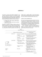
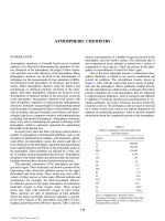
tion plant. Figure 1 shows a modern desalination plant in
196 DESALINATION
and closed seas. Over seventy elements have been detected
in seawater, some in very small to trace amounts. Their pro-
portion in all oceans, independent of their concentration, is
almost stable.
4
The four main metals—sodium, magnesium, calcium
and potassium—and their combining ions, chlorides, includ-
ing the other halogens and bicarbonates, are presented in
major and the minor elements in seawater.
FIGURE 1 Panoramic view of the Al-Jubail Saudi Arabia, phase II, MSF desalination plant. It is up to now the World
largest desalination installation totaling a capacity of 947,000 m
3
/d (250 Mgd) fresh water production. Each unit has a
capacity of 23,500 m
3
/d (6.2 Mgd). The plant was built for the Saline Water Conversion Corporation, of Saudi Arabia
by the Japanese Companies of Sasakura and Mitsubishi. (Courtesy Sasakura Engineering Co., Japan)
© 2006 by Taylor & Francis Group, LLC
amounts beyond comprehension. In Table 2 are given the
T able 1 gives the total dissolved salt of various oceans
DESALINATION 197
Desalination eliminates the main elements from sea-
water, producing fresh water and concentrated brine,
almost saturated in the main salts, which are withdrawn to
the sea. There are two main reasons that these salts are not
exploited. The brine volumes are huge and cannot be han-
dled easily. The present extraction technology is expensive
for the relatively cheap materials. Nevertheless, there is
some industry exploiting, in part, the concentrated brine.
Today throughout the world more than 1,900,000 m
3
/d
(500 MUSGPO) of fresh water is produced by the various
desalination processes.
5
Usually twice to 2½ as much sea-
water is processed, so that the solids concentration of the
brine is doubled. It is estimated that the recovery from the
withdrawn brine can be:
Magnesium 2,306.000 t/y Bromine 116.100 t/y
Calcium 728.000 t/y Copper 5.385 t/y
Potassium 659.000 t/y Uranium 5.385 t/y
Sulfate 4,855.000 t/y Gold 7.2 kg/y
Calcium and magnesium are the main elements that cause
scale formation. Scales are formed and precipitate inside
desalination equipment simultaneously with other suspended
solids content in the feed water sea or brackish. These materi-
als precipitate in areas favored for deposition. In distillation
plants these are the heat exchangers and, in reverse osmosis,
the semipermeable membranes, cause the problems. These
deposits are categorised in two main types, the sludge which
is soft and can be easily washed out, and the scale which is
hard, adheres to heat transfer surfaces and can be removed
only by plant shutdown.
Brackish waters are classified as waters with total dis-
solved solids content ranging from 3,000 ppm to 20,000 ppm.
The elements vary widely, depending on the rocks and soil
coming in contact with the water. In some brackish waters
large amounts of calcium sulfate are present up to satura-
tion conditions, making the water bitter and unsuitable for
any use.
DESALINATION PROCESSES
When all other possibilities to use existing natural water
resources are exhausted or to augment fresh water supply
by conventional methods fail, then desalting of seawater, or
brackish water and/or of polluted water reserves might give
the answer to local water problems. The cost of desalting has
been drastically reduced over the past several years. This is
TABLE 1
Total Dissolved Solids in Various Seas
Ocean/Sea g/kg ppm Ocean/Sea g/kg ppm
Baltic Sea 7.0 7,000 Pacific Ocean 33.6 33,600
Caspian Sea 13.5 13,500 Atlantic Ocean 36.0 33,600
Black Sea 20.0 20,000 Mediterranean Sea 39.0 39,000
White Sea 28.0 28,000 Red Sea 43.0 43,000
Northern Adriatic 29.0 29,000 Kara Bogar (Caspian) 164.0 164,000
Dead Sea 270.0 270,000
TABLE 2
Ionic Composition of Main Elements in Seawater
6
Ions g/kg Ions g/kg
Chlorides Cl
−
18.980 Copper Cu 0.003 × 10
−3
Sodium Na
+
10.560 Uranium U 0.003 × 10
−3
Sulfates SO
2−
4
2.560
Magnesium Mg
2+
1.270 Total TDS — 34.482
Calcium Ca
2+
0.400 Water H
2
O 965.518
Potassium K
+
0.380
Hydrogen Seawater characteristics
Carbonates HCO
3
0.143 Salinity g/kg 34,330
Bromides Br
−
0.065 Chlorinity g/kg 19,000
Boric acid H
3
BO
3
0.026 Chlorocity g/kg 19,950
Strondium Sr
2+
0.014 Specific weight N/m
3
10,243
Fluorides F 0.001
© 2006 by Taylor & Francis Group, LLC
198 DESALINATION
the result of the combined effort of scientists and engineers.
However, it should not be forgotten that desalted water is an
industrial product and its cost can never compete with the
cost of natural fresh water supplies.
The largest desalination plant is Nature. The hydrological
cycle on earth begins by desalination of surface waters. As
the sun’s energy evaporates the water from the oceans and the
land surface waters, the vapors condense again on the earth’s
surface, as desalted water, stored as snow, ice or through the
soil returns to the rivers and seas. This water is the vital liquid
for all creatures on the earth.
The importance of water, as a matter of life, is quoted as
far back as there are records in history. We read in the Old
Testament: “Moses brought the sons of Israel from the Red
Sea and they went into the desert of Shur. They marched three
days in the wilderness and could not find water to drink. And
when they arrived to Merra they could not drink the waters
of Merra, for they were bitter. Therefore, he named this place
‘bitterness.’ And the people murmured against Moses, saying:
What shall we drink? And Moses cried onto the Lord. And
the Lord sweded a wood, which when he had cast into the
waters, the waters were made sweet.”
7
Nobody has guessed
what kind of wood this could be, but is the first known in his-
tory, technical desalination.
The effort of a desalination process is to separate one
of the most common, and most useful and yet most unusual
material—the water from the one of the next common mate-
rial, the salt. Hundreds of processes have been proposed,
based on the various properties of water and its saline solu-
tions. Nevertheless only a few of these methods have reached
such an advanced state of technology to be considered as safe
processes for the commercial conversion of saline waters
into fresh. Distillation processes, reverse osmosis and elec-
trodialysis or in some cases combination of two processes.
The expectations, connected with freezing processes, could
not be met with current freezing technology in large scale
industrial application.
The required separation may be of water from salt, or of
salt from water. Thus the desalination processes can be classi-
fied, according to the operation reference parameter as follow:
1: Methods that separate water from salts
1.1: All distillation methods
1.2: Reverse osmosis
1.3: Crystallization (freezing and hydrates)
2: Methods that separate the salts from the water
2.1: Electrodialysis
2.2: Ion-exchange
2.3: Piezodialysis
2.4: Osmionic methods
3: Methods with phase change
3.1: All distillation methods
3.2: Crystallization
4: Methods without phase change
4.1: Reverse osmosis
4.2: Electrodialysis
From the energy point of view, the methods are classi-
fied as follow:
5: Methods using heat (thermal methods)
5.1: All distillation methods except mechanical
vapor compression
6: Methods using mechanical energy
6.1: Mechanical vapor compression
6.2: Reverse-osmosis
7: Methods using electrical energy
7.1: Electrodialysis
8: Methods depending on chemical energy
8.1: Ion-exchange
The methods which found practical applications in large
scale industrial plants are:
Distillation methods: which comprise the following
modifications:
1: Multiple-Effect Evaporation ME
2: Multi-Stage-Flash Evaporation MSF
3: Vapor-Compression methods VC
4: Solar distillation method SD
Distillation is the most developed process of removing
water from a saline solution. It is applied up to very large
capacities with various types of evaporators and accounts for
about 59.4% of the total world plant capacity.
5
The latent heat of changing phase is an important
factor in the overall process economics, but the degree of
salinity of the raw water is of no importance. Multistage
flash distillation and multi-effect evaporation are reduc-
ing considerably the economic effect of the latent heat of
vaporization.
Reverse osmosis uses mechanical energy, as pres-
sure, to drive the water out of the solution through semi-
permeable membranes. The applied pressure must be higher
than osmotic pressure, its value depending from the salt
content of the brackish or seawater solution. The necessary
counterpressure in reverse osmosis depends greatly upon
the salt content of the raw water and imposes constraints
on membrane life and performance, but also varying energy
consumption according to the salinity of the raw water.
Membrane life is an important cost factor.
Today reverse osmosis plants account, worldwide, for
32.6% for plants having a capacity 100 to 4000 m
3
/d and
19.5% for capacities over 4000 m
3
/d.
Electrodialysis is the most developed process for
eliminating salts from aqueous solutions. The economics
depend closely on the salt content of the raw water, as the
consumption of electric energy is related to the total dis-
solved solids removed from the solution. Electrodialysis
may, therefore, preferably be applied for the purification of
brackish waters. Reversal electrodialysis is a modification,
by which poles are reversing every 20Ј and which assures
the production of high-quality water and minimizes the
rejection of brine.
© 2006 by Taylor & Francis Group, LLC
DESALINATION 199
Today electrodialysis accounts for 5.7% of plants with
capacities 100 to 4000 m
3
/d and 2.5% for capacities over
4000 m
3
/d.
Freezing processes found no commercial application
though the simplicity of the method. They failed because the
size of produced ice was very small and half of the fresh
water was used to wash out the salt from ice surface, render-
ing the method uneconomical.
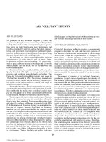
Independently from the method or procedure for sea or
brackish water desalination the operation of a desalination
plant includes some general steps to be followed. Figure 2
gives the procedures before and after the main desalina-
tion step.
ENERGY SOURCES
Running a desalination plant many expenses arise, the high-
est of which is energy cost. In a normal chemical plant energy
cost is low, only 1 to 5% and, in some extreme occasion, 10%
of the total operation cost. On the contrary, desalination is a
high energy consuming procedure and the cost of necessary
minimum energy to run the plant is 40% of the total cost.
The main energy sources, depending on the method, are
low pressure stream and electricity, two energy sources easily
available in any industrialized region. Few other energy
sources are given at lower cost or free of charge. These alter-
native energies are suitable for small capacity plants and/or
for remote and arid regions, where fuel and electricity are
not available or the cost of fuel transportation renders its use
uneconomic.
Alternative energy sources include geothermal energy
when and where is available, all kinds of waste heat and
waste heat from nuclear plants.
Renewable energy sources include wind energy, tidal
energy, Ocean Thermal Energy Conversion (OTEC) and,
above all, the abundant solar energy.
Waste heat is available from chemical industry, power
plants and nuclear power plants in large amounts, but in low
heat content. Wind and tidal energy are available in certain
specified regions, transforming the corresponding energy
into electricity. OTEC takes advantage of the temperature
difference between the ocean surface and about the 500 m
depth of the tropical regions. Solar energy is for the time
being the most promising renewable energy. In the earth’s
sunny regions solar radiation is very intensive though also
very spread out, thus the capture of solar energy depends on
large areas.
Although solar, wind and tidal energy are natural forces
given free, the corresponding equipment for transformation
of these energies into a usuable form are yet very expensive
and the yield very low.
DISTILLATION PROCESSES
Aristotle, the ancient Greek philosopher, wrote: “Salt water,
when it turns into vapor, becomes sweet, and the vapor does
not form salt water again when it condenses.” Sailors have
used simple evaporation apparatus to make drinking water
for almost 400 years, and ocean going ships have tradition-
ally used evaporators, often multiple-effect, as an accessory
to steam boilers.
The simplest way to evaporate water is the natural one,
using solar heat. Sun is a free inexhaustible source of energy.
However, this energy has not been captured and stored at its
most concentrated form as yet. The way to use solar energy
for desalination purposes depends on the desalination pro-
cess. The simplest and most common method is the direct
use of the solar energy in specific equipment called “solar
stills” which act simultaneously as converters of solar energy
to heat and as distillers.
8
Indirect use of solar energy, called “solar assisted” or
“solar driven” desalination, captures the solar radiation using
one of the modern procedures which transform the energy
into either heat or electrical power. Horizontal tube, multiple-
effect (HTME), multi-stage-flash (MSF) and thermal vapor
compression (TVC) distillation methods are coupled to the
REMOVAL OF
COARSE
MATERIAL
FEED WATER
PRETREATMENT
SEAWATER
INTAKE
MATERIAL
STORAGE
DESALINATION
INSTALLATION
VAPOR, POWER
CONDENSATE
BRINE
REJECTION
FRESH WATER
FRESH WATER
DISTRIBUTION
FRESH WATER
STORAGE
POST
TREATMENT
POWER
STATION
FIGURE 2 Flow diagram of the main procedures to be followed
in the operation of a desalination plant.
© 2006 by Taylor & Francis Group, LLC
200 DESALINATION
heat source, though reverse osmosis (RO), electrodialysis
(ED) and mechanical vapor compression (MVC) to the elec-
trical power produced from the sun’s radiation.
9
As the incidence of solar radiation varies over the day,
the time of the year, the degree of cloudy weather and the
geographic location, conventional solar evaporation can
never be a steady state operation. Moreover, convectional
solar distillation is a single effect process and is character-
ized by the thermal disadvantages of single stage operation.
The intensity of solar radiation reaching the earth varies
from zero to about 1047 W/m
2
. Part of this radiation may
come directly from the sun, but sometimes as much as 10%
of it comes as scattered light, even when the atmosphere is
unobstructed by clouds. In cloudy weather the total radiation
is greatly reduced and most of the light that passes through
may be scattered light.
The solar radiation striking a horizontal surface is great-
est at noon, as the sun’s rays pass through the atmosphere
with a minimum length of passage through the air. In the
morning and the afternoon the rays are subject to increased
absorption and scattering. Considering the latitude, maxi-
mum radiation is at the equator. Hence the radiation inten-
sity depends on the hour of the day, the day of the year, and
the clarity of the atmosphere for a given location, as well
as of the latitude of the earth at the point of observation.
These limitations of the solar radiation render solar distilla-
tion method and solar driven desalination a nonsteady state
operation except if solar energy storage is provided, which
in general increases installation costs.
The daily production of conventional solar distillation
is low, due to low performance of the stills. Depending on
the intensity of solar radiation, the day of the month and the
month of the year the fresh water production ranges from 1.5
to 5.51/m
2
d (0.036 to 0.130 gal/ft
2
d).
10
Increasing feedwater temperature the daily productivity
increases as well. This can be done by connecting a solar still
with a solar collector or by using the condensate from low
pressure steam. Many other methods have been proposed, to
augment the efficiency of solar stills, nevertheless without
any success due to increase of the corresponding costs.
To calculate the efficiency or the daily productivity
of the solar stills have been proposed many mathematical
models. Here two general equations are given: One concerns
the operation of a conventional solar still and the second the
productivity of a solar still connected to a solar collector.
The daily output of a stagnant solar still is given by the
equation:
11
M
out
ϭ F
1
H
d
ϩ F
2
(T
ad
Ϫ T
wd
) ϩ F
3
(1)
and the daily output of a solar still connected to a solar col-
lector is:
12
MFHF F
out p d swd ad 2
ϭϩ⌻Ϫ⌻ϩ( ) . (2)
Both equations depend on construction and operational
parameters.
Much material is required to construct a solar still: glass
or plastic for the cover, black basin surface to absorb the
solar radiation, material for the basin, usually concrete or
plastic, pumps and piping—metal or preferably plastic, for
the feed water and the fresh water distribution.
13,14,15
Total cost of installation and operation of solar distillation
plants is not very high if land is given free. They need large
condensing areas and are vulnerable to storms. However,
energy is free, except pumping, operation is simple, and
maintenance cost very low.
Although the advantage of cost-free energy is partly
offset by increased amortization cost and the large installa-
tion area, distillation with solar energy remains a favorable
process for small-capacity water desalting at remote loca-
tions where there is considerable solar radiation. Most solar
distillation plants are being (or will be) erected in less devel-
oped countries or in areas where there are limited mainte-
nance facilities.
Solar energy for evaporation was first used on a major
scale about 1872 in Chile, where a glass-roofed unit had
4,400 m
2
to make 22.4 m
3
/d (ϳ6000 gpd) in a mining camp.
16
Today many units, glass covered or plastic ones, are installed
in small capacities world wide, mainly in arid and remote
glass covered, yet in operation, in Porto Santo (Madeira)
Portugal, with an installation area of 1200 m
2
.
17
It seems to be very simple as a method, and really it
is, because theoretically solar energy can replace any other
energy source. From a technical point of view this is not yet
totally feasible because either the corresponding technology
is not fully developed or the market is still very expensive.
Both procedures, solar distillation and solar driven desal-
ination, depend on local insolation rates which vary from site
to site for the same region, from the time of the day, the time
of the year and the cloudy weather making desalination an
unsteady state operation. Heat storage, if possible, improves
productivity by extending operation during the nighttime or
during cloudy days but also affects directly the economics of
the method. However, for certain locations as remote, arid
or semi-arid regions, where the small communities are poor
and where the techniques and tools of water production and
distribution developed in industrialized areas are not always
appropriate to be used, solar desalination is admitted as the
most suitable process.
The other way of using solar energy for desalination
purposes is the collection of solar energy by solar collectors
or concentrators, with subsequent conversion of the solar
energy to heat or electricity. This solar assisted desalination is
expanding rapidly and many installations have been erected
in commercial but as yet small capacity sizes.
The simplest thermal conversion type of collector is a
solar pond. A solar pond is a shallow body of water in which
a stabilizing salinity gradient prevents thermal convection,
thereby allowing the pond to act as a solar trap. The merit
of solar ponds lies in their ability to collect solar energy in
large scale and provide long-term heat storage. This long-
term storage provides also increased flexibility of heat use.
They can operate at all latitudes and are estimated to be less
© 2006 by Taylor & Francis Group, LLC
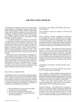
areas. Figure 3 is the photograph of a solar distillation plant,
DESALINATION 201
expensive than flat plate collectors per unit area installed and
per unit of thermal energy delivered. Solar ponds, being low-
grade heat source, can be competitive with convectional heat
sources in many applications.
Flat-plate collectors, evacuated tube collectors and focus-
sing collectors are used to produce hot water or steam as the
heat medium for the distillation units. For reverse osmosis or
electrodialysis units, photovoltaic devices are used or ther-
mal conversion systems, e.g., central receivers, to drive the
turbine generator.
A very important aspect of the solar assisted desalination
process is the cost of energy and water produced. However,
experience has shown that cost estimates are different every-
where. Labour, material cost, etc. depend on local circum-
stances, so the cost of water is not the same at all places.
Solar assisted desalination capacity is only a very
small percentage, about 0.80%, of the total world capacity
of convectional-fossil fuel fired desalination plants. A part,
0.60% is coupled to collectors or photovoltaic devices and
0.13% are wind-driven plants. The total capacity of worldwide
solar-driven desalination plants is only about 15,250 m
3
/d, and
wind driven as low as 2,530 m
3
/d.
5
irst known sketch for solar distil-
lation equipment.
18
Distillation process, operated with conventional energy
sources, i.e., low pressure steam, are applied up to very large
capacities by using various types of evaporators and are clas-
sified accordingly as follow:
Multiple-effect evaporator (ME)
Vertical tube evaporators VTE, falling or climbing
type
Horizontal tube evaporators HTE
Multi-stage-flash evaporator (MSF)
Vapor compression evaporator (VC)
Thermal vapor compression TVC
Vacuum vapor compression VVC
Mechanical vapor compression MVC
The term “evaporation” in the desalination refers espe-
cially to the vaporization of water from an aqueous saline
solution, as brackish or seawater, where the solid constitu-
ents are practically nonvolatile, in the range of working
FIGURE 3 Photograph of the Solar distillation plant in Porto Santo, Madeira, Portugal. It is the only solar plant in
operation in Europe. Has a total evaporating area of 1,200 m
2
, and consists from two different kinds of solar stills, of
the assymetrical type. The Greek design developed at the T.U. of Athens and the design developed by the university
of Berlin.
© 2006 by Taylor & Francis Group, LLC
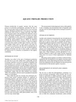
Figure 4 presents the f
202 DESALINATION
temperatures and pressures. Thus, water alone is vaporized,
which is the main product, and the dissolved solids remain
in the residual liquid, the brine.
In the chemical industry, when an evaporation process
is applied, the water vapors are usually discarded and the
emphasis is given to the recuperation of the dissolved solids.
In desalination the term “distillation” predominates over
the correct term “evaporation.” The process is performed in
evaporators, where heat is supplied to the solution, to change
phase.
The productivity is expressed either as the net evapo-
ration or “gain output ratio” (GOR), i.e., the kilos of pro-
duced distilled water per kilo of boiler steam used, (kg/kg)
or as performance ratio R. It is usually prefered, instead of
the GOR, to use the term performance ratio which defines
the mass of distillate produced per 2326 kJ (gal/1000 BTU)
of heat input to the brine heater in case of MSF distilla-
tion or to the first effect in case of multiple-effect evapo-
rators. The latter definition is thermodynamically more
accurate, as it refers to the enthalpy of the steam instead to
the mass.
Thermodynamic considerations lead to a common char-
acteristic of all distillation process, that the percentage of
evaporated water with respect to the circulating seawater is
as much larger as is the difference between the maximum
and minimum temperature of the saline solution. As the
minimum temperature is defined by the temperature of the
incoming seawater, enlarging of the temperature difference
can only be obtained by increasing the initial maximum
temperature of the salt water feed. Limitations due to the
appearance of phenomena like scale formation and corro-
sion, which are becoming more important at higher tempera-
tures, define an allowable maximum temperature for each
distillation process. An appropriate pretreatment of the salt
water is necessary to make an increase of the feed water tem-
perature possible.
The economics of the distillation process might be
affected by the following parameters:
• The chemical additives for feed water pre-
treatment
• Scale formation which decreases performance
• Increase of maintenance costs due to corrosion
Corrosion may increase fixed changes, when more
expensive materials of construction must be used.
Multiple-Effect Distillation (ME)
Theoretically, in single-effect distillation 1 kg of distillate
will be produced for every kg of steam consumed and the
gain output ratio of the plant will be 1. In fact, despite pre-
heating of the feed, a large part of the enthalpy of the vapors,
FIGURE 4 The first historically known solar distillation equipment, according to Giovanni
Batista De La Porta. The sun evaporates the water inside the glass vessels and distilled water is
collected beneath the vessels. “De distillations,” Libri IX, Rome 1608.
© 2006 by Taylor & Francis Group, LLC
DESALINATION 203
evolved in the single-effect evaporator, is lost in the con-
denser. A better heat recuperation would be obtained if the
heat, released by the condensing vapor, is not rejected in a
condenser, but is used to heat the brine of a second evapora-
tor and so on.
This leads to the concept of multiple-effect distillation,
where the vapors from one effect are used as the heat source
of the next effect, as long as the difference in temperature
between the condensing vapor and the solution is high
enough to act as the driving force in the evaporation pro-
cess, each effect being at progressively lower temperature
and pressure. Vapor condensing because of lower boiling
temperature, in each effect, produces fresh water as distil-
late, whereas the vapor from the final effect is condensed by
a circulating seawater cooling stream.
Theoretically, an additional kg of distillate would be
obtained in each consecutive effect for the same kg of
steam initially introduced into the first effect and the plant
gain output ratio would be equal to the number of effects in
operation. However, this is not true in practice. Part of the
condensation heat to be recovered is lost to the atmosphere,
in design features and in the differences of temperature used
as the plant’s driving force.
Multiple-effect distillation process uses evaporators
which are modified successors of evaporators that have been
used in sugar and other process industries for more than 100
years and have been in use for seawater distillation about
90 years. The latter were originally built for shipboard use,
the main requirements being for compactness, simplicity in
operation and reliability. In land based industrial evapora-
tor plants the requirements are mainly directed to the cost
of product water with emphasis on cheaper materials of
construction, high boiling temperatures, efficient descaling
methods and the use of the cheapest type of evaporator.
Previously multiple-effect distillation was second in
importance of the distillation process, as medium capacity
plants but day hardly is applied. Worldwide capacity of ME
plants for units producing more than 100 m
3
/d of fresh water,
is only 765,143 m
3
/day or 4.1% of total world capacity.
5
Long Tube Vertical Evaporator, LTVE Long tube evapo-
rators consist of a series of long tubes arranged vertically
inside the evaporator shell. Seawater feed may be from the
top or from the bottom, called respectively falling or rising
film LTV evaporators.
In the falling film evaporator seawater is introduced at
the top and the incoming seawater flows across an upper
tube plate and is equally distributed to the tubes, and flows
downward by gravity as a thin film. The principal advantage
of the VTE process is that high heat-transfer can be achieved,
which considerably reduces the required heat-transfer sur-
face area. This forward feed is the usual method of feeding a
multiple-effect-evaporator.
The VTE rising film is similar to falling film evaporator
except that seawater is introduced at the bottom of the first
effect, thus reducing the overall pumping requirements. Heat
transfer in the VTE evaporators is increased by using fluted
tubes, which enhance heat transfer.
Steam condenses outside the tubes, forming also a thin
film of distillate. Surface tension forces are created, which
are inversely proportional to the flute radius. This causes the
condensate film to drain from the crests to the grooves, so
that a very thin condensate layer is remaining on the crests,
which promotes heat transfer.
The flow sheet of a typical multiple-effect vertical tube
a feed heater C which uses the product vapors as heating
medium in the form of distilled water or vapor condensate.
Vapors produced in the first effect condense outside the tubes
of effect 2 and the brine is pumped from each effect to the top
of the next. The average efficiency K of each effect is usu-
ally between 0.85 and 0.95. Concerning N effects in a LTE
system, as in Figure 5, the GOR is given by the equation:
GOR ϭ K(1 Ϫ K)
N
/(1 Ϫ K) (3)
Thus when K ϭ 0.95 and the number of effects N is 15,
GOR ϭ 10 kg/kg. Doubling the effects to 30, the GOR is
only 14.9, and it will attain a maximum of 19.0 for an infi-
nite number of effects, when K ϭ 0.95.
There are some economic limitations increasing the
number of effects. The investment costs and consequently the
fixed charges are increasing almost linearly with the number
of effects. The costs of steam and water fall off rapidly at
first, but the savings diminish progressively. The total cost
of operating an evaporator leads to an optimum number of
effects, at the point where the sum of fixed costs and the cost
of utilities shows a minimum. The most probable number of
effects will be between 10 and 20.
The Multiple-Effect Horizontal-Tube Evaporator The
(MEHT) type of evaporator operates on the same principle
as the VTE evaporator, but the steam condenses on the inside
of the horizontal tubes imparting its latent heat of conden-
sation to the brine, which cascades and evaporates over the
outside of the tubes. The brine falls to the next effect by
gravity and the vapors formed in one effect are used in the
next effect. The horizontal-tube evaporator eliminates the
pumps required for each effect of the VTE brine circulation,
by an arrangement in which the effects are stacked vertically
on the top of each other. This compact arrangement of the
ME evaporators, called also multiple-effect stack (MES), is
constructed in low capacity units and though there are many
advantages, it accounts for only 1% of the world capacity.
19
Multiple-
effect-horizontal-tube evaporators are suitable to operate with
solar energy plants.
VAPOR COMPRESSION (VC)
Vapor compression (VC) distillation takes advantage of
the latent heat of the vapors produced in the process. Vapor
produced by evaporation from a salt solution is superheated
because of the boiling point elevation of the solution and
© 2006 by Taylor & Francis Group, LLC
distillation plant is shown in Figure 5. In each effect is adapted
In Figure 6 a typical HTE evaporator is presented.
204 DESALINATION
has a lower pressure than the saturation pressure of pure
water. It will, therefore, in losing the superheat, condense
at a lower temperature than the boiling point of the solu-
tion. If this vapor is compressed to a higher pressure, the
energy input results in a rise in temperature. With sufficient
rise in pressure and temperature, the recompressed vapor
might be used as a source of heat for evaporating the same
salt solution.
Heat needs to be supplied to the system only at the start-
up for elevating the temperature of the solution to the boiling
point. Once boiling has started, it is maintained by the exter-
nal supply of power and no more by the addition of heat as
the cycle is repeated.
Vapor compression distillation accounts only 3.7% of
total world wide desalination capacities and about 6.2% of
distillation processes, for units producing 100 m
3
/d or more
fresh water. Daily productivity is 686,500 m
3
/d.
5
The energy source may be mechanical or electrical
power to drive the compressors for mechanical vapor com-
pression. Thermal vapor compression, or “thermocompres-
sion,” uses high pressure steam to compress the vapors to
higher temperatures. Vacuum vapor compression uses elec-
tric or waste heat to reheat the vapors, circulating by the use
of a blower.
Mechanical Vapor Compression (MVC) The MVC process
uses compressors to reheat the vapors to higher tempera-
tures. High or low pressure compressors are used, depending
on the capacity of the system. As high capacity plants have
many stages, the necessary temperature is higher and they
are high pressure compressors. Low capacity plants use low
pressure compressors. The higher the compression pressure,
the smaller is the volume of the compressor and that of the
vapor. Due to high temperatures, high capacity MVC plants
are prone to scale formation.
cal vapor compression evaporator and the T-S diagram of the
thermodynamic operation.
20
Thermocompression Thermocompression uses high pres-
sure steam ejector to re-heat the vapors released from the
compression diagram.
Another type of thermal vapor compression operates
under vacuum inside the evaporation chamber. The low pres-
sure vapors are circulated by a vapor blower and heated by
electric heater, hot water or hot gas, according to the avail-
able heat source. A suitable adaptor for the various heat
sources is necessary.
FRESH WATER
SEAWATER FEED
BRINE BLOW-
DOWN
DECARB-
ONATOR
COOLING WATER
OUT
CONDEN-
SER
COOLING
WATER IN
VENT
BRINE
BRINE
SEAWATER
BOILER
STEAM
CONDENSATE
PREHEATED FEED
WATER
B
B
A
A
AIR
VENT
CO
2
,
D
D
D
D
C
C
CC
F
N–1 N
2
1
FIGURE 5 Flow diagram of a multiple-effect-evaporator for seawater desalination, of the falling type. Seawater is preheated in the heaters
C and pumped on the top of the first evaporator No. 1, from where falls down inside the vertically oriented tubes B. A thin film of brine is
formed inside (detail A and B). In the first effect steam from the boiler forms a thin film of condensate outside the tubes. In the following
effects the vapors of each effect condenses outside the tubes of the next effect. The rest of the space of the evaporator is then filled with
water vapors. The brine accumulates in the bottom of the evaporator from where is fed to the next effect by the pumps D. A distributor cap
is fitted on each tube to ensure even distribution of the brine. The produced fresh water is used to preheat the seawater fed in the heaters C.
Part of the seawater is acid treated and a decarbonator F, is used for the removal of air and CO
2
.
© 2006 by Taylor & Francis Group, LLC
Figure 7 presents the flow-sheet of a four-stage mechani-
last stage. Figure 8 gives a typical two stage thermal vapor
DESALINATION 205
CO
2
O
2
to ejector
Sea water
30°C Sea
40°C
Product water
Blow-down
brine
40°C
40°C
Vent
Ejector
Feed water 40°C
CO
2
O
2
Sulfuric
acid
40°C
40°C
W
E
B
O
T
F
101°C
120°C
Healing
steam
S
Capacity
selector
FIGURE 6 Flow-diagram of a multiple-effect-horizontal tube
evaporator. The effects are vertically oriented, one on top of the
other. This arrangement is compact and is called multiple-effect-
stack type (MES) distillation equipment.
19
Preheated seawater
feed is sprayed, F, onto the outer surface O of the evaporator tubes
in the first effect at the top of the column, T, where a portion of
seawater is evaporated by the heating steam S. The remaining
seawater is collected at the bottom B, of the first effect and then
sprayed onto the outer surfaces of the second effect where another
portion of seawater is evaporated, being heated by the vapor gen-
erated in the first effect. The generated vapor is delivered through
a mist eliminator section, E. The vapor itself condenses into fresh
water in the side section W. The cycle is repeated in each succes-
sive effect up to the last one. Vapors generated in the last effect is
condensed in a heat rejection condenser C.
Multi-Stage-Flash (MSF) Distillation
When saline water is heated to a temperature slightly below
its boiling point at a given pressure and then introduced into a
chamber where a sufficiently lower pressure exists, explosive
boiling will occur. Bubbles are evolving from the whole mass
of the liquid and part of the water will evaporate until equilib-
rium with its vapor at the prevailing pressure is reached.
This evaporation lowers the temperature of the remain-
ing brine. The liquid may then be passed into another cham-
ber at an even lower pressure, where it flashes again to vapor.
If a higher rate of saline water circulation is supplied, an
increased proportion of flash will occur. The increased flow
rate may be considered as a means of obtaining increased
evaporative yield in a system without increasing the evapo-
rating surface. It is, therefore, equivalent to diminishing the
evaporating surface.
Flashing of vapor requires a finite residence time of the
liquid in the evaporation chamber in order to achieve near
equilibrium conditions. For a given flow rate the residence
time is determined by the chamber length. Mass-transfer
rates in two-phase flow depend on the interfacial geometry
of the two phases and on the degree of turbulence. They
accordingly determine the residence time required and thus
the size of the flashing chamber.
On the other hand, the length of the flashing chamber
must be sufficient to achieve the required temperature rise
of the incoming seawater under the acceptable maximum
velocity inside the condensing tubes. As there are limita-
tions for both brine and feed-water flow rates, the width of
the flashing chamber becomes the important determinant for
a vacuum vapor compression unit.
MSF is the most widely applied distillation process,
especially for large units, and despite the thermodynamic
advantages of ME evaporation, all major plants installed
are of the MSF principle because of the simplicity and
reliability of the process. It accounts for 51.5% of the
world desalination capacity and 86.9% of total distillation
processes. The capacity of MSF plants capable of produc-
ing 100 m
3
/d per unit or more fresh water was, by the end
of 1993, about 9,640,000 m
3
/d, 51.5% and 8,960,000 m
3
/d,
or 71.7% of world desalination capacity for desalting plants
producing more than 4,000 m
3
/d unit fresh water.
Multi-stage-distillation process, as applied in large scale
desalting of seawater, may be considered as consisting of
three sections in handling heat: the heat input section, usu-
ally named brine heater, by condensing external steam; the
heat recovery section, in which the heat of the evaporation
is recovered in the condensers at the various stages; and the
heat rejection section, which maintains the thermodynamic
process by reducing temperature and pressure and accounts
for the last stages of the plant.
MSF distillation plants operate with recirculation part of
the brine. Recirculation can be applied so far as the concen-
tration of the scale-forming compounds does not reach, after
the evaporation, the critical point. It is a disadvantage of this
design that the brine concentration at the hottest stages of
the plant is much higher than the concentration of dissolved
solids in the seawater. The fact limits the maximum brine
temperature of the process.
Operating with this cycle arrangement, the maximum
operating temperature with acid injection is limited to 121ЊC
(250ЊF), with brine concentration 1.5 times. The number of
stages is usually limited by 2ЊC flashdown per stage, because
of the low pressure differential available at the deep vacuum
conditions prevalent in the last stages.
The total number of stages is affected by the initial
and final brine temperatures, as well as by the necessary
© 2006 by Taylor & Francis Group, LLC
increasing the plant size. Figure 9 presents a flow diagram of
206 DESALINATION
temperature gradient between stages, to maintain the ther-
modynamic cycle. However, there are practical limits in the
excessive increase of the number of stages. The additional
investment to provide further stages to the plant should be
reasonable with respect to the savings of heat obtained by the
same stages. In large multi-stage flash evaporators for desalt-
ing of seawater, the cost of the heat transfer tubes is a very
important part of the total construction cost. The tempera-
ture drop in each stage and the difference between brine-inlet
temperature at the first stage and the discharge temperature at
the last stage are the main controlling parameters of the MSF
distillation process. In a cascading flashing stream of an MSF
evaporator, the combined heat capacity of the flashing brine
and distillate streams equals that of the recirculating brine
and the temperature rise of the recirculating brine equals the
temperature drop of the flashing stream.
The number of stages in an MSF distillation plant
is related to the performance of ratio. An increase in the
number of heat-recovery stages will generally result in a
higher performance ratio for a given product-water output
and in a decrease of steam consumption at the brine heater.
The performance ratio R can be correlated to the number
of stages by the following relation:
R
no recovery stages
no reject stages
TT
TT
kg
2326 kJ
max f
oF
ϭϭ
Ϫ
Ϫ
(4)
Vapor bubbles almost explode to carry entrained brine to the
temperature losses up to 0.11ЊC (0.2ЊF) per stage. Low flash
temperatures per stage reduces flash violence and entrainment
but this increases the number of stages to 40 or more and also
increases equipment costs and inefficiency, which increase
capacity and material costs.
FIGURE 7 Flow diagram of a typical 4-stage, mechanical vapor compression plant. Incoming seawater feed is preheated in the heat-
exchanger H, by the produced freshwater and the blowdown brine. The vapors released in the first stage are flashing to the second stage and
so go on up to the 4th (or to the nth stage). The vapor from the last stage is compressed in the compressor C. Electric power is generated in
a turbine to drive the compressor C. Compressed steam is circulated through the tubes of the condenser B, where it condenses, giving the
heat to the evaporating seawater. Released vapors are used as heating medium in the second stage, etc. The condensate, i.e., the produced
freshwater, leaving the flashing chambers F is collected after further cooling in the heat-exchanger H and brine is rejected.
brine blow
down
pre-heated
distilled
water
seawater
feed
T
f
T
f
seawater
distilled water
E
E
E
B
B
D
D
D
B
B
H
C
F
F
F
F
T
e
T
e
T
d
T
d
T
k
T
k
T
max
= T
4
T
4
T
3
T
3
T
2
T
2
T
1
T
1
T
c
T
c
T
b
T
b
T
a
T
a
© 2006 by Taylor & Francis Group, LLC
product. Demisters D (Figure 5) reduce this but give additional
DESALINATION 207
Temperature differences between brine and vapor streams
leaving stages may be from 0.45 to 1.7ЊC (ϳ3/4 to 3ЊF)
besides boiling point elevation.
w diagram is given of a multi-stage-
flash evaporator and the temperature profile across the plant.
flash chambers. Configuration No. 1, with long tubes is pre-
ferred by American construction companies. The cross type
No. 2, is usually preferred by European contractors.
Combined Distillation Plants
Significant economic advantages may be expected from
combining different distillation processes, especially where
desalting plants are designed with large capacities. Studies and
design experience indicate that the combined system possesses
substantial advantages in cost compared with the unit form of
multi-stage plant of the same capacity. The savings in cost are
due primarily to lower capital investment, and lower opera-
tional and maintenance costs. A further advantage of the com-
bined plant is its high operational stability at varying loads.
Many designs have been proposed and many combi-
nations have been tried, mainly for small capacity or pilot
size plants. Commercial application used the vertical tube-
multi-stage-flash (VTE/MSF) and the vertical tube-vapor
compressor processes. Tubes with fluted surfaces are used
in the vertical tube evaporator plants to obtain enhanced
heat transfer performance. The heat recovery section of the
multi-stage-flash plant is used as feed preheater of the verti-
cal tube plant, which is the main evaporator for the distil-
late production. The combined vapor compression-vertical
tube evaporator process uses the heat recovery section of
the multi-stage-flash as preheater for the vapor compression
plant as it is more efficient than the heat-exchangers in the
single vapor compression process.
Scale Formation and Its Prevention
Formation of scale deposits on and fouling of heat transfer
surfaces is one of the most serious problems of distillation
equipment operating with sea or brackish water. As the scale
deposits lower the efficiency of heat transfer surfaces and
increase the pressure drop, pretreatment of feed water is
necessary to prevent the deposition of scale.
As the salt concentration increases during progressive
evaporation, the critical point may be reached at which the
solubility limit of scale-forming compounds contained in
the feed water, is exceeded and formation of scale occurs.
The term scale is applied particularly to describe hard,
adherent, normally crystalline deposits on the heat transfer
FEED WATER
43.5°C
43°C
2nd EFFECT
PRODUCT WATER
ANTI-SCALE
CHEMICAL
INJECTION
SEAWATER SUPPLY
VENT EJECTOR
MAIN EJECTOR
STEAM SUPPLY (32°C)
BLOW DOWN BRINE
1st EFFECT
47°C
EVAPORATING TUBE
EVAPORATING TUBE
C
T
A
C
T
FIGURE 8 A two effect reheat or thermal compression unit. The low pressure, low temperature vapors from the second effect are
sucked by the steam jet ejector A, driven by a small quantity of high pressure boiler steam, and delivers a hotter compressed mixture of
stream and vapors to the condenser tubes T of the first effect. The seawater feed is sprayed onto the outside of the horizontal condenser
tubes T. Part of the rejected brine from the last stage is used as feed to the first stage. Condensate, or product fresh water is collected in
the last stage chamber C and distributed through the pump P. (Courtesy Sasakura Engineering Co., Ltd., Japan.)
© 2006 by Taylor & Francis Group, LLC
In Figure 10 the flo
Figure 11 gives the two arrangements of the multi-stage-
208 DESALINATION
surfaces. Three simultaneous factors are required for the for-
mation of the scale:
1. Local supersaturation of the solution.
2. Nucleation, which when formed includes the rate
of further scale deposition.
3. Sufficient contact time of the solution and the
nucleus.
Under certain conditions a soft, amorphous material,
called sludge, may be deposited or remain suspended in the
brine and is generally more easily removed than hard scale.
If the ions contained in seawater are combined in the
form in which they usually deposit, the resulting compounds
will be approximately:
CaCO
3
109 mg/L
CaSO
4
· 2H
2
O 1,548 mg/L
MgCl
2
3,214 mg/L
MgSO
4
2,233 mg/L
NaCl 26,780 mg/L
assuming that hydrogen carbonate decomposes to carbon-
ate before precipitation occurs. Alkaline scale, CaCO
3
and
Mg(OH)
2
, results from the decomposition of the hydrogen
carbonate ion. On heating seawater up to 82ЊC (180ЊF), the
hydrogen carbonate ion decomposes and calcium carbonate
is formed.
A second type of scale, called acid scale, is due to three
forms of calcium sulfate: the anhydrite CaSO
4
, the hemihy-
drate and the dihydrate CaSO
4
· 2H
2
O, or gypsum. While the
precipitation of CaCO
3
and Mg(OH)
2
is mainly affected by
CO
3
2–
concentration, pH and temperature affect the solubility of
calcium sulfates in addition to the concentrations of other ions
present. CaSO
4
has as well decreasing solubility in the tem-
perature ranges of interest. The solubility increases in chloride
solutions, as the concentration approaches 4 to 5% chloride and
then decreases to values comparable to those in chloride free
water as the chloride concentration becomes 10 to 15%.
Maximum brine temperature provided in the design, maxi-
mum allowable brine concentration and brine recirculation rate
are also affected by the formation of scale. These operating
variables and the plant availability are closely tied to the eco-
nomics of the process as the production rate is generally low-
ered. Periodic plant shutdowns for descaling would be required
either by an acid clean or, in extreme cases, by mechanical
cleaning of the tubes. Incrustation allowances to reduce the
frequency of shut-downs are made in designing evaporators,
which are provided with a sufficient larger heat-exchange sur-
face in order to maintain the design capacity. The term fouling
is often extended to this type of admissible scaling.
VVC DISTILLER
ALTERNATIVE BACK-UP HEAT SOURCES
ELECTRIC HEATER
WASTE HEAT
CONDENSER
SCALE
INHIBITOR
FEEDWATER
FEED
PREHEATER
BRINE
PRODUCT
WATER
EVAPORATION
VACUUM PUMP
VENT
VAPOUR BLOWER
BRINE
ELECTRIC HEATER
WASTE HEAT
EXCHANGER
EXTERNAL HEAT SOURCE
CONDENSATE
STEAM
BRINE
FIGURE 9 Flow diagram of a vacuum vapor compression (VVC) unit. The vacuum vapor compression distillers are small capacity units,
and can produce fresh water from any kind of water, as dirty waters, with low energy consumption. It operates without acid treatment at
70ЊC (158ЊF) and uses, as heat source, electricity or can be combined with hot gas or hot water 80ЊC. The salt water feed is preheated and
sprayed to the top of the evaporator A, where it is distributed as a thin film over the outside of the tubes T. The thin film boils at the tube
surface due to condensation of the hotter vapor inside the tubes. The vapor thus created is compressed in the blower B and its temperature
is raised, before it passes to the inside of the tubes T, where it condenses to form fresh water. Most of the heat is thus effectively recycled.
C, D, E, represent the auxilliary parts of heating which can be adapted to the main distillation unit U, according to their availability.
(Courtesy Sasakura Engineering Co., Ltd., Japan.)
© 2006 by Taylor & Francis Group, LLC
DESALINATION 209
heat recovery stages
heat rejection stages
cooling water
cooling water
chemicalsvent
brine
blowdown
seawater
feed
seawater
feed
fresh water
fresh
water
brine
blow down
condensate
boiler
steam S
brine heating
temperature
T
f
T
f
T
F
T
B
T
O
T
C
T
C
T
max
T
max
T
max
– T
C
FIGURE 10 Flow diagram of a multi-stage-flash evaporator with brine recirculation, and temperature profile across the plant. Cold
water feed is pre-heated inside the condenser tubes of the heat rejection stage A, then circulating through the condensers of the recovery
stages, is heated to temperature T
c
. Finally is heated by steam and reaches the highest temperature in the process T
max
. By this temperature
is fed to the 1st stage of the recovery section. The recovery and the rejection sections are enclosed in a single long vessel. The rejection
stage removes excess heat from the flashing brine. Each stage is operating at a lower pressure than the preceding stage, with temperature
fall from stage to stage. The vapor generated in the flash chambers condenses on the tubes of the condenser giving its latent heat of con-
densation to the heated seawater into the tubes. Leaving the heat rejection stage, brine is blow-down. Usually 50% to 75% of the brine
recirculates after mixing with cold seawater. In the temperature profile, the stepped line shows the temperature fall at each stage of the heat
recovery and heat rejection sections. T
max
is the maximum temperature to which the seawater feed is heated. T
f
is the discharge temperature
of the brine in the last stage and T
o
is the outlet temperature from the recovery stage to the rejection stage. T
F
is the temperature of cold
seawater feed. These temperatures are correlated to the performance ratio R.
There are several techniques used to avoid deposition of
scale. Calcium carbonate and magnesium hydroxide forma-
tion can be controlled by acid injection and pH adjustment
or by the addition of polyphosphates. Sulphuric acid trans-
forms the carbonates to sulphates so that only one type of
scale-forming salt remains present. Phosphates precipitate
calcium and magnesium as sludge, minimizing the effects
on the heat transfer surfaces. Either of the chemicals is intro-
duced into seawater before its entry into the deaerator. In the
deaerator the dissolved gases, together with carbon dioxide
evolved during acidification, are eliminated. The pH of the
treated seawater is controlled by the addition of dilute caus-
tic soda, which binds the remaining carbon dioxide.
Calcium sulphate scale is more difficult to control.
When formed on heat transfer surfaces, removal is difficult,
if not impossible. To prevent deposits two methods may be
applied. Seed crystals are injected into the hot seawater to
promote precipitation of scale-forming compounds on these
seeds, which then form a sludge rather than a deposit on the
heat transfer surfaces. Ion exchange treatment is applied
to eliminate completely both calcium and magnesium ions
from the solution.
A technique of seawater pretreatment is the LMC or
lime-magnesium carbonate process. 70 to 80% of the cal-
cium originally present in seawater is removed and this
permits operation at higher temperatures and concentration
© 2006 by Taylor & Francis Group, LLC
210 DESALINATION
factors, thereby increasing the water recovery ratio for
saline solutions and favourably affecting the economics
of the desalting process. Treatment of the seawater with
H
2
SO
4
, on the other hand, reduces the corrosiveness of the
water by eliminating dissolved oxygen and carbon dioxide
in the deaerator.
Acid treatment converts bicarbonate to carbon dioxide
gas, whereas caustic treatment yields the carbonate ion,
which combines with the calcium ion present in seawater
to precipitate calcium carbonate. Nucleation of scale on the
heat transfer surfaces is inhibited and precipitation of solids
is dispersed in suspension by the addition of small amounts
of certain commercial preparations. The sludge formed is
then removed in the blowdown.
The first commercially available scale control compound
was Hagevap, a mixture of sodium tripolyphosphate lignin
Condenser Tube
Condenser Tube
Mist Separator
Mist Separator
Fresh Water Produced
Partition Plate
Partition Plat
e
Brine
Tube Plate
Water Chamber
2
1
Brine
FIGURE 11 Drawing of a long tube multi-stage-flash (No. 1) and a cross tube multi-stage-flash chamber. The long tube configuration has
a condenser running through each stage and the tubes are parallel to the flow direction of the flashing brine. High technical skill is necessary
to seal the partition plates where the condenser runs through the partition plate. Long tube MSF plants are adopted for larger desalination
plants. The cross tube type desalination units have the tubes across the top of the flash chamber and at right angles to the flow direction of
the flashing brine. The cross tube configuration has condensers independent of each other and is mainly used for smaller desalination plants.
(Courtesy of Sasakura Engineering Co., Ltd., Japan).
© 2006 by Taylor & Francis Group, LLC
DESALINATION 211
sulfonic acid derivatives and various esters of polyalkylene
glycols. Polyphosphates act as sequestrants for calcium and
magnesium ions. Lignin sulfonic acid, starch, tannin, etc. act
as dispersants in coating surfaces such that scale adherence
and crystal growth are inhibited. Polyalkylene-glycols are
surface active agents which tend to retard foaming of the
seawater.
The use of polyphosphate based additives is limited to
temperatures below 90ЊC (190ЊF). Above this temperature,
polyphosphates undergo chemical changes which restrict
their effectiveness as antiscaling agents. Other additives are
low molecular weight polyacrylic acid or 10% ethyl acrylate-
acrylic acid copolymer. An optimum polymer concentration
of about 2 mg/L was observed to be most effective.
Materials of Construction: Corrosion
The selection of suitable metals to construct desalination
plants is of prime importance as the use of inadequate mate-
rials may lead to shutdowns, increased replacement and
maintenance costs and affect the overall economics of the
plant.
The optimization of a distillation process has as a first
object the minimization of the amounts of thermal or mechan-
ical energy and of the amount of equipment and, hence, the
amounts of materials used. Quite often, in such optimization
studies, as energy goes down equipment goes up, and vice
versa. Thus the most economical balance must be struck.
Often this is at a point where the energy cost and the capital
cost of the equipment are about equal.
Of the billion dollars per year to be spent for plants,
materials for the equipment might be regarded as at least
50%, with costs of engineering, fabrication, transportation,
installation, etc. accounting for the rest. Of materials used
in equipment by far the largest amount will be for metals,
particularly those metals which are least corroded by sea-
water. These are not the most abundant or least expensive.
The specification of these metals for equipment—those
which are suitable for withstanding the corrosion and other
deleterious effects of this service—are of greatest impor-
tance. Their fabrication into sheets, tubes, shapes, and then
finished vessels and parts and accessories will be a great test
of the skill of the metallurgist, the chemical engineer, and the
mechanical engineer.
Membrane Processes
Membrane processes are classified in two main categories:
• Methods which separate salts from the water, in their
ionic form, called ionic processes. Electrodialysis
and ion-exchange are the separation processes for
desalination.
• Methods which separate water from a salt solution.
Reverse osmosis, nanofiltration, ultrafiltration and
microfiltration are the main processes of this type
of separation which are applied to desalination or
to water purification.
Ionic Processes Common salt, and other salts as well as
acids and bases, are ionized in solution into the positive
(for example, sodium ions) and the negative (for example,
chlorine ions). Whereas in distillation processes the amount
and kind of salts dissolved in the raw feed water are of no
importance to the process and do not affect the economics,
in all ionic processes the amount of dissolved salts is of pri-
mary importance. In electrodialysis, the amount of salts to
be removed affects the consumption of electrical energy and
in ion-exchange affect the amount and the cost of regenerant.
Thus, ionic processes are much too expensive to use with
the higher salt concentration of seawater, as compared with
brackish, river or estuary water. In general ionic processes
depend on specially developed polymeric resins in the form
of membrane in the case of electrodialysis and as granules
for ion exchange.
Ion Exchange The chemical system for removal of the ions
of salt is called ion exchange and has long been used in the
reverse process in which, for example, the sodium ion of salt
is used to replace calcium ions to “soften” hard water. In
this case the “bed,” of ion-exchanging material consists of
granules of resin which have the property of removing posi-
tive or metal ions from a circulating aqueous solution by dis-
placing them by a chemical bond with the resin of the bed.
This replaces them with ions which are loosely bound in
the molecular structure of the resin. When the positive ions
of the resin are completely replaced, an aqueous solution,
relatively concentrated in the other positive ion, is cycled,
and the process is reversed. Other beds of resin have the
properties of exchanging negative ions.
Similarly the sodium ion of a salt solution such as sea-
water passing through a suitable first bed may be interchanged
with a hydrogen ion from the resin to leave the sodium ion
in a loose combination with the resin and a resulting hydro-
chloric acid in the effluent solution. This solution is then
passed through a second resin bed, in which a hydroxyl ion
interchanges with the chlorine ion to give a resin chloride
combination and an equivalent amount of chemically formed
water which is added to the aqueous stream.
When the two resin beds have interchanged all of their
respective hydrogen and hydroxyl ions, their activity ceases
and they must be generated. This is done by stopping the
flow and adjusting valves to take the beds off-stream and to
pass through the first bed a dilute solution of sulfuric acid
and then to pass through the second bed a dilute solution
of caustic soda. The hydrogen ions of the sulphuric acid
displace the sodium ions on the resin of the first bed to give
sodium sulphate in its effluent which is run to waste and
the hydroxyl ions of the caustic soda displace the chlorine
ions on the second resin to give sodium chloride (salt) in the
effluent of the second bed, which also runs to waste. Again,
the ions on the beds are completely interchanged, the beds
are thus generated and the controlling valves are adjusted,
with those allowing the sequential flow of the original sea-
water being opened to allow the process to be repeated.
This process thus required both sulphuric acid and caus-
tic soda in amounts which are chemically equivalent to the
© 2006 by Taylor & Francis Group, LLC
212 DESALINATION
amount of salt present. Usually, at least 50 to 100% excess of
each is used. This will represent a very high and impossible
cost for large-scale desalination of seawater.
In special cases, particularly for desalinating brackish
water, ion-exchange beds have been used, since only a
relatively smaller amount of chemicals is required to inter-
change ionically with the salt in the feed solution. Thus
water containing 1750 ppm of salt would be regarded as
non-potable, but it would require only about 5% of the
chemicals that seawater would require. On the other hand,
the energy cost for its desalination by evaporation or
RO would not be so greatly different from that required for
seawater because in these processes it is the water which is
being separated.
For emergency kits, packages of ion-exchange resins
have been made to have only a single use, e.g. by avia-
tors downed at sea. Seawater is passed through these small
“beds” to make a small amount of drinking water. Provision
for regeneration of the resins would be complicated and the
resins are discarded when charged with sodium and chlorine,
respectively.
The simplicity of ion exchange has attracted much effort
to finding less expensive methods of generation of the ion-
exchange resins. Carbon dioxide is a weak but cheap acid,
as lime is a cheap alkali, and special resins and processes
have been developed to use them and also to use the major
differences of ion exchange equilibria at 80ЊC as compared
to those at room temperature.
Ion exchange processes depend upon good resins.
Excellent resins are available and they are not the limiting
factor. The major cost is that of the chemicals required for
the much less than stoichiometric replacement of salt by two
chemicals. In desalination the ion-exchange process is used
mainly for pre-treatment of brackish water for electrodialy-
sis or reverse osmosis.
Electrodialysis, ED
Electrodialysis is the transport of ions through ion-selective
membranes as a result of an electrical driving force. The
process takes advantage of the ability of these membranes
to discriminate between differently charged ions, allowing
for free passage to either cations or anions and being imper-
meable to ions of the opposite charge. Electrodialysis is a
desalination process of brackish water and, under certain
circumstances for seawater as well.
The electrical mechanism of ion removal is much more
complicated, and much cheaper, than ion exchange since it
uses electrical energy rather than chemical equivalence to
replace the two ionic changes of a molecule salt, since an
electric current assists greatly the dialysis or movement of
the ions through membranes permeable to the positive ions
and to the negative ions, respectively. A membrane which
is permeable to sodium ions forms the wall on the side of
a channel of flowing saline water and a membrane perme-
able to chlorine ions forms the wall on the other side. The
deionized water flows between the two membranes, and the
electric current may be regarded as flowing at right angles.
The other aqueous streams on the other side of the respec-
tive membranes may flow out counter-currently in the other
direction (Figure 12).
The electrodialysis process is performed in cells consist-
ing of many compartments formed alternatively by an anion
and a cation exchange membrane placed between an anode
and a cathode (Figure 12). Multicompartment electrodialy-
sis cells are usually termed as electrodialysis stacks. A mem-
brane pair is called a “cell pair” and consists of a:
• Cation transfer membrane
• Anion transfer membrane
• Demineralized water flow spacer
• Concentrate water flow spacer
A typical membrane stack contains 300 to 500 cell pairs,
depending on feed salinity. If the feed water has a low salin-
ity, it is possible to obtain an acceptable potable water in
Na
+
O
2
Cl
2
H
2
H
+
Na
+
Na
+
Na
+
Na
+
Na
+
Cl
–
Cl
–
Cl
–
Cl
–
Cl
–
Cl
–
OH
–
feed water
–+
brine
brine
brine
current
desalinated water
feed
water
electric DC
A
C
A
CA
C
SSSSS
7654321
FIGURE 12 Flow diagram of a multicomponent electrodialysis
cell, with 7 compartments showing the principle of the process
operation. The saline water feed is pumped through the compart-
ments, s, of the membrane stack and, when a direct current poten-
tial is applied, cations pass easily through the cation- permeable
membrane and are stopped when they reach an anion-permeable
membrane. Similarly anions have free passage through the anion-
permeable membrane and are stopped at the cation-permeable
membrane. The ion concentration increases in the alternate compart-
ments.
3,5
Simultaneously the compartments between them become
depleted of ions.
2,4
Hence two streams of water are extracted from the
electrodialysis stack: one stream with low ion concentration, which
is the product water, and one stream with high salt concentration,
which is the reject brine. Separate feed and brine blowdown is pro-
vided for the first and last compartments containing the anode and
cathode respectively, since corrosive oxygen, chloride and hydrogen
gases are released.
© 2006 by Taylor & Francis Group, LLC
DESALINATION 213
a single pass through the electrodialysis stack. If the feed
water is high in salinity this is not normally practical. Feed
velocities have to be maintained above a certain minimum
value and this requirement is handicapped by the necessity
to provide also for a minimum residence time of the fluid
in the compartment. An increase of the current density may
lead to concentration polarization, a phenomenon that can
stop process operation.
Figure 13 is a view of an electrodialysis stack before
assembly, that shows the main components. Typically the
design is based on the configuration used in the plate and
frame filter press. The end frames have provisions for hold-
ing the anode or cathode and are usually made relatively
thick and rigid that pressure can be applied to hold the stack
components together. The inside surfaces of the end frames
are recessed to form an electrode-rinse compartment and pro-
visions are made for introducing and withdrawing the solu-
tions. Spacer frames with gaskets at the edges and ends are
placed between membranes to form the solution compart-
ments when ion exchange membranes and spacer frames are
clamped together.
These are various electrodialysis systems:
• The conventional batch-type which was the first
commercially developed system.
• The continuous-type unidirectional electrodialysis
system.
Both types of the electrodialysis systems have some
operation disadvantages and limitations. Ionic movement is
unidirectional. In such systems cations are moving toward a
fixed cathode and anion toward a fixed anode. Sealing form-
ing salts, colloidal particles or slimes, slightly electronega-
tive are accumulated on the surface of the anion-exchange
membrane causing membrane fouling.
• Electrodialysis reversal (EDR) is a system designed
for continuous operation. The polarity of the elec-
trodes is reversed 3 to 4 times per hour.
This operation system reverses the direction of ion movement
within the membrane stack, controlling thus scale formation
and fouling.
To day almost all electrodialysis cells are constructed
to operate with the reversal arrangement. Figure 14, gives a
flow diagram of a reversal electrodialysis system, in a vertical
arrangement.
The electrodialysis process is related to Faraday’s law
which states that the passage of 96,500 Ampere-s transfers
theoritically one gram-equivalent of salt. The needed current
for transferring a specific quantity of salt is given by the
equation:
I
Fm c
eN
d
ϭ
⌬
.
(5)
If current efficiency e is 100%, 96,500 A-s will transfer one
gram-equivalent of sodium ions, or 23 g Na
ϩ
, to the cathode
and one gram-equivalent of chloride ions, or 35.5 g Cl
Ϫ
to
the anode.
Electrodialysis is applied usually to brackish water
desalination up to 7 g/kg salinity. Sea water can be used also
to produce water around 0.50 g/kg or less but energy con-
sumption is very high. In reversal electrodialysis scaling is
very low, almost zero, but in conventional ED pretreatment
of feed water is necessary.
Energy input for electrodialysis depends on feed water
salinity and varies from 19 to 20 kWh/m
3
(72 to 76 kWh
per 1000 gallons) for seawater feed. For brackish waters the
required energy is 2.4 kWh/m
3
(9 kWh per 1000 gallons) for
Spacer
frames
Anode feed
solution
Electrode
rinse solu-
tion
Concentrating
Solution
Product water
Feed solu-
tion
Spacer
frames
Cation exchange
membrane
More membranea, spacer
frames, and cathode
Anion exchange
membrane
A
N
O
D
E
FIGURE 13 View of part of an electrodialysis stack before assembly.
Component 1 is the one end frame, each of which holds an electrode
and has opening for feeding and withdrawal of the depleting, the con-
centrating and the electrode rinse solutions. Compartments 3 and 5
are spacer frames which have gaskets at the edges and ends and form
solution compartments with the membranes when they are clamped
together. Many membranes and spacers clamped together form an
electrodialysis unit.
raw water
feed
raw water
feed
–
–
+
+
raw water
feed
raw water
feed
desalinated
water
desalinated
water
brine
brine
Na
+
A
A
A
A
A
A
C
C
C
C
C
C
C
C
Na
+
Na
+
Na
+
Na
+
Na
+
Na
+
Na
+
Na
+
Na
+
Na
+
Na
+
Cl
–
Cl
–
Cl
–
Cl
–
Cl
–
Cl
–
Cl
–
Cl
–
Cl
–
Cl
–
Cl
–
Cl
–
FIGURE 14 Flow diagram of an electrodialysis reversal cell.
B represents the one-way operation and D the operation after
the reversing of the polarity. Cathode or anode are reversing and
become anode and cathode respectively. Ion movement reverses as
well and concentration compartment acts as dilution compartment.
Blowdown brine circulates in fresh water tubes and vice-versa.
© 2006 by Taylor & Francis Group, LLC
214 DESALINATION
feed water having 2,500 ppm and about 3.9 kWh/m
3
(14.8
kWh per 1000 gallons) for feed water containing 4,500 ppm
total dissolved solids. The pumps operate at low pressure of
350 to 700 kPa (51 to 101 psi).
Electrodialysis has a variety of applications, in addition
to that of fresh-water production, i.e., for the treatment of
wastes, for the recovering of trace elements from effluents and
for concentration of various solutions, such as fruit juices.
To the end of 1993 world capacity of electrodialysis
plants producing more than 100 m
3
/d/unit was 1,070,005 m
3
/d
covering only 5.7% of the total desalination capacity, and
14.8% of the membrane processes.
Ion Exchange Membranes The ion-exchange membranes
are membranes selective either to cations or to the anions.
When a cation-selective membrane is immersed in an elec-
trolyte solution the cations in solution will enter in the resin
matrix and replace the cations present. The anions are pre-
vented from entering the matrix by the repulsion of the
anions affixed to the resin. The opposite phenomenon takes
place when an anion-selective membrane is immersed in an
electrolyte solution. Ion exchange membranes are essentially
ion-exchange resins cast in sheet form.
Membranes of synthetic resins have been developed
which are highly selective to the passage of positive ions,
and others have been developed which are highly selective
to the passage of negative ions. Hundreds of membranes
form passages in parallel between somewhat like a plate and
frame filter press., which is the electrodialysis stack. A stack
is presented in Figure 15.
Counter-ions within an ion exchange resin or membrane
are ions with a charge opposite to the charges affixed to the
membrane matrix. Co-ions are ions with the same charge as
the fixed charge of the matrix. Hence, ion selective mem-
branes are selectively permeable to counter-ions and selec-
tively impermeable to co-ions. The selectivity, which might be
expressed in terms of the transference number of counter-ions
in the membranes, is not generally restricted to all ions of the
charge. Membranes may well be more selective to some ionic
species than to others. There are commercially available mem-
branes that will selectively transport univalent ions in electro-
dialysis. With these membranes not only the concentrations
but also the composition of electrolyte solutions can be altered.
A membrane possessing specific selectivity between divalent
and univalent ions would be useful for removing sulfate from
a solution of chloride and sulfate, or to fractionate a mixture
of the ions into two solutions, each one containing only one
of the ions.
Transport numbers of ions in the ion exchange mem-
brane are different from those in the solutions on both sides
of the membrane. Because of the lower transport number of
ions in the solution, the number of ions transported to the
membrane surface by the electrical current is in deficiency to
the ions removed from that surface and transferred through
the membrane. The opposite phenomenon occurs on the
other side of the membrane. A greater number of ions are
transferred from the entering to the outgoing membrane sur-
face than can be carried away by the electrical current. Two
boundary layers with the opposite concentration gradients
are formed at both sides of the membrane. This tendency
for concentration and depletion is opposed by diffusion and
physical mixing. Hence, the thickness of the boundary layers
depend on hydrodynamic conditions and on the degree of
turbulence. However, there remain layers adjacent to the
membrane in which the solutions are completely static.
Increasing the current density has the effect of increas-
ing the concentration gradients at both surfaces of the
membrane and the point may be reached at which the con-
centration of ions at the entering side of the membrane
approaches zero. This is the limiting current density. When
the limiting current density is exceeded, hydrogen and
hydroxyl ions are transported through the solution and the
membrane causing changes of pH inside the membrane
and at the boundary layers of the solutions, as well as an
increase in the overall electrical resistance. The desired
ions participate with only a small amount in the transport.
The phenomenon is termed concentration polarization and
is the major limitation of the production rates achievable
by electrodialysis.
The increase in the pH of the solution associated with
polarization promotes the formation of alkaline precipitates
such as calcium carbonate and magnesium hydroxide on
the membrane surface. Membrane scaling causes additional
electrical and flow resistance, a decrease in electrodialysis
FIGURE 15 Photograph of an electrodialysis reversal stack
with 500 cell pairs in vertical arrangement. (Courtesy Ionics Inc.,
Watertown, Mass. USA.)
© 2006 by Taylor & Francis Group, LLC
DESALINATION 215
FIGURE 16 A cell pair spacers and anion and cation membranes
with the corresponding manifolds. Water is circulating through the
paths of the spacer. (Courtesy Ionics Inc., Watertown, Mass, USA).
efficiency and an increase in pumping power requirement
and mechanical damages in some occasions.
Ion exchange membranes are very thin, about 0.5 mm
(0.020 inches), and they are supported by spacers as shown
low density polyethylene having manifold cutouts which
match the membrane cuts as it is shown in Figure 16.
Membrane life is short, from 3 to 6 years, depending
on scale formation, fouling and the poisoning of the mem-
branes. Poisoning of the membranes occurs from chemical
agents such as chemicals for pre-treatment. The membranes
lose their characteristic properties, their volume is increased,
their water content decreased and they deteriorate easily.
Scaling, fouling and poisoning of the membranes have
influence not only on membrane life but also on membrane
efficiency, which drops considerably after long period use.
Reverse Osmosis, RO Reverse osmosis separates pure
water molecules from a salt containing solution through a
semipermeable membrane having extreme fine pores.
Osmotic flow, direct or reversed, depends on the selective
properties of some membranes to allow certain components
of a solution, usually the solvent, to pass through the mem-
brane. This intrinsic property of the membrane is termed as
semipermeability. If two solutions of different concentration,
or a pure solvent and a solution, are separated by a semiper-
meable membrane, the solvent will flow under normal con-
ditions from the less concentrated department through the
membrane into the concentrated solution, with the tendency
that both solutions reach the same concentration. This flow
is known as osmosis. Osmotic flow through the membrane
will stop when the concentrated solution reaches a suffi-
ciently higher pressure than prevailing in the less concen-
trated solution or the solvent compartment. The equilibrium
pressure difference between solvent and solution, or the two
solutions, known as osmotic pressure, is a property of the
solution. Equilibrium can also be reached by applying an
external pressure to the concentrated salt solution equal to
the osmotic pressure. Further increase of the pressure on the
concentrated solution, beyond the osmotic pressure, causes
reversal of the osmotic flow. Pure solvent passes from the
solution through the membrane into the solvent compart-
ment. By applying a pressure higher than the osmotic the
phenomenon is reversed and water flows from the con-
centrated solution to the dilute. This is the basis of reverse
osmosis, the major attractions of which, from an economic
point of view are its simplicity and the relatively low energy
consumption.
Reverse osmosis has some analogies with filtration
in that both remove substances from a liquid. As matter,
removed by reverse osmosis is in solution, the process pre-
viously was termed “hyperfiltration,” when the membranes
used were highly semipermeable with respect to low molec-
ular weight solutes. On the contrary, when the membranes
used have little or no selectivity for such solutes but they
may be applied for the separation of colloids or macromol-
ecules from low molecules solutes, the method is called
“ultrafiltration.” In fact ultra, a Latin word, is identical to
the Greek word hyper. Today high pressure, low molecular
matter separation is called “reverse osmosis” and lower pres-
sure low molecular separation is called “nanofiltration.” By
chemical engineering point of view reverse osmosis, nano-,
ultra- and micro-filtration can replace, in some extent other
unit-operation separation methods as these are shown in
fication of water of solutions related or not to desalination
methods and reverse osmosis and nanofiltration for desali-
nation of seawater brackish or natural waters, as well.
Applied pressures are higher for the reverse osmosis
method and low for microfiltration and, on the other hand,
porosity of membranes is decreasing from micro-filtration to
reverse osmosis as follow:
Applied pressure, bars Porosity
Reverse Osmosis, RO 30 to 70 5 to 20 Å
Nanofiltration, NF 20 to 40 10 to 20 Å
Ultrafiltration, UF 5 to 15 20 Å to 0.1 mm
Microfiltration, MF 1 to 4 0.1 to 2 mm
Reverse osmosis, for desalination of sea or brackish
water, by the end of 1993 had a world capacity of 6,109,250
m
3
/d per unit or 32.7% of total world capacity. This capacity
gives RO second place in fresh water production worldwide.
The vapor gap osmotic distillation process is a fore-
runner of the reverse osmosis process. It is based upon the
difference between the water vapor pressures over a saline
solution and that over pure water.
Reverse osmosis as a process was developed first with the
plate and frame concept, using the filter-press principle. This
© 2006 by Taylor & Francis Group, LLC
in Figure 13. Spacers are made usually from two layers of
Figure 17. These four methods can be applied for the puri-
216 DESALINATION
configuration is now coming back, having many improve-
ments and makes use of a rigid plate with the membranes
mounted on opposite sides and sealed to the plate. Salt water
under pressure is following on the outer side of the mem-
brane and the product water is forced through the membranes
into the interior of the porous plate, which serves as mem-
brane support.
Two other configurations, are in use: The tubular and the
spiral wound. Both, as the plate and frame concept, use flat
sheet membranes, and another concept uses membranes in
the form of hollow fibers.
All membranes are assembled in units called modules.
Each module is self-contained and can be used as an indepen-
dent reverse osmosis unit. Most often, many modules con-
nected in series are used to increase capacity. Semipermeable
membranes are very thin, as are ion-exchange membranes
and fragile, and they need special support to withstand the
pressure applied for the separation. Assembling the vari-
ous types of modules special care must be taken to support
the membranes properly. The fact that water flow through
a membrane is proportional to the membrane area and
inversely proportional to its thickness renders a module a
device requiring the maximum possible area per unit volume
of water passing through the membrane. The membranes
are vulnerable to mechanical damage, fouling and scaling as
well as to concentration polarization phenomenon. A perfect
module has the following advantages.
• Minimizes the effects of concentration polarization.
• Has high resistance in seawater corrosion and in
the cleaning chemicals.
• Continuous operation at high pressure.
• Almost constant quality of freshwater produced.
Reverse osmosis is a method used not only for desalina-
tion of sea or brackish water, but also for the purification of
a large variety of various solutions in the chemical industry
by using suitable semipermeable membranes.
EVAPORATION
DISTILLATION
ADSORPTION/REGENERATION
ADSORPTION/REGENERATION
ION-EXCHANGE
CENTRIFUGATION
FLOCCULATION/PRECIPITATION
CONVENTIONAL FILTRATION
DECANTING
35
30–60 Bar
100
1000 100,000
1.0
10
20–40 Bar
5–10 Bar
1–4 Bar
Pressure
Particle size
Porosity
Separation Process
46 4610
2
10
3
10
4
46 10
5
46 2410
6
A
µm µm
MF
UF
RO
NF
°
A
°
FIGURE 17 Particle size separation by various membrane and the range where they can replace the conventional
chemical engineering separation methods. The particle size range for each membrane separation method depends on
the porosity of the membrane, increasing with the particle size, and on the pressure which is decreasing proportionally
with porosity increase.
© 2006 by Taylor & Francis Group, LLC
DESALINATION 217
Ultrafiltration and microfiltration do not desalinate waters
directly but are used for pretreatment of various kinds of solu-
tion and water, depending on the molecular weight of the
dissolved or suspended matter previous to reverse osmosis
treatment.
Reverse Osmosis Membranes The reverse osmosis mem-
branes are the main and more delicate component of the
method. They are usually permeable to some species, as water
and impermeable to other, as salts. They are characterized by
two important parameters: The water flux, or water perme-
ability and the salt rejection. Concentration polarization plays
a significant role and influences both the above parameters.
The water flux at a given temperature is determined by
the membrane properties and is defined by the equation:
J
v
ϭ L
p
( ⌬ P Ϫ s ⌬ ⌸) m
3
/m
2
s. (6)
Salt rejection is the ability of the membrane to reject the
solution salts and leave only the solute, i.e., the water to pass
the membrane mass. A perfect membrane would reject all
salts contained in the feedwater and be highly permeable to
the flux of water, or solute. Commercial membranes are not
ideal and have certain amount of salts to move through the
membrane. The salt rejection is defined as:
% Salt rejection
product concentration
feedwater concentration
ϭϫϫ100. (7)
A module characteristic is the recovery or yield which
defines the fresh water product, m
3
/d, to the feed water flow,
m
3
/d as well.
R ϭ m
d
/m
s
(8)
R is influenced by the required salinity in the product, fresh
water.
The required mechanical energy to drive the RO pumps
is determined by the required separation pressure, which
in turn is proportional to the salt content of the feedwaters.
It ranges between 8.0 to 12.0 kWh per m
3
freshwater pro-
duced, from seawater feed and 2 to 3.5 kWh/m
3
of brackish
water feed. The corresponding pressure is 56 to 70 bars for
seawater (812 to 1015 psi) and 20 to 28 bars (246 to 406 psi)
for brackish water.
There is a large variety of membranes prepared from
organic materials. For commercial use up to now the types
of these composite membranes in general use are the ultra-
thin composite-spiral-wound membranes and the hollow
fine fiber membranes. The best developed composite mem-
branes are: Cellulose triacetate films deposited on a cellu-
lose diacetate-cellulose nitrate support, furfuryl alcohol film
on a polysulfone support and polyamide film on a polysul-
fone support. The polyamide-film membranes provide the
best desalination performance. This development in mem-
brane preparation brought the reverse-osmosis process next
in importance to distillation during the last years so that dis-
tillation and reverse osmosis are today leading processes in
seawater desalination.
The way by which the membranes are supported and
the properties of the membranes define the reverse osmosis
system.
A way to assemble membranes is the spiral wound module
(SWM). Spiral membranes are cellulose acetate polymers or
can be made of the thin film composite type. Spiral mem-
branes have a diameter of 5.1 to 30 cm (2.0 to 11.8 inch) and
a packing density of about 600 m
2
/m
3
.
Another module system is the tubular (TM) where the
membrane surface is packed in a shell and tube arrangement.
The membranes, usually cellulose acetate, are mounted
inside the tubes made of metal or plastic. The active layer,
i.e., the permeable layer, may be either on the inside or the
outside of the tubes.
The hollow fine fiber module (FHFM) are very thin fibers,
similar to human hair thickness. Their advantage is their
high surface area. Inside the modules they pre sent a packing
area exceeding 30,000 m
2
/m
3
of water produced. Millions of
fibers are assembled inside a cylindrical bundle embedded
reverse osmosis modules commercially available.
Freezing Processes
All variants of the freezing processes are based on the
well-known phenomenon that, when a saline solution is
cooled to its freezing temperature, ice crystals of pure water
will form and the brine will be enclosed in the slurry.
The temperature of freezing is fixed by the concentra-
tion of the brine, while evaporation can operate over a wide
temperature range. Freezing has basic advantages:
1. much lower latent heat of phase transition in the
solid state than for evaporation (0.33 ϫ 10
3
J/kg
against 2.49 ϫ 10
3
J/kg or 143.2 BTU/lb against
968 BTU/lb).
2. less heat losses (gains) because of working at
temperature closer to the ambient;
3. no scale-formation from the usual impurities;
4. less corrosion of steel at the freezing point than at
the boiling point of water; and
5. cheaper materials of construction may be used.
Against these there are basic disadvantages:
1. the time required for phase transition from liquid
to solid is very much greater than that required
from liquid to vapor;
2. handling the crystals of ice is very much more
difficult than handling the fluids in evaporation
processes;
3. separation of the pure water phase (ice versus
steam) is extremely difficult;
4. the cost of removing heat energy is much more
expensive than that of adding heat energy, and
© 2006 by Taylor & Francis Group, LLC
in an epoxy resin tube sheet. Figures 18 to 20 present the
218 DESALINATION
5. freezing operates, practically only at the freezing
point of the final solution, and there can be no mul-
tistaging to reuse the latent heat of phase transition.
However, the major disadvantage of the freezing processes
is the necessity of washing the ice crystals from adhering
brine, an operation which inevitably consumes part of the
product water.
As in all refrigeration, there are two types of processes
for desalination of seawater:
1. mechanical compression of vapors, and
2. absorption of vapors by a hydrophylic liquid which
then uses heat energy for desorption by evaporation.
Both may use other refrigerants in either direct or
indirect heat transfer relation.
MEMBRANE
TUBE
BOLT
CLEANING FLANGE
FEED
DIAPHRAGM
SUPPORT
DIAPHRAGM
PLATE
FRESH WATER (PERMEATE)
MEMBRANE
MEMBRANE
FILTER PAPER
FILTER PAPER
PLATE
SAMPLING
PERMEATE
MEMBRANE
SUPPORT TUBE
MEMBRANE
TUBE
PRESSURE
SUPPORT TUBE
MEMBRANE
SUPPORT
CONCENTRATE
B
A
FEED
MEMBRANE
FIGURE 18 Schematic diagram of the reverse osmosis and ultrafiltration modules. A, the tube mod-
ule arrangement. B, the plate and frame module arrangement. In the tube module membranes are
formed as tubes with the active layer either inside the tube or the membrane support tube. In the plate
and frame arrangement the membranes are flat sheets put onto the flat support diaphragms.
© 2006 by Taylor & Francis Group, LLC