ENCYCLOPEDIA OF ENVIRONMENTAL SCIENCE AND ENGINEERING - OIL SPILLAGE INTO WATER—TREATMENT pdf
Bạn đang xem bản rút gọn của tài liệu. Xem và tải ngay bản đầy đủ của tài liệu tại đây (626.05 KB, 15 trang )
802
OIL SPILLAGE INTO WATER—TREATMENT
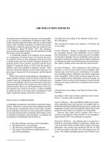
The general subject of treatment of oil spillage represents
a relatively new area of technology that is unique in that it
encompasses chemical, mechanical, and biological disciplines.
There are three major aspects to the problem of oil spills.
1) PREVENTION OF THE SPILL;
2) CONTAINMENT AND RECOVERY OF THE
SPILL;
3) TREATMENT OF THE SURFACE OIL.
Although this discussion is mainly directed toward the treat-
ment of the spilled oil, the related areas will also be considered
in order to put the overall subject in the correct perspective.
PREVENTION OF THE SPILL
The Prevention of Oil Spillages is the Primary
Consideration
It should be emphasized that prevention is the fi rst consid-
eration and, of course, the most complete solution. In the
industrial and governmental communities, the major effort
has been directed toward this area. There is extensive ongo-
ing research for example, ranging from operational areas
such as collision avoidance techniques and training to more
novel approaches such as the gellation of crude oil. In this
latter approach several chemical systems have been devel-
oped to gel the oil cargo. This in-situ solidifi cation thereby
prevents the release of oil from a damaged cargo compart-
ment that may be in danger of failure.
Details of this gellation system can be found in US Patent
3,634,050.
1
Other details, such as the effects of mixing, crude oil
type, chemical concentration, and so on, on the strength of the
gel have been outlined by Corino.
2
Gellation is a novel approach
to prevent the release of oil. However the fact that there have
been no commercial uses of this method since its conception
twenty fi ve years ago raises questions regarding its practicality.
Finally, the removal of the oil cargo from a grounded
tanker is another area where the threat of the release of a fl uid
and mobile oil cargo to the marine environment has been miti-
gated by advances in salvage techniques. The offl oading of
the grounded SS General Colocotronis on a reef off Eleuthera
Island in March–April 1969 and the well documented recov-
ery of Bunker C oil from the sunken tanker SS Arrow in
Chedabucto Bay, Nova Scotia during the winter of 1970
3
are
two outstanding examples of this prevention technique.
This latter incident represented a singular achievement
in light of the weather conditions encountered during early
March in Nova Scotia. Over 6000 tons of viscous Bunker C
oil were recovered from the sunken wreck. The salvage team
used a hot tap technique to penetrate the tanker cargo tanks
and then used a steam traced pumping system to transfer the
oil to a barge at the surface.
A more recent and massive removal of oil was the EXXON
VALDEZ in March 1989 after its grounding on a reef in Prince
William Sound. Although approx 250,000 Bbls of North
Slope Crude oil was spilled from the grounded vessel, 80 per-
cent of its cargo was still in the tanker. This offl oading was a
signifi cant marine engineering feat since care must be taken to
offl oad such a large vessel in the correct sequence since other-
wise hull stresses could cause the vessel to break up.
CONTAINMENT, RECOVERY OR REMOVAL OF THE
SPILLED OIL
If a spill has occurred, it is universally agreed that the rec-
ommended procedure is to contain and physically recover
it with or without the use of adsorbents. It is obviously the
most direct solution to spill incident, if conditions permit its
execution. This approach may entail three processes:
1) Confinement of the spill by spill booms.
2) Recovery of the spill by sorbing agents. In this
area, more recent advancements have been solidi-
fying agents (Solidifiers).
3) Physical removal of the contained oil by oil pickup
devices.
4) Controlled burning of spilled oil.
These aspects of the recovery approach are interrelated as
will be appreciated by the following discussion.
Confi nement of the Spill by Spill Booms There are many
oil spill booms commercially available today. Unfortunately
they are signifi cantly limited by the velocity of the surface
current and wave height. Although there are variations in
the materials of construction, strength, geometry, etc., of
these various boom designs, as evidenced by the number
available and the range of costs, their general forms are
quite similar. Almost any type of fl oating barrier will hold
back and contain some amount of oil under quiescent
C015_002_r03.indd 802C015_002_r03.indd 802 11/18/2005 10:56:37 AM11/18/2005 10:56:37 AM
© 2006 by Taylor & Francis Group, LLC
OIL SPILLAGE INTO WATER—TREATMENT 803
conditions. Indeed, telephone poles have been employed in
more than one spill instance as a jury rig emergency mea-
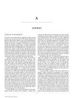
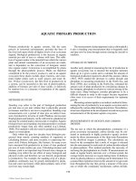
sure. To improve the capacity of such a fl oating barrier, a
weighted skirt is hung from the fl otating member illustrated
in Figure 1. Design requirements for spill booms have been
published by Lehr and Scherer
4
and Hoult,
5
among others.
By a rather cursory inspection of Figure 1, we may now
appreciate some of these requirements such as:
Suffi cient freeboard to prevent overtopping by waves;
Adequate skirt length below water surface to confi ned a
suffi cient quantity of oil;
Adequate fl exibility to permit the boom to bend under
wave action and maintain its retention of the oil spill;
Suffi cient mechanical strength to withstand the forces
imposed by the environment.
Some of the diffi culties of oil retention against the action
of a steady current are illustrated in Figure 1. A discussion
of draw down phenomena by Hoult
6
outlines that a gradient
in oil thickness, h, is established by the stress imposed by
the current fl ow. There is, based on the fl uid dynamics of
the contained volume of oil in the presence of a water cur-
rent, a limiting water velocity above which oil droplets are
entrained and fl ow underneath the barrier.
The deployment of the above described mechanical
booms is also an important consideration. In the event of a
spill, the speed of response is, of course, most critical. Hence,
Flotation
Member
Water
Oil Contained Under
Quiescent Conditions
Oil Containment
Capability Improved
Draw Down Due To
Water Current
Flotation
Member
Water
Weighted
Skirt
Oil
Oil
FIGURE 1 Mechanical boom principle.
C015_002_r03.indd 803C015_002_r03.indd 803 11/18/2005 10:56:37 AM11/18/2005 10:56:37 AM
© 2006 by Taylor & Francis Group, LLC
804 OIL SPILLAGE INTO WATER—TREATMENT
easily deployed lightweight booms are desirable. However,
these desired properties are not necessarily consistent with
making booms stronger and more capable of withstanding
severe sea conditions.
These are the criteria and mechanism of operation of oil
spill booms. It is beyond the scope of this chapter to present
the many commercial and changing commercial products.
In the world Catalog of Oil Spill Response Products, booms
have been divided into three categories based on maximum
operating signifi cant wave height (Hs). Table 1 shows the
ranges of freeboard and draft corresponding to the expected
maximum waves. A boom size can thus be selected based on
the expected environment.
In the World Catalog of Oil Spill Response Products,
booms have been divided into three categories based on
maximum operating signifi cant wave height (Hs). Table 1
shows the ranges of freeboard and draft corresponding to the
expected maximum waves. A boom size can thus be selected
based on the expected environment.
Boom Selection Matrix The selection of a boom depends on
how rapidly it is needed and how readily it can be utilized.
Deployment speed and ease relate to the number of people,
the amount of time, and any special equipment (Winches,
etc.—even wrenches) necessary to move the required amount
of boom from storage to the launch site, to deploy it, and to
position it around the spill. For example, self-infl atable booms
can be deployed very rapidly either from reels or bundles.
Experience has shown, however, that this rapid response boom
should be replaced by a more rugged boom if extended deploy-
ment is required. Thus, deployment ease must often be traded
off against ruggedness and durability.
The matrix sho
optimum boom for a specifi c application since it indicates:
• Generic types of boom that are most suitable in a
given environment
• Selected booms that have the most needed perfor-
mance characteristics
• Choices with the most desirable convenience
features.
Excess or reserve buoyancy is the surplus of fl otation over
boom weight as deployed, and is a measure of resistance
to boom submergence. Wave response is a measure of con-
formance to the water surface and is usually improved by
increasing boom water-plane area and fl exibility. Other char-
acteristics should be evident from the headings.
To use the matrix correctly, follow these steps:
1. Identify the most probable environmental condi-
tions in which the boom will be used. Note those
types of booms with an acceptable rating (1 or 2).
2. Identify the most needed performance charac-
teristics for the intended application. From the
booms chosen above, select the ones that have an
acceptable rating (1 or 2) in the most important
performance characteristics.
3. Identify the most desirable convenience features.
With booms from steps 1 and 2 above, select the
boom with the best rating in the convenience fea-
tures of interest.
These data (T
permission of EXXON from a very informative OIL SPILL
RESPONSE FIELD MANUAL by Exxon Production
Research Company published in 1992.
Recovery of the Spill by Sorbing Agents A most direct
manner of physically removing the spilled oil is by use
of sorbents. These materials are buoyant, and preferen-
tially wetted by and adsorb oil. In essence, they permit
this sorbed oil to be physically “picked up” from the water.
In addition to making the collection of oil an easier task,
the oil is prevented from spreading and remains as a more
congealed mass.
Materials that have been found useful for this service vary
from simple, naturally occurring materials such as straw, saw-
dust, and peat to synthetic agents, such as polyurethane foam
and polystyrene powder. The oil pickup capability varies
greatly. For example, values of oil pickup, i.e., weight of oil
sorbed per weight of adsorption material, have been reported
by Struzeski and Dewling
7
for straw as 3 to 5, although higher
values have been reported. Polyurethane foam, by comparison,
is capable of oil pick up values of 80. A complete investiga-
tion of sorbents for oil spill removal has been published by
Schatzberg and Nagy.
8
Of interest is the variation in the oil
pickup capability of a given sorbent based on the type of
spilled oil. For example, in Schatzberg’s controlled tests, oil
pickup by straw was 6.4 for heavy crude oil and 2.4 for light
crude oil. For urea formaldehyde foam, however, oil pickup
was 52.4 for heavy crude and 50.3 for light crude. Also some
TABLE 1
Boom Classification
Environment
Hs Maximum Freeboard Draft
ft meters inches centimeters inches centimeters
Calm Water 1 0.3 4–10 10–25 6–12 15–30
Harbor 3 0.9 10–18 25–46 12–24 30–61
Offshore 6 1.8 Ͼ18 Ͼ46 Ͼ24 Ͼ61
C015_002_r03.indd 804C015_002_r03.indd 804 11/18/2005 10:56:38 AM11/18/2005 10:56:38 AM
© 2006 by Taylor & Francis Group, LLC
wn in Table 2 can be used to select the
able 1 and 2) were extracted and used with the
OIL SPILLAGE INTO WATER—TREATMENT 805
TABLE 2
Boom Selection Matrix
Legend
1—Good
2—Fair
3—Poor
Type of Boom
Internal Foam
Flotation Self-Inflatable Pressure-Inflatable
External Tension
Member Fence
Environmental Offshore
Conditions Hs Ͼ 3 ft; 2 2 1 1 3
V Ͼ 1 kt — — — — —
Harbor — — — — —
Hs Ͻ 3 ft; 1 1 1 2 2
V Ͻ 1 kt — — — — —
Calm Water — — — — —
Hs Ͻ 1 ft; 1 1 1 2 1
V Ͻ .5 kt — —
High Currents — — — — —
V Ͼ 1 kt 2* 3 2 1 3
Shallow Water — —
(Depth Ͻ 1 ft) 1 2 2 3 3
Performance Operation 1 3 2 3 2
Characteristics in Debris — — — — —
Excess 2 1 1 2 3
Buoyancy — — — — —
Wave 2 2 1 1 3
Response — — — — —
Strength 2 3 1 1 1
Convenience Ease of 2 1 2 3 2
Characteristics Handling — — — — —
Ease of 1 1 1 3 1
Cleaning — — — — —
Compactability 3 1 1 2 3
Cost/Ft — — — — —
1—Low — — — — —
2—Medium 1 3 2 3 2
3—High — — — — —
Notes:
* Hs ϭ Significant Wave Height.
* V ϭ Velocity of Surface Current.
Not all the booms of a particular generic type have the rating shown in the matrix. But at least one or more commercially available booms of the generic
type in question have the rating shown.
* Specially-designed high-current models may be available (river boom).
C015_002_r03.indd 805C015_002_r03.indd 805 11/18/2005 10:56:38 AM11/18/2005 10:56:38 AM
© 2006 by Taylor & Francis Group, LLC
806 OIL SPILLAGE INTO WATER—TREATMENT
sorbents are much less effective for oil adsorption if contacted
by water prior to application to the spill.
Although highly effective sorbents are available as
noted above, techniques for harvesting (recovering) the oil
soaked sorbent have been limiting. For example, there have
been prior instances of oil soaked straw recovery by manual
pickup with pitchforks. However, there is development
work underway to mechanize this step as well as the appli-
cation procedure. In this regard, some very practical obser-
vations on the use of sorbents have been made by an IMCO
subcommittee on Marine Pollution. This guidance manual
outlined that “the use
9
of absorbents involves six basic oper-
ations, the supply, storage, and transportation of the mate-
rial and then the application, harvesting and disposal of the
contaminated absorbent.” The manual further observes that
some of the early applications of sorbents such as the Torrey
Canyon and Santa Barbara suffered because of the lack of
effective and effi cient harvesting techniques.
More recently, since the early 1990s a new approach to
oil pickup was conceived by the use of SOLIDIFIERS.
Solidifi ers are products which, when mixed with oil,
turn the oil into a coherent mass. They are usually available
in dry granular form. Unlike sorbents that physically soak
up liquid, solidifi ers bond the liquid into a solid carpet-like
mass with minimal volume increase, and retain the liquid for
easy removal. The bonded material also eliminates dripping-
sponge effect by not allowing the material to be squeezed
out, minimizing residue or contamination. Some polymers,
in suffi cient quantity or of high molecular weight, can actu-
ally convert the oil to a rubber-like substance.
Solidifi ers are most commonly used during very small
oil spills on land or restricted waterways to immobilize
the oil and enhance manual recovery. There has been little
documented use of solidifi ers on large spills or open water.
However, the possibility that they may reduce the spread of
waterborne oil by solidifying it and increase recovery and
removal rates is a concept with signifi cant potential benefi t.
The effectiveness of a solidifi er is based on the amount
of product and time it takes to “fi x” a given volume of oil.
The less effective products require larger amounts to solidify
oil. Fingas et al. (1994) presented results from effectiveness
tests on various solidifi ers and found that generally between
13–44 percent by weight of the product to oil was required to
solidify Alberta Sweet Crude over a 30-minute period.
The entire treatment of solidifi ers as an aid to oil spill
response is well covered in an MSRC publication.
10
Physical Removal of the Contained Oil by Oil Pickup
Devices Since oil containment booms have a fi xed capacity
for oil spill containment, it is important to consider means
to physically remove the contained oil from the surface. The
use of sorbents has been discussed. An alternate approach is
to remove the fl uid oil by means of skimming devices.
Oil skimmers have been divided into fi ve categories:
11
• Oleophilic surfaces (belts, disc, ropes, and
brushes, either acting independently, mounted on
a vessel or used in combination with a boom)
• Weirs (simple, self-leveling, vortex assisted, auger
assisted, vessel-mounted, and weir/boom systems)
• Vacuum units (portable units and truck-mounted
units)
• Hydrodynamic devices (hydrocyclone and water
jet types)
• Other methods (including paddle belt and net
trawl).
The selection of the optimum skimmer for a particular
spill is based on site conditions such as the sea state and
characteristics of the spilled oil e.g. viscosity and emulsion-
forming tendency.
There are over 100 commercially available skimmers
on the market that fall within the generic types previously
mentioned. These are summarized in publications such
as the WORLD CATALOG OF OIL SPILL RESPONSE
PRODUCTS.
For example, for the principle of oleophilic surfaces,
these can comprise either a sorbent belt, an oleophilic rope
or a solid oleophilic disc that rotates through the surface oil
fi lm. In heavy sea conditions this type would be more effec-
tive than a wier type that is more suited to protected in-shore
areas.
Controlled Burning of the Spilled Oil Burning represents
a surface treatment of an oil spill that is attractive in that the
oil is essentially removed from the water. However, some
of the negative aspects of this approach that have hampered
its widespread acceptance and use may be summarized as
follows:
In many spill instances, there is an obvious concern
regarding the combustion of the oil for safety reasons. Spills
near harbors, tankers, offshore platforms would create an
obvious hazard if set afi re.
A minimum thickness of oil is required to establish
combustion.
Air pollution is a concern in some instances. There is
continuing evaluation and development burning of agents.
As reported by Alan Allen,
12
there are fi re retardant
booms and ignition methods available to burn the oil under
proper conditions e.g. oil fi lm thickness and amount of emul-
sifi ed water in the oil. An effective burn after the EXXON
VALDEZ spill on Sat. March 25, 1989 was reported by Allen
in this publication.
The very encouraging burn rate statistics suggest that
only 2% of the original relatively fresh oil remained as
residue.
In this regard, it is relevant to quote the author of this
publication in its entirety because of its concise and suffi -
cient analysis of this technique by one well recognized in
this method.
“It should be recognized that the elimination of spilled oil
using in-situ burning must be considered in light of the full
range of potential impacts (safety, air quality, etc.) associated
with the burning of oil an water. The mechanical removal of
spilled oil is by far the preferred cleanup technique whenever
possible. Burning, on the other hand, may provide a safe,
C015_002_r03.indd 806C015_002_r03.indd 806 11/18/2005 10:56:38 AM11/18/2005 10:56:38 AM
© 2006 by Taylor & Francis Group, LLC
OIL SPILLAGE INTO WATER—TREATMENT 807
effi cient and logistically simple method for eliminating oil
under certain conditions. As a backup for mechanical cleanup
techniques, in-situ burning can provide a useful means of elim-
inating large quantities of oil quickly, while avoiding the need
for recovered oil storage containers. Anyone considering the
use of burning should be sure that all regulatory controls have
been satisfi ed, that the ignition and burning operations can be
carried out safety, and that the temporary reductions in local air
quality represent the lower of all other environmental impacts
should the spilled oil not be burned.”
TREATMENT OF THE SURFACE OIL
Chemical Treatment of Surface Oil Should Be
Considered as an Alternate Solution
It is generally agreed, as indicated above, that situations can
arise where the spill cannot be contained and recovered because
sea conditions, weather state, and so on, are beyond the cur-
rent operating capability of containment devices. There are
also instances wherein the logistics of containment and recov-
ery equipment, that is, containment boom availability and/or
deployment time and effort, could indicate chemical treatment
as the most practical and expedient handling technique. When
physical recovery of the oil pollutant is impractical, there are,
in effect, two courses of action possible. In one case, the oil
may be permitted to remain as intact cohesive slick on the
surface of the water and possibly reach shore. The alternate
course is to “treat” this surface oil—such treatment essentially
directed toward the removal of the oil from the water surface
and the enhancement of its ultimate removal from the environ-
ment. This many be accomplished by chemical dispersion.
The Ecological and Economic Damage Caused by an
Untreated Oil Spill Can Be Extensive
The damage resulting from an untreated oil spill is both visu-
ally apparent and extensive. It encompasses both biological
as well as property damage. The potential damage may be
summarized as follows:
Marine fowl, particularly diving birds, are particularly
vulnerable to an oil spill. As reported by Nelson-Smith,
13
sea birds are most obvious victims of an oil spill due to
“mechanical damage.” The oil penetrates and clogs the
plumage which the bird depends upon for waterproofi ng and
heat insulation. For example, a duck with oil-impregnated
plumage is under the same stress at a moderate temperature
of ϩ59ЊF as a normal bird would be under a more severe
temperature condition at −4ЊF. Some statistics regarding bird
damage have been cited by McCaull.
14
More than 25,000
birds, mostly guillemots and razorbills, were killed after the
Torrey Canyon grounding. The guillemot casualties equaled
the entire breeding stock between the Isle of Wright and
Cardigan Bay. Bird losses in the Santa Barbara spill, accord-
ing to the state Department of Fish and Game, totaled 3500.
Shore contamination by beached oil represents biologi-
cal, as well as property damage. The tendency of oil to cling
to shore surfaces, such as beach sand, sea walls, and the resul-
tant property damage, are well established. This is perhaps
the most apparent and widely publicized damaging aspect as
attested by lawsuits on the part of tourist interests, property
owners, etc. There is also, in a biological sense, a physical
smothering effect on some attached, intertidal organisms
such as mussels and barnacles. The effects of untreated oil
coming ashore is well illustrated by Blumer et al.
15
regarding
a No. 2 diesel fuel spill from the barge Florida in Buzzards
Bay, Massachusetts in September 1969. Oil was incorpo-
rated into the bottom sediment to at least 10 meters of water
depth, testifying to the wetting effect of untreated oil in
this instance, the oil was physically dispersed by the heavy
seas but retained its adhesive characteristics. Therefore, it
is deduced that the oil droplets probably came into contact
with and wetted and upswept, suspended particulates which
later settled again to the bottom. Other spill instances depict-
ing the importance of this aspect that of the incorporation of
oil into the sediment-have been reported by Murphy.
16
In the
Buzzards Bay and several other spill incidents of distillate
fuels cited by Murphy, there has been a signifi cant kill of all
marine life in the area since these highly aromatic products
are known to be much more toxic than whole crude oil.
Persistent tarry agglomerates are formed as the spilled oil
weathers at sea. There has been increasing attention directed
to the presence of tar-like globules ranging up to 10 cm in
diameter in the open sea. As reported by Baker
17
during the
voyage of Thor Heyerdahl’s papyrus boat, Ra, during fi ve
separate days, they sailed through masses of these agglomer-
ates whose age could be substantiated by the growth of goose
barnacles adhering to them. There have been other inci-
dents reported recently by the International Oceanographic
Foundation
18
and a well documented survey was made by
the research craft, R.V. Atlantis, as reported by Horn et al.
19
In this latter investigation, tarry agglomerates were present
in 75% of over 700 hauls with a surface skimming (neuston)
net in the Mediterranean Sea and eastern North Atlantic. The
amount of tar in some areas was estimated at 0.5 milliliter in
volume per square meter of sea surface.
The Behavior of Spilled Oil at Sea
Before consideration of the mechanism of dispersing oil and
its associated effects, an understanding of the behavior of
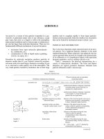
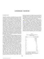
spilled oil at sea will be useful. When a volume of oil is
spilled onto the surface of water, the oil has a driving force
to fi lm out or spread-in essence, a spreading pressure usually
expressed as a Spreading Coeffi cient. This Spreading S
o/w
,
is readily quantifi ed and is determined by a balance of the
surface tension forces as follows.
S
o/w w o/w o,
ϭϪ Ϫgg g
(1)
wherein:
S
o/w
is the spreading coeffi cient for oil on water
ergs/cm
2
or dynes/cm
C015_002_r03.indd 807C015_002_r03.indd 807 11/18/2005 10:56:38 AM11/18/2005 10:56:38 AM
© 2006 by Taylor & Francis Group, LLC
808 OIL SPILLAGE INTO WATER—TREATMENT
γ
γ
γ
γγγ
o
w
o/w
s
o/w
Water
Oil
s
o/w
, Spreading Coefficient For Oil On Water,
=
Measured Value For Kuwait Crude Oil On Sea Water
s
o/w
= 61 - 28 - 22
= 11 Dynes/cm
w o o/w
-
-
FIGURE 2 The spreading behavior of spilled oil.
Film Thickness
Inches x 10
–6
Appearance
Of Film
Approx.
Gals./Sq. Mile
1.5
Barely Visible
25
3.0
Silver Sheen
50
6.0
First Trace Of Color
100
12.0
Bright Bands Of Color
200
80.0+
Dark Colors
1330+
Oil
Spill
Water
Column
FIGURE 3 Oil slick appearance during spreading.
C015_002_r03.indd 808C015_002_r03.indd 808 11/18/2005 10:56:38 AM11/18/2005 10:56:38 AM
© 2006 by Taylor & Francis Group, LLC
OIL SPILLAGE INTO WATER—TREATMENT 809
g
w
is surface tension of water, dynes/cm
g
o
is surface tension of oil, dynes/cm
g
o/w
interfacial tension of oil and water, dynes/cm.
By an e
it can be seen that if S
o/w
—the resultant spreading force
is positive, the oil will spread on the water; if negative, it
will not spread but remain a “lens” of Liquid. For exam-
ple, spreading coeffi cient values for Kuwait Crude on sea
water, reported by Canevari
20
are positive and confi rm that
for this system the oil readily spreads on the water phase.
Garrett
21
has summarized spreading pressures of vari-
ous oils on sea water that vary from 25 to 33 dynes/cm.
Cochran
22
has also published values that generally agree
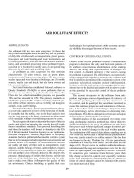
for positive spreading coeffi cients, the oil is capable of
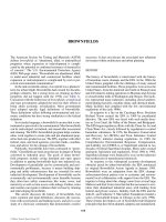
fi lming out to very thin fi lms. A fi lm thickness of only
3.0 ϫ 10
−6
inches representing a spill of 50 gallons of oil
distributed over a surface area of one mile will be quite
visible as a “fl at” silver sheen on the surface of the water.
However, the initial spreading rate of a large volume
of spilled oil is based on the volume and density of the oil
in essence, sort of static head that overcomes other factors
such as interfacial tension.
The Mechanism of Dispersing Surface Oil Slicks by
Chemical Dispersants
The dispersion of surface oil fi lms as fi ne oil droplets into
the water column is promoted by the use of a chemical dis-
persant. This oil spill dispersant consists primarily of a surface
active agent (surfactant) and a solvent. The solvent is added
as a diluent or vehicle for the surfactant. It also reduces the
viscosity and aids in the uniform distribution of the surfac-
tant to the oil fi lm.
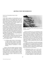
A surfactant is a compound that actually contains both
water compatible (hydrophilic) and oil compatible (lipophilic)
groups. Due to this amphiphatic nature, a surfactant locates and
arranges itself at an oil–water interface as schematically shown
in Figure 4. The surfactant’s molecular structure, e.g. ratio of
hydrophilic to lipophilic portion, determines the type of disper-
sion (oil droplets dispersed in water phase or water droplets
dispersed in oil phase), as well as stability of the dispersion. In
essence, a surfactant that is principally water soluble disperses
oil-in-water and established water as the continuous phase; a
surfactant that is principally oil soluble, the converse. This is
Bancroft’s Law,
23
which has been tested and proven empiri-
cally true over the years. A convenient classifi cation for sur-
factants therefore, is based on the ratio or balance of the water
FIGURE 4 Influences of surfactant structure on type of dispersion.
HYDROPHILIC-LIPOPHILIC BALANCE (HLB)
SCHEMATIC OF
SURFACTANT
TYPE OF
EMULSION
FORMED
DISPERSE
WATER
DROPLETS
DISPERSE
OIL DROPLETS
WATER
OIL
1
51015
20
Increase In
Oil Solubility
Increase In
Water Solubility
Hydrophilic Group
(Water Compatable)
Lipophilic Group
(Oil Compatable)
Oil Soluble Surfactant
Favors Water-In-Oil
Dispersion
Water Soluble Surfactant
Favors Oil-In-Water
Dispersion
C015_002_r03.indd 809C015_002_r03.indd 809 11/18/2005 10:56:39 AM11/18/2005 10:56:39 AM
© 2006 by Taylor & Francis Group, LLC
xamination of the force balance shown in Figure 2
with these level on sea water. As one can see from Figure 3,
810 OIL SPILLAGE INTO WATER—TREATMENT
compatible portion to the oil compatible portion-sometimes
referred to as HLB (Hydrophilic–Lipophilic Balance).
24
This relationship between the molecular structure of the
the physical concept behind Bancroft’s Law may be appreci-
ated. For example, it can be visualized that for a more water
compatible surfactant, the physical location of the larger
hydrophilic group on the outside of the dispersed oil drop-
lets results in a more effective “fender” to parry droplet colli-
sions and prevent droplet coalescence. The converse, location
and the larger portion of the surfactant in the dispersed rather
than the continuous phase, would be geometrically awkward
and unstable.
25
The mechanism of oil slick dispersion by the
application of chemical dispersants has been covered in some
detail by Poliakoff
26
and Canevari,
27,28,29
among others. From
the above discussion, one can see that the chemical disper-
sant (surfactant) will locate at the oil–water interfaced reduce
interfacial tension. This will then act to increase the spreading
tendency of the oil fi lm as shown by Eq. (1). More important,
it promotes fi ne droplet formation which can be expressed as:
WA
ko/wo/w
ϭ g
,
,
(2)
where:
W k mixing energy, ergs
A
o/w
interfacial area, cm
2
γ
o/w
interfacial tension, dynes/cm.
Thus, for the same amount of mixing energy, a reduction of
γ
o/w
will result in a corresponding increase in A
o/w
.
It is important to emphasize that, as can be realized from
the above discussion, the chemically dispersed oil does not
sink. Rather, the surfactant merely enhances small droplet
formation for a given amount of mixing energy. Smaller
diameter oil droplets have a much lower rise velocity per
the familiar Stokes Law. Hence, once the oil is chemically
treated, and placed 3 to 5 feet below the surface of the water
by the mixing process, it does not rise to the surface as read-
There are many surfactants that will aid the formation
of fi ne droplets in the above manner. It has already been
noted that the surfactant structure (Hydrophilic–Lipophilic
Balance) infl uences the effi ciency of the emulsifi er.
However, a more subtle and less tractable requirement
for an effective dispersant is the prevention of droplet
coalescence once the fi ne oil droplets are formed. This is
dispersed by a chemical surfactant and maintained in sus-
pension by gentle bubbling of air. After 24 hours, there has
been no coalescence or separation of these fi ne oil drop-
lets. In the control sample, with similar volume of oil and
mixing energy, the oil separated almost immediately and
reformed an intact, cohesive fi lm of oil.
In essence then, an effective dispersant must parry drop-
let collisions physically. For example, dispersed oil may
separate in a sample bottle but even though there may be
a “creaming” effect, i.e. oil droplets concentrate near the
surface, the droplets should not coalesce to reform an intact
slick. It is this same “fendering” action that reduces the ten-
dency of the droplets to stick to a solid surface.
The Physical and Environmental Incentives for
Dispersing Oil Slicks
Consideration of the previous summary of the potential
damaging aspects of an untreated and unrecoverable oil spill
indicates that the removal of the intact, cohesive mass of oil
from the surface of the water yields more than a cosmetic
effect as is often claimed. For this alternate approach when
conditions do not permit the recovery of the spilled oil, the
removal of oil from the surface by dispersing it into fi ne
droplets yields established benefi ts that can be summarized
by the following discussion:
1) Oil properly dispersed with a chemical dispersant
will not stick to a solid surface. As previously out-
lined, the physical fending action of a properly
selected surface-active agent prevents the oil drop-
lets from coalescing after dispersion. This same
property also inhibits the oil from wetting out on
a solid surface. This has become a controversial
point and it has actually been claimed that the con-
verse is true. For example, in the First Report of the
President’s Panel on Oil Spills,
30
it has been stated
that such agents cause the oil to “spread into the
sand-surfaces which untreated oil would not wet.”
A laboratory experiment was conducted to evaluate
this aspect. A mixture of 256 cc of sea water, 95
cc of beach sand (New Jersey shore area), and 20
cc Kuwait Crude, were placed in a graduate. This
represented a vertical cross section of the marine
environment after an oil spill. The mixture was then
agitated to simulate the possible contact of sedi-
ment by the oil when turbulent conditions existed.
After mixing, the sample was settled to separate the
oil–sand water phases. In a body of water, either the
oil may be driven down into contact with the sandy
bottom or the sand may be suspended in the body
of water by wave action, such as deduced from the
previously cited Buzzards Bay spill. The graduate
was then purged with clean water to simulate the
return of the environment to a non-contaminated
condition.
The experiment was then repeated using 20 cc
of Kuwait Crude Oil and 4 cc of a chemical dis-
persant (5 parts oil/1 part dispersant).
Virtually no “treated” oil impregnated the sand.
For the experiment with the untreated crude oil, an
analysis of the oil content of the sand bed indicated
that 11.20 cc of oil remained of the initial 20 cc.
2) Oil removed from surface water prevents bird
damage. The aforementioned hazard to marine
fowl that is presented by the surface oil film is
C015_002_r03.indd 810C015_002_r03.indd 810 11/18/2005 10:56:40 AM11/18/2005 10:56:40 AM
© 2006 by Taylor & Francis Group, LLC
surfactant and the emulsion type is also shown in Figure 4 and
ily, as illustrated by Figure 5.
illustrated by Figure 6 wherein a volume of oil has been
OIL SPILLAGE INTO WATER—TREATMENT 811
Oil Droplets
Dispersant
Dispersant Prevents Coalescence Of Droplets
FIGURE 6 Dispersant maintains oil droplets in suspension with mild agitation
a) Oil Spill
b) Dispersant Reduces Interfacial Tension
c) Agitation Readily Forms Oil Droplets
Mixing Prop
Water
Fine Oil
Droplets
Water Soluble
Oil Soluble
Water
Surfactant
Water
Oil
γ
γ
γ
o
w
o/w
s
o/w
FIGURE 5 Dispersant enhances droplet formation.
C015_002_r03.indd 811C015_002_r03.indd 811 11/18/2005 10:56:40 AM11/18/2005 10:56:40 AM
© 2006 by Taylor & Francis Group, LLC
812 OIL SPILLAGE INTO WATER—TREATMENT
clearly eliminated when the oil is dispersed as fine
droplets into the water column. These dispersed
droplets are placed several feet below the water
surface by the mixing process.
3) The fire hazard from the spilled oil is reduced by
dispersion of the oil several feet into the water
column. The removal of this combustible material
from the water’s surface and from contact with
the atmosphere prevent possible combustion of
the spilled oil. This is perhaps the most accepted
benefit accruing from the use of dispersants. It has
provided the motivation for many past instances
of dispersant applications.
4) The rate of biodegradation of the oil is enhanced.
This is the historical basis for the dispersion
of oil. It is perhaps the most significant contri-
bution of dispersants. The order of magnitude
increases in interfacial area that are generated
by the dispersant greatly increases the rate of
biodegradation of the oil. ZoBell
31
has reported
biodegradation rates that are one or two orders
of magnitude higher in laboratory experiments
in which the oil is emulsified. Not only is the
physical state of the oil, that is, small droplets,
more conducive to bacterial action, but it is also
made available to a much larger population of
microbial organisms. This particular reference
has been one of the most complete treatments of
the subject of oil biodegradation to date.
A study by Robichaux and Myrick
32
presented
the results of a study of the effects of chemi-
cal dispersing agents on the rate of microbial
destruction of crude oil in aqueous environ-
ments. Increased destruction rates of up to 15
times the rate of untreated oil/water mixtures
were reported.
5) The formation of persistent tar lumps from an
untreated oil spill is prevented. The tarry ag-
glomerates (up to 10 cc dia.) found on the ocean
surface, as mentioned previously represent a
small percent residue of the crude oil. If the
crude oil had been dispersed into 10 µ to 1 mm
diameter droplets, these large residue agglom-
erates would not have formed and their persis-
tence in the marine environment would have
been greatly reduced.
The Concern Regarding the Chemical Dispersion of
Oil Spills
Clearly then, from a consideration of the foregoing, the
removal of oil from the surface of the sea has merits in miti-
gating the damage resulting from a spill. It is more than a
cosmetic, hide-it-from view effect. What then are the nega-
tive aspects to their use? What is the ecological price for
introducing the chemical dispersant and dispersed oil into
the water column?
The major concern regarding the use of dispersants are
twofold as covered in the following discussion.
The Toxic Effects of the Chemical Dispersants
This has been an area of great concern since their use has
become signifi cant. There is a basis for this concern. It was
highlighted by the investigation by Smith et al. ,
33
after the
Torrey Canyon that indicated that in some areas, particularly
in the intertidal zone, the chemicals used were more toxic to
the marine life than the oil itself.
During this period (1967–1968), the chemical formula-
tions available to disperse spilled oil were derived mainly
from cleaning agents, hence the term “detergent” was used
quite commonly. To permit these agents to dissolve tar-like
residues and perform their cleaning function, an aromatic
solvent, such as heavy aromatic naphtha, was generally
employed. The short term acute toxicity of aromatic hydro-
carbon to marine life is well-known. Blumer
34
states that low
boiling aromatics are toxic to man as well as all other organ-
isms and that it was the great tragedy of the Torrey Canyon
that the detergents used were dissolved low boiling aromat-
ics. The Toxicity of these aromatic solvent constituents were
extensively studied by the Marine Biological Laboratory
of the UK. Their acute toxicity was evident since 5 ppm of
kerosene extract solvent killed 50% of the Elminius nauplius
larvae in 21 minutes. Their analyses of the more common
detergents (dispersants) used during the Torrey Canyon indi-
cated that they contained some portion of aromatics.
In addition to these toxic aromatic solvents, the surfactants
were typically selected from the class compounds formed by
the reaction of hydroxy-containing compounds (e.g. phenol or
alcohol) with ethylene oxide. A typical surfactant might be eth-
oxylated nonylphenol. The number of ethylene oxide groups
added to the nonylphenol hydro-phobe may be controlled to
any desired extent to adjust the degree of water solubility of the
material. These types of surfactants, although effective emulsi-
fi ers, were quite detrimental to marine life.
However, there has been research directed toward formu-
lating dispersants that would have little effect on marine life.
For example, water is now used as the solvent in products
where it is compatible with the particular surfactants. High
boiling saturated hydrocarbons which are similar to the type
of hydrocarbon that occur naturally in the marine environ-
ment have a low order of toxicity and are also employed as
solvents in some of the more recent dispersants. This modi-
fi cation of the solvent, and the selection of generic types of
surface-active agents that are not considered to be chemi-
cally toxic, have resulted in the development of dispersants
that have greatly reduced toxicity. This can be illustrated by
the study of J.E. Portmann,
35
example, three dispersant products used during the Torrey
Canyon spill and identifi ed as Torrey Canyon Dispersants
A, B, C, have 48 hr LC
50
values of 8.8, 5.8, and 6.6 ppm,
respectively. These concentrations represent the amount of
the specifi c agent to kill 50% of the test species (Crangon
crangon) in 48 hours. The toxicity of a typical Torrey Canyon
surfactant, ethoxylated nonlphenol is shown at 89.5 ppm. By
C015_002_r03.indd 812C015_002_r03.indd 812 11/18/2005 10:56:41 AM11/18/2005 10:56:41 AM
© 2006 by Taylor & Francis Group, LLC
summarized in Table 3. For
OIL SPILLAGE INTO WATER—TREATMENT 813
comparison, the Toxicity levels of three dispersant products
developed since the Torrey Canyon, identifi ed as Post Torrey
Canyon, Dispersants D, E, F, are 7500–10,000; 3300–10,000;
and >3300 ppm, respectively. These concentrations are
orders of magnitude greater than the level applied by con-
ventional application in the fi eld.
Other agencies have confi rmed this fi nding. Table
4 illustrates results of a recent study by the Fisheries
Research Board of Canada entitled, “Toxicity Tests with
Oil Dispersants in Connection with Oil Spill at Chedabucto
Bay N.S.”
36
Again, the large difference in toxicity due to
the surfactant-solvent recipe can be noted in the sum-
mary of results (Table 4). These values represent 4 day
LC
50
values in fresh water to Salmon (Salmo salar L) and
vary from “Toxic” (1–100 ppm) to “Practically non-toxic”
(>10,000 ppm). Over 25 research institutions are known
to have conducted studies on these lower toxicity chemi-
cals. Testing by Dr. Molly Spooner,
37,38
among others, has
encompassed juvenile species, planktonic life and other
very sensitive forms of marine life.
Clearly then, the concern and conclusion that all chemi-
cal dispersants are in themselves inherently toxic is incor-
rect. Some of the most effective emulsifi ers/dispersants
available are those derived from and found in the natural
environment.
The Toxic Effects of the Dispersed Oil
When the surface fi lm of oil is dispersed several feet or
more into the water column, it is unfortunately made avail-
able to other forms of marine life in addition to the hydro-
carbonoxidizing bacteria. Necton and other fi ler feeder
many now come into contact with dispersed oil droplets
that they otherwise may have escaped as surface oil. This
is, effect, the “ecological price” for the cited benefi ts of
dispersing oil. There are published data on the acute tox-
icity levels of dispersed oil such as that from the State of
Michigan
39
presented as Table 5. This does indicate an
approximate tolerance level of a thousand ppm or more
for dispersed oil. It can also be noted that the toxicity of
the chemical is refl ected in the toxicity level of 1000 ppm
or so for dispersed oil, however it should be noted that
(1) it is unlikely that fi sh would remain in this inhospitable
environment for 96 hours and (2) the dispersed oil has a
driving force to dilute itself. Of greater concern than these
short term acute effects is the possibility that the fi nely
dispersed oil droplets represent a more subtle contaminant
and may cause long-range detrimental effects. However, it
should also be noted that crude oil is a natural rather than
man-synthesized material. Wheeler North
40
reported after
extensive research into several spill incidents, “Unlike
many of the products man liberates into the environment,
crude oil is a naturally occurring substance. From time to
time it appears on the earth’s crust by natural processes of
exudation.”
More Recent Dispersant Research Has Involved
Improvement in Effectiveness
The previous discussion regarding the dispersion mecha-
nism cited the need for mixing energy, W
k
. This is normally
supplied by means of a work boat applying the chemical.
However, consider the rate by which this work is accom-
plished by the boat’s wake and propeller. A typical work
boat may apply energy to swath 50 ft wide at a speed of
5 knots thereby only mixing 35 acres per hour of ocean.
TABLE 3
Development of low toxicity dispersants illustrated by Portmann Study
Chemical
48 hour LC
50
, ppm brown
shrimp (Crangon Crangon)
Torrey Canyon Dispersant “A” 8.8
Torrey Canyon Dispersant “B” 5.8
Torrey Canyon Dispersant “C” 6.6
Post Torrey Canyon Dispersant “D” 7,500–10,000
Post Torrey Canyon Dispersant “E” 3,300–10,000
Post Torrey Canyon Dispersant “F” 3,300
Nonyl Phenol-Ethylene Oxide 89.5
TABLE 5
Toxicity of dispersants with and without crude oil
Chemical 96 hour TLM, ppm Fathead minnow
(Pimephales promelas)
Dispersant A 5.6
Dispersant A ϩ oil 14.0
Dispersant B 14.0
Dispersant B ϩ oil 27.0
Dispersant C 25.0
Dispersant C ϩ oil 42.0
Dispersant D 32.0
Dispersant D ϩ oil 44.0
Dispersant E 56.0
Dispersant E ϩ oil 75.0
Dispersant F 3200
ϩ
Dispersant F ϩ oil 1800
ϩ
TABLE 4
Summary of Canadian Fish. Res. Bd. evaluation of 10 dispersants
Classification Numbers of dispersants
48 hour LC50, ppm
Salmon
(Salmo Salar L)
Toxic 8 1–100
Moderately toxic 1 100–1000
Slightly toxic 0 1000–10,000
Practically non toxic 1 Ͼ10,000
C015_002_r03.indd 813C015_002_r03.indd 813 11/18/2005 10:56:41 AM11/18/2005 10:56:41 AM
© 2006 by Taylor & Francis Group, LLC
814 OIL SPILLAGE INTO WATER—TREATMENT
Therefore, in recent years, research has been directed at
eliminating the need for the tedious, time consuming
mixing process.
In essence, a “self-mix” dispersant formulation has been
developed that requires essentially no energy to be applied
to the oil-water interface in order to generate a dispersion
of fi ne oil droplets. This has greatly enhanced the scope
and potential of chemical dispersion particularly for large
spills. For example, since mixing is no longer needed, aerial
application alone would be feasible. Some aircraft uniquely
adapted for this service, such as the canadiar CL-215, carries
1500 gallons of dispersant and covers 3000 acres per hour
based on a 150 knot speed and treated swath width of 150
feet. Extensive use has already been made of commercial
DC-4’s and DC-6’s for this purpose. A very novel devel-
opment of a load on tank and spray system for even larger
aircraft is now in place.
The Mechanism of More Recently Developed Self-Mix
Dispersants
The mechanism of the self-mix chemical dispersants goes
beyond the simple thesis represented by Eq. (2). In an ideal
no-mixing system true spontaneous emulsifi cation (or “self-
mixing”) is postulated to occur in the following manner. The
chemical surfactant formulation is made compatible with the
bulk oil. However, when the oil phase comes into contact
with a water boundary rather than air, part of the surfactant
Sea Water
Oil Layer
Application
A)
B)
C)
Diffusion
Oil Associated With
Self-Mix Dispersant
Transported Into
Water Phase
As Fine Droplets
FIGURE 7 Mechanism of self-mix dispersion.
C015_002_r03.indd 814C015_002_r03.indd 814 11/18/2005 10:56:41 AM11/18/2005 10:56:41 AM
© 2006 by Taylor & Francis Group, LLC
OIL SPILLAGE INTO WATER—TREATMENT 815
has a strong driving force to diffuse into the water phase.
In this transport process, a small amount of oil “associated”
with the surfactant is carried into the water phase. A continu-
ation of this process produces a series of fi ne oil droplets
migrating from the oil phase into the water phase as sche-
In the graphical presentation of Figure 7, the surfactant for-
mulation can be seen to be compatible with the crude oil phase
as shown in (A). However, due to the nature of the specifi c
compounds, there is a driving force for part of the formulation
of diffuse into the water phase when it contacts an oil/water
interface (B). During this diffusion, some oil associated with
the surfactant as fi ne oil droplets is carried along with the sur-
factant into the water column as shown in (C). In essence, a
three component system—oil ϩ water ϩ surfactant is formed
at the interface. As the surfactant diffuses into the water phase,
the associated oil is thrown out of solution.
The migration of the surfactant from the oil into the
water phase-in essence, the source of energy for spontaneous
emulsifi cation comes from the redistribution of materials. It
can be seen that for this system to work in the fi eld as an oil
slick dispersant, the surfactant must be brought into contact
with the oil phase initially.
It is also interesting to observe that as the surfactant dif-
fuses through the interface, a reduction in interfacial tension
occurs. Over the entire oil/water interface, there are dissimi-
lar values of interfacial tension due to the somewhat random
diffusion of the surfactant at varying sites along the interface.
Any difference in interfacial tension produces a spreading
pressure, II, which causes rapid movement of the interface.
This interfacial turbulence also aids in the dispersion of the
oil into the water phase.
Field Tests Support the Role of Chemical Dispersants
to Minimize Oil Spill Impact
In summary, there is an increased awareness and rec-
ognition that there is a role for chemical dispersants in
minimizing damage from oil spills. The improved effective-
ness afforded by the self-mix dispersant system has been
demonstrated.
Over the past 10 years, there have been a number of
major fi eld tests that have demonstrated under real life condi-
tions the effectiveness and biological safety of this approach.
These have been reviewed and summarized in a study by the
National Research Council.
41
In order to establish that the transient, rapidly diluting
concentrations of dispersed oil are not harmful, actual mea-
surements of the biological effects were made during several
controlled oil spills.
For examples, on August 19, 1981 a fi eld experiment was
carried out in Long Cove, Searsport, Maine, which simulated
the dispersal of oil slicks in the nearshore zone.
42
The object
of this experiment was to obtain quantitative information on
the fate and effects of dispersed and non-dispersed oil in the
nearshore area. An upper and lower intertidal sampling are
within a 60 × 100 meter test plot were exposed to dispersed
oil in water resulting from the discharge of 250 gallons of
oil premixed with 25 gallons of COREXIT 9527 dispersant.
Release of treated oil was around high-water slack tide on
the surface of the water. The maximum water depth over the
test areas was 3.5 meters. Untreated crude oil (250 gallons)
was released on an ebbing tide within a separate, boomed-
off 60 × 100 meter test plot. A third test plot served as an oil-
free reference plot. To evaluate the effects on the intertidal
infaunal community structure, chemical and biological anal-
yses were carried out concurrently throughout the pre- and
post-spill periods. The conclusions reached by the Bowdoin
College scientists are quoted as follows:
• No evidence of any adverse effects was observed
on infaunal community structure from the expo-
sure of intertidal sediments to dispersed oil under
real spill treatment conditions.
• There is clear evidence that the undispersed oil
treatment caused some mortality of a commer-
cially important bivalve and increased densities
of opportunistic polychaetes.
• The results seen in the test plot that received
untreated oil, are consistent with studies of real-
world oil spills.
REFERENCES
1. Corino, E.R., E.F. Broderick and G.P. Canevari, Method of gelling
tanker cargoes, US Patent 3,634,050. Issued January 11, 1992.
2. Corino, E.R., Chemical gelling agents and dispersants. Paper presented
to the Third Joint Meeting of the American Institute of Chemical
Engineers and Puerto Rican Institute of Chemical Engineers, May 20,
1970.
3. Department of US Navy, The recovery of bunker C fuel oil from the
sunken tanker, SS ARROW, Navships 0994–008–1010, March 1970.
4. Lehr, W.E. and J.O. Scheren, Jr., Design requirements for booms, Proc.
of API and FWPCA Joint Conference on Control of Oil Spills, NYC,
New York, December 1969.
5. Hoult, David P., Containment and collection devices for Oil slicks, Oil
on the Sea, Plenum Press, 1969.
6. Hoult, David P., Containment of Oil Spills by Physical and Air barriers,
paper presented on the Third Joint Meeting of the American Institute of
Chemical Engineers and the Puerto Rican Institute of Chemical Engi-
neers, May 20, 1970.
7. Struzeski, E.J., Jr. and R.T. Dewling, Chemical treatment of oil spills,
Proc. of API and FWPCA Joint Conference on Control of Oil Spills
NYC, December 15–17, 1969.
8. Schatzbertg, Paul and K.V. Nagy, Sorbents for oil spill removal. Proc.
of API and EPA Joint Conference on Prevention and Control of Oil
Spills, Washington, DC, June.
9. Subcommittee on Marine Pollution IMCO, National arrangements for
dealing with oil pollution preparation of a manual for the guidance of
governments, March 2, 1992.
10. Chemical Oil Spill Treating Agents MSRC. Technical Report Series
93–015, 1993.
11. Oil Spill Response Manual, Exxon Production Research Co. page 77,
1992.
12. Allen, Alan, Comparison of Response Options for Offshore Oil Spills,
11th Annual AMOP Seminar Vancouver British Columbia, June 7–9,
1988.
13. Nelson Smith, A., Effects of oil on plants and animals, Proc., Seminar
on Water Pollution by Oil, Aviemore, Scotland, May 4–8, 1970.
14. McCaull, Julian, The black tide, Environment, November 1969.
15. Blumer, M., G. Souza, and J. Sass, Hydrocarbon pollution edible shell-
fish by an oil spill, Marine Biology, 1970.
C015_002_r03.indd 815C015_002_r03.indd 815 11/18/2005 10:56:42 AM11/18/2005 10:56:42 AM
© 2006 by Taylor & Francis Group, LLC
matically shown by Figure 7.
816 OIL SPILLAGE INTO WATER—TREATMENT
16. Murphy, Thomas A., Environmental aspects of oil pollution, paper pre-
sented to the Session on Oil Pollution Control, ASCE, Boston, Mas-
sachusetts, July 13, 1970.
17. Baker, Norman, The life and death of the good ship RA, Sports Illus-
trated, April 20, 1970.
18. Sea Secrets. International Oceanographic Foundation, 14, No. 4, p. 2,
July–August 1970.
19. Horn, Michael H., John M. Teal, and Richard H. Backus, Petroleum
lumps on the surface of the sea, Science, 168, pp. 245–246, April 10,
1970.
20. Canevari, Gerard P., The role of chemical dispersants in oil cleanup, Oil
on the Sea, Plenum Press, 1969.
21. Garrett, William D., Confinement and control of oil pollution on water
with monomolecular surface films, Proc. of API and FWPCA Joint
Conference on Control of Oil Spills, NYC, NY, December 15–17,
1969.
22. Cochran, Robert A. and Paul R. Scott, The growth of oil slicks and
their control by surface chemical agents, J. Petroleum Technology,
July 1971.
23. Bancroft, W.D., J. Phys. Chem., 17, p. 501, 1913; 19, p. 275, 1915.
24. Becker, P., Emulsions: Theory and Practice, Reinhold Publishing Corp.,
NY, 1957.
25. Canevari, G.P., Some basic concepts regarding the separation of oily
water mixtures, ASLE Transactions, pp., 190–198, July 1968.
26. Poliakoff, M.Z., Oil dispersing chemicals, Water Pollution Control
Research Series ORD-3, Washington, DC, May 1969.
27. Canevari, Gerard P., The role of chemical dispersants in oil cleanup, Oil
on the Sea, Plenum Press, pp. 29–51, 1969.
28. Canevari, Gerard P., General dispersant theory, Proceedings of Joint
Conference on Prevention and Control of Oil Spills, API/FWQA, New
York City, New York, Dec. 1969.
29. Canevari, Gerard P., Oil spill dispersants-Current status and future out-
look, Proc. of API and EPA Joint Conference on Prevention and Con-
trol of Oil Spills, Washington, DC, June 15–17, 1971.
30. First Report of the President’s Panel on Oily Spills, Executive Office
of the President, Office of Science and Technology, Washington, DC,
1970.
31. ZoBell, Claude E., The occurrence, effects and fate of oil polluting the sea,
Int. Journal Air Water Pollution, pp. 173–198, Pergamon Press, 1963.
32. Robichaux, T.J. and H.N. Myrick, Chemical enhancement of the bio-
degradation of oil pollution, paper presented at the Offshore Technol-
ogy Conference, Dallas, Texas, April 19–21, 1971.
33. Smith, J.E., Torrey Canyon Pollution and Marine Life, Cambridge Uni-
versity Press, 1968.
34. Blumer, Max, The extent of marine oil pollution, Oil on the sea, Plenum
Press, pp. 29–51, 1969.
35. Portmann, J.E., The toxicity of 120 substances to marine organisms,
Fisheries Laboratory, Burnham-on-Crouch, Essex, England, September
1970.
36. Sprague, John B. and W.G. Carson, Toxicity tests with oil dispersants
in connection with oil spill at Chedabucto Bay, NS Fisheries Research
Board of Canada, St. Andrews, NB, 1970.
37. Spooner, M.F. and G. Malcolm Spooner, The problems of oil spills
at sea, Marine Biological Association of the UK. Plymouth, England
1968.
38. Spooner, M.F., Preliminary work on the comparative toxicities of some
oil spill dispersants and a few tests with oils and COREXIT, Marine
Biological Association of the UK, Plymouth, England 1968.
39. A biological evaluation of six chemicals used to disperse oil spills,
Department of Natural Resources, State of Michigan (1969).
40. Mitchell, Charles T., Einar K. Anderson, Lawrence G. Jones, and
Wheller J. North, What oil does to ecology, journal WPCE, 42, No. 5,
Part 1, May 1970, pp. 812–818.
41. Marine Board Commission on Engineering and Technical Systems
National Research Council. “Using on Spill Dispersant on the Sea”
National academy Press, 1989.
42. Gilfillan, E.S., D. Page, S.A. Hanson, J.C. Foster, J.R.P. Gelber, and
S.D. Pratt. 1983. Effect of spills of dispersed and non-dispersed oil on
intertidal infaunal community structure. Proc. 1983 Oil Spill Confer-
ence Washington, D.C: API. pp. 457–463.
GERARD P. CANEVARI
G.P. Canevari Associates
C015_002_r03.indd 816C015_002_r03.indd 816 11/18/2005 10:56:42 AM11/18/2005 10:56:42 AM
© 2006 by Taylor & Francis Group, LLC