ENCYCLOPEDIA OF ENVIRONMENTAL SCIENCE AND ENGINEERING - SMALL FLOW WASTEWATER TREATMENT TECHNOLOGY FOR DOMESTIC AND SPECIAL APPLICATIONS docx
Bạn đang xem bản rút gọn của tài liệu. Xem và tải ngay bản đầy đủ của tài liệu tại đây (1.09 MB, 12 trang )
1082
SMALL FLOW WASTEWATER TREATMENT TECHNOLOGY FOR
DOMESTIC AND SPECIAL APPLICATIONS
Recent concern regarding water pollution and general
worldwide public awareness of the problem associated with
pollution has resulted in increased pressures on all waste dis-
chargers to provide effective treatment and disposal of their
waste streams. Small subdivisions, motels, resorts, mobile
homes, watercraft, railroads, and the like, have not escaped
these pressures, although in many respects their total waste
contribution to the environment may be small. However, as
a result of the public awareness of pollution and increas-
ing regulatory pressures, there has been a rapid commercial
growth in recent years in plants designed and built specifi-
cally for such applications. In this article the state of the art
of small flow wastewater treatment systems developed for
such special applications is presented.
INDIVIDUAL HOMES
The 1990 census figures indicate that there are more than
25 million onsite residential wastewater treatment systems
in the United States, often because wastewater collection
sewers are not available.
1
These systems include a variety of
components and configurations. Among the most common
systems are the anaerobic and aerobic biological treatment.
In recent years constructed wetlands have also been investi-
gated for home application. However, no treatment systems
as yet has been entirely satisfactory either to homeowners or
to health officials.
2,3
Anaerobic System
Septic Tank Septic tank is the most commonly used individ-
ual waste disposal system. The US Environmental Protection
Agency estimates that there are approximately 18 million
housing units in the US that use on-site wastewater and
disposal systems. This is about 25% of all housing units.
Additionally, about one-half million new systems are being
installed each year.
2,3
A septic tank consists of a tank in which wastes are
accumulated and digested under anaerobic conditions. The
effluent from septic tanks is malodorous, and the bacterial
count is often quite high. Subsurface absorption field is nec-
essary to absorb the effluent from the septic tank. Capacity,
hydraulic design and soil conditions are most important fac-
tors influencing the septic tank performance. A detailed dis-
cussion on septic tank design, performance, and economics
is available in several publications.
1 – 7
A conventional septic tank removes about 40–50 percent
TSS. In recent years many improvements have been made
in the design of septic tank, gravel filter, and soil absorption
trenches that enhance their performance significantly. An
important variation in conventional septic tank design is cur-
rently being manufactured. The Ruck system requires wash
waters be separated from sanitary and kitchen wastes. The san-
itary and kitchen wastes are thus held in an upper compartment
for a longer period of anaerobic digestion, providing more con-
centrated treatment to the sanitary wastes.
3,8
The wash water
is treated in a lower compartment for shorter periods where
effluent from the upper chamber is mixed. The system is sold
as a package unit in a fiberglass housing. A soil absorption
system is also included in this package which is designed to
make the system independent of the natural soil characteris-
tics. Andreadakis reviewed the performance of an on-site treat-
ment and disposal system using a septic tank, gravel filter, and
soil absorption trenches.
9
BOD
5
and TSS removal efficiencies
averaged over 92 and 93 percent respectively, and up to 70
percent nitrogen was removed due to nitrification followed by
denitrification.
9,10
Many researchers believe that the reduction
in hydraulic loading by water conserving devices will improve
the performance of on-site treatment and disposal systems.
11
Intermittent Sand Filters The main purpose of the inter-
mittent sand filters is to reduce the BOD
5
and TSS prior to soil
infiltration. Currently, many intermittent sand filters are used
throughout the United States to treat wastewater from indi-
vidual homes. The process is highly efficient, and requires a
minimum of operation and maintenance. Intermittent sand
filters are beds of granular material underlain by graded
gravel and collecting tiles.
2
Uniform distribution is normally
obtained by dosing or flooding the entire surface of the bed.
Recirculation has also been used. The filters may be buried
or may have some free access.
Disposal Methods Under favorable conditions the efflu-
ent from treatment devices are safely disposed of by (a) sub-
surface absorption, (b) evaporation, and (c) discharge into
surface waters. The subsurface soil absorption is usually the
best method of wastewater disposal from homes because
of its simplicity, stability and low cost. Partially treated
wastewater is discharged below ground surface where it
is absorbed and treated by the soil as it percolates into the
ground. Nearly one-third of the homes in the United States
dispose of their wastewater in this way.
9
Evaporation systems utilize techniques to evaporate the
effluent without infiltration. The system utilize evaporation
C019_002_r03.indd 1082C019_002_r03.indd 1082 11/18/2005 11:06:45 AM11/18/2005 11:06:45 AM
© 2006 by Taylor & Francis Group, LLC
SMALL FLOW WASTEWATER TREATMENT TECHNOLOGY FOR DOMESTIC AND SPECIAL APPLICATIONS 1083
and evapotranspiration beds. Direct discharge of onsite treat-
ment system effluent is also a disposal option if an appropri-
ate receiving water is available and if the regulatory agencies
permit such discharges. Various onsite disposal methods are
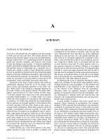
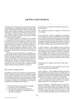
listed below. Detailed discussion may be found in Ref. 2.
Typical design of septic tank and intermittent filter are shown
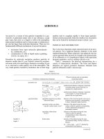
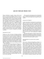
in Figure 1. Typical trench, seepage pit and mound systems
are shown in Figure 2.
Subsurface soil absorption systems
trench and bed
seepage pit
mound
fill
artificially drained systems
electro-osmosis
*
Evaporation systems
evapotranspiration and evapotranspiration—
percolation
evaporation and evapopercolation ponds
Surface water disposal
outfall in stream
outfall in lake
Aerobic System
Several types of household treatment systems are available
which utilize aerobic stabilization of organic wastes. Most
systems are designed for continuous flow.
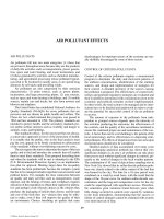
The raw wastewater enters an anaerobic tank where
solids are settled and partially digested. The liquid enters an
aerobic compartment. Air is supplied either by mechanical
aerators or by diffusers. The bacterial action thus produced
is similar to that in an activated sludge plant. The solids in
the aerated liquid are settled into a separate tank. This tank
most commonly has a sloping bottom to return the settled
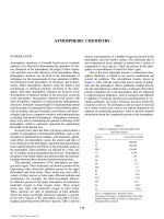
sludge into the aeration tank by gravity. System components
of such units are schematically shown in Figure 3.
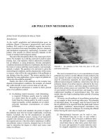
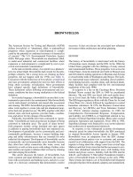
Some of the manufacturers’ variations in the aerobic system
include (1) absence of anaerobic digestion tank, (2) different
methods of aeration, (3) packed bed media, (4) trickling filter,
(5) rotating biological contactor, and (6) use of tube settlers for
increasing the sedimentation rate.
2,12
Many of these variations
are shown in Figure 4.
The effluent from an aerobic system is generally better
than that from a septic tank. Manufacturers claim BOD and
suspended solids removal of about 90%. The effluent from
aerobic systems has lower clogging effect on soil absorption
system. If the system operates properly, the effluent is suit-
able for surface drainage. The disadvantages of the aerobic
system are higher operating costs, susceptibility to shock
loading, and variation in effluent quality. The design criteria,
operational characteristics and cost data on aerobic systems
are extensively available in the literature.
2,3,13,14
Constructed Wetlands
Constructed and natural wetland rely solely on natural
process to treat wastewater and are most often used for sec-
ondary treatment. In a single-residence system, for exam-
ple, a septic tank generally provides partial treatment. The
effluent flows to the wetlands where it is distributed into
the system. Organic matter is stabilized by microorganisms
attached to the plant roots. Aquatic plants deliver oxygen,
provide shade, metabolic nutrients and surface area for
microbiological growth.
Constructed wetlands are designed either as a “discharge”
system or as an “non-discharge” system.
1
Two basic design
approaches exit for constructed wetlands. These are developed
by (1) Tennessee Valley Authority (TVA) for systems less
than 75,700 L/d, and (2) EPA for larger municipal wastewater
treatment plants. The design equations are based on hydraulic
loading, organic loading, and Darcy’s equation. The design
procedure for constructed wetland can be found in Refs. 1,
15–17. The suggested residential wetland design details are:
length ϭ 12.7 m, width ϭ 4.3m, depth ϭ 0.3 m, detention
time ϭ 3d, and hydraulic loading criteria ϭ 1.3 m
2
/L·d.
The aquatic plants are generally chosen from indig-
enous species of Typhaceae (cattail family), Cyperaceae
(sedge family), Gramineae (grass family), Scirpus validus
(softstem bulrush), or Phragmites australis (giant reed).
Care should be taken to avoid plants that “choke out” each
other, or those eaten by animals. The choice of vegetation is
dependent upon wastewater characteristics, solar radiation,
temperature, aesthetics, wildlife desired, indigenous species,
and the depth of constructed wetlands. Vegetation harvesting
may be necessary when it becomes too dense, cause obstruc-
tion to the natural flow and create anaerobic conditions.
1
SMALL ESTABLISHMENTS
Small establishments generally include motels, restau-
rants, stores theatres, clubs, camps, rest areas, institutions,
apartment houses, small factories, subdivisions, small
communities, etc. Disposal of wastewaters from these
establishments in suburban areas certainly poses serious
problems. Construction of public sewer systems may not
be economically feasible to convey the wastewaters to an
existing treatment plant. Since the flows are relatively large,
often septic tanks and subsurface absorption fields may not
provide safe disposal, causing a very serious public health
hazard or pollution of ground or surface waters.
Package treatment plants were first introduced about
thirty-five years ago to treat wastes from small establish-
ments. During this time, there has been a rapid commercial
growth in package plant industry. The package plants are
prefabricated in the factory and, in most cases, completely
assembled prior to delivery to the plant site. Most of the
plants are made of steel but many concrete plants are also
*
Electro-osmosis is a technique used to drain and stabilize slowly
permeable soils during excavation. A direct current is passed through
the soil which draws the free water in the soil pores to the cathode.
C019_002_r03.indd 1083C019_002_r03.indd 1083 11/18/2005 11:06:45 AM11/18/2005 11:06:45 AM
© 2006 by Taylor & Francis Group, LLC
1084 SMALL FLOW WASTEWATER TREATMENT TECHNOLOGY FOR DOMESTIC AND SPECIAL APPLICATIONS
FIGURE 1 Typical design of septic tank and intermittent filter. (Adapted from Ref. 2.)
Access
Manholes
Sanitary
Te e
Inlet
Vent
Liquid Level
Outlet
Graded Gravel 3/4" to 2 1/2"
Graded Gravel 1/4" to 1 1/2"
Marsh Hay or
Drainage Fabric
Top Soil Fill
Drainage
Filter Media
Peforated or Open
Joint Distributors
Perforated or Open
Joint Pipe, Tarpaper
Over Open Joints
> 8 in
> 8 in
24–36 in
> 6 in
6
"
Distribution Box
House Sewer
Septic
Ta n k
Vent Pipe
A
A
Vent Pipe
Discharge
Inspection Manhole
and Disinfection
Contact Tank
(If Required)
Profile
Plan
Section A-A
Longitudinal Section
(a) Typical design of two-compartment
septic tank
(b) Typical design of buried intermittent
filter installation
Pea
Gravel
C019_002_r03.indd 1084C019_002_r03.indd 1084 11/18/2005 11:06:45 AM11/18/2005 11:06:45 AM
© 2006 by Taylor & Francis Group, LLC
SMALL FLOW WASTEWATER TREATMENT TECHNOLOGY FOR DOMESTIC AND SPECIAL APPLICATIONS 1085
FIGURE 2 Subsurface absorption system. (Adapted from Ref. 2.)
Backfill
Barrier
Material
3/4–2-1/2 in. Rock
Water Table or
Creviced Bedrock
Perforated
Distribution
Pipe
6-12 in.
1-3 ft
1-5 ft
2-4 ft. Min.
(a) Typical trench system
4" Inspection Pipe
Reinforced Concrete Cover
Extended to Solid Earth
Effluent
Brick, Block, Ring, or
Precast Chamber
with Open Joints
6" to 12" of
3/4–2 1/2"
Clean Rock
Influent
Water Table
4' min. Unsaturated Soil
Impervious Layer
(b) Typical seepage pit system
Straw, Hay or Fabric
Fill
Topsoil
Straw, Hay or Fabric
Fill
Topsoil
Cap
Cap
Distribution Lateral
Distribution Lateral
Absorption Bed
Absorption Bed
Plowed Layer of Top Soil
Slope
Rock Strata or Impermeable Soil Layer
(c) Typical mound for a slowly permeable soil
on sloping site
3
1
Plowed Layer of Top Soil
Permeable Soil
Water Table or Creviced Bedrock
(d) Typical mound system for a permeable soil
with high groundwater or shellow creviced
bedrock
3
1
C019_002_r03.indd 1085C019_002_r03.indd 1085 11/18/2005 11:06:46 AM11/18/2005 11:06:46 AM
© 2006 by Taylor & Francis Group, LLC
1086 SMALL FLOW WASTEWATER TREATMENT TECHNOLOGY FOR DOMESTIC AND SPECIAL APPLICATIONS
available. During earlier years of package plant usage, the
plant size was usually limited to the maximum size that
could be shipped by truck. This was about 190–228 m
3
/d
(50,000 to 60,000 gallons per day (gpd)) maximum plant
size. Currently the manufacturers fabricate the plants in the
field. Thus package plants with capacities over 3800 m
3
/d
(one million gallons a day (mgd)) can be obtained.
The earlier package plants were designed as extended
aeration plants. Currently available package plants utilize
many treatment processes. Some of these processes are
listed below.
Biological
Extended aeration
Contact stabilization
Completely mixed
Step aeration
Trickling filter
Rotating biological contractor
Sequencing batch reactor (SBR)
Chemical
Chemical precipitation
Electrochemical flotation
Ultrafiltration
Detailed discussions on package plants including manu-
facturers, process alternatives, size, weight, design criteria,
and cost is extensively available in the literature.
18 – 22
These
plants have been successfully applied in the treatment of
wastewaters in the suburban areas. The range of these plants
has expanded from small establishments to large municipal
and industrial applications. Manufacturers broadly group the
models or design series into flow capacity, BOD loading,
dimensions, air supply, motor horse power, etc., which has
simplified the job of unit selection.
Influent
Influent
Blower
Effluent
Effluent
Settling
Chamber
Settling
Chamber
Sludge
Sludge
Aeration
Aeration
Trash
Tra p
Trash
Tra p
Scum
Scum
Sludge
Sludge
Diffuser
Mechanical or
Diffused Aeration
(a) Diffused aeration
(b) Mechanical aeration
FIGURE 3 System components of aerobic suspended growth biological treatment pro-
cess. (Adapted from Ref. 2.)
C019_002_r03.indd 1086C019_002_r03.indd 1086 11/18/2005 11:06:46 AM11/18/2005 11:06:46 AM
© 2006 by Taylor & Francis Group, LLC
SMALL FLOW WASTEWATER TREATMENT TECHNOLOGY FOR DOMESTIC AND SPECIAL APPLICATIONS 1087
FIGURE 4 System components of aerobic attached growth biological treatment process. (Adapted from Ref. 2.)
Motor
Effluent
Packed
Media
Influent
(a) Uptlow filter
Influent Distributor
Fixed
Media
(c) Tricking filter
Effluent to Clarifier or Septic Tank
(b) Rotating Biological contactor
Pump
Septic
Ta n k
Influent
Timer
Control
Valve
Clarifier
Motor
Effluent
Sludge
Sludge
Under Drain
C019_002_r03.indd 1087C019_002_r03.indd 1087 11/18/2005 11:06:46 AM11/18/2005 11:06:46 AM
© 2006 by Taylor & Francis Group, LLC
1088 SMALL FLOW WASTEWATER TREATMENT TECHNOLOGY FOR DOMESTIC AND SPECIAL APPLICATIONS
In recent years natural systems are also used for waste-
water treatment from small establishments and sub-divisions.
Among these are land treatment, and natural and constructed
wetland. Information on natural system may be found in
Refs. 1, 4, 15–17, 23 and 24.
POLAR REGIONS
Waste handling in polar regions is a complex problem.
Conventional wastewater collection and treatment systems
have severe limitations due to cold weather. Sewers con-
structed through snow, ice or permafrost
2
must be insulated
to transport the wastes without freezing. Waste treatment by
chemical or biological methods may not be possible due to
retarded reaction rates.
The predominant sanitary facility used in small Alaskan
villages is manual collection of human fecal waste and their
disposal to ground, snow or ice. In many cases, pit priv-
ies, vaults, bored holes, straddle trenches, box and can, and
crude chemical toilets are also used. Problems with these
systems are: inconvenient to use especially in cold climates,
unaesthetic features such as odor and unsightly conditions,
and health hazards.
25,26
Perhaps the most comprehensive analysis of waste prob-
lems in arctic areas was conducted by the Federal Housing
Administration about 50 years ago.
27,28
Subsequently, a
number of research programs were conducted by the US
Public Health Service, National Research Council, US Navy,
US Air Force, and US Army in developing suitable systems for
use in Greenland, Alaska and most recently in the Antarctic.
29
Prime requirements for a system suitable for installation in
these areas were: (1) minimum water use as year-round water
supply in these areas may be lacking, (2) non-electric opera-
tion, (3) freeze-free, (4) minimum final disposal problems,
(5) odor-free, and (6) minimum of maintenance. Systems
investigated in these research programs included: (1) incin-
erating toilets, (2) chemical toilets, and (3) chemical and bio-
logical toilets with recirculation.
Incinerating Toilets
Incinerating toilets have been designed to destroy human
body wastes. The thermal energy required may be obtained
from electricity, fuel, oil, or liquified petroleum gas (LPG).
Several designs of incinerating toilets are now commer-
cially available. Although these toilets provide complete
prevention of pollution from human wastes, they are rela-
tively inefficient in terms of fuel consumption and often
fail to provide complete burning which may result in a nox-
ious odors or excessive smoke.
28
Two incinerating toilets
Incinolet and Stornburn are manufactured for application
in Alaska.
26
Chemical and Composting Toilets
Chemical toilets require addition of chemicals into the waste
storage tank. These chemicals liquify the fecal wastes, produce
bactericidal effect and suppress fecal odors. Most commonly
used chemicals are: (1) halogens and their compounds, (2)
coal-tar distillate (phenols and cresols), (3) heavy metals
and their salts (zinc, copper and silver salts), (4) quaternary
ammonium compounds, and (5) alkaline substances such as
sodium and potassium hydroxide and lime. Various chemi-
cals are sold in the market under different trade names.
One mechanical-flush chemical toilet was developed by
Naval Engineering Laboratory, Port Huneme, California (US
Patent No. 3,460,165) for use at remote Antarctic stations.
This toilet was extensively tested by the military personnel
and found satisfactory for polar applications.
A variety of composting toilets are on the market for
application in cold region. These toilets use no water, and
eventually produce compost that can be used on home
garden. Three composting toilets named in the literature are
AlasCan, the Phoenix, and the Sun-Mar.
26,29,30
Chemical and Biological Toilets with Recirculation
A special application of waste treatment unit for polar use
is a unit where treated effluent could be recirculated as a
flush fluid. Such concepts with both chemical and biologi-
cal treatment systems were investigated. Walters developed
a recirculating chlorinator toilet which used standard toilet
fittings.
31
The heavily chlorinated effluent from the storage
tank was reused for flushing the toilet bowl. The system
was tested in Alaskan single homes and results were found
esthetically acceptable.
Another study evaluated three extended aeration plants
in which the effluent was recirculated for toilet flushing.
32
The findings of this investigation showed that the flushing
fluid turned brown during the first week and remained that
color for the entire test period of several months. However,
no odors were detected.
Both the chemical and biological treatment system with
effluent recirculation have great promise in developing toilets
for use in polar regions. These toilets have unique features
such as: no water requirement, non-electrical (with hand
pump), non-freezing, no odor, conventional toilet design,
and a minimum of maintenance.
A number of innovative wastewater collection, treat-
ment, reuse and disposal system have also been applied
for community and individual home applications in polar
region. Among these are pressurized and vacuum collection
systems, low flush, ultra-low flush, micro-flush toilets, and
mineral oil flush systems.
26,33 – 38
WATERCRAFT
Use of the waterways for pleasure boating has increased
enormously in this country. Because of a substantial increase
in the number of recreational vessels, the public has become
aware of the potential seriousness of the waterborne pollu-
tion resulting from this source. Many recreational watercraft
and commercial and government vessels discharge wastes
into the water.
34
Recreational watercraft are highly mobile,
C019_002_r03.indd 1088C019_002_r03.indd 1088 11/18/2005 11:06:46 AM11/18/2005 11:06:46 AM
© 2006 by Taylor & Francis Group, LLC
SMALL FLOW WASTEWATER TREATMENT TECHNOLOGY FOR DOMESTIC AND SPECIAL APPLICATIONS 1089
and may reach beaches, commercial fisheries, shell-fish
growing areas and may seriously contaminate the waters,
thereby rendering them dangerous for public water supplies
and water contact sports. Contamination may also seriously
affect the commercial fisheries and the shellfish industry.
The discharge in territorial waters of the United States
is regulated by the Clean Water Act.
40
This Act also speci-
fies allowable types of marine sanitation devices (MSD), and
mandates, that the US Coast Guard test the various types of
MSD and certify them for use aboard water craft. These tests
are found in 33CFR 159, page 492, 500 and 501.
41,42
Type
I MSD utilize macerator and disinfection. Both commercial
disinfectants and onsite electrochemical devices are included.
Type II MSD include biological treatment or fiber filtration
(microscreening). Type III MSD consists of storage tank.
Sewage equipment for use aboard watercraft is already
available in the form of (1) maceration-disinfection devices,
(2) holding tanks and recirculating toilets, (3) incinerator
devices, and (4) chemical and biological treatment facili-
ties. A brief discussion of these systems is given below. For
details on manufacturers, cost and unit variations, readers
are referred to several sources in the literature.
43 – 49
Maceration-Disinfection Devices
Maceration-disinfection devices utilize a mechanical macera-
tor to grind the human fecal wastes, mix a disinfecting chemi-
cal (usually hypochlorite) and retain the disinfected sewage
mixture for a brief period before discharging it into the water.
A number of companies manufacture such units for installation
aboard virtually every type of watercraft. Such units are small,
lightweight, and relatively easy to install. However, their per-
formance in terms of BOD and suspended solids reduction,
and degree of disinfection achieved may be questionable.
Holding Tanks and Recirculating Toilet
A holding tank is a closed container for retaining sewage
onboard a watercraft until it can be properly emptied, usu-
ally into an onshore sewage receiving facility. Holding tanks
include chemical toilets, recirculating flush toilets, classic
holding tanks, and any variation which simply retains the
sewage for later disposal at an appropriate site.
One potentially useful variation of the holding tank is
the recirculating flush toilet. This device requires a small
amount of precharge of chemically treated water in the reten-
tion tank integrated into the toilet design. Waste deposited in
this toilet accumulates in the retention tank. For subsequent
flushing, an internal separation mechanism recovers a frac-
tion of this precharge/waste mixture for continued reuse as
flushing fluid. The tank retains sewage from 80 to 100 toilet
usages before it must be emptied. It uses minimum space
and requires no water for flushing.
Although holding tanks completely prevent the discharge
of sewage from watercraft, they require extensive shore sup-
port facilities for emptying and cleaning. Low flush and
vacuum flush toilets are desirable because they minimize
storage and treatment requirement.
34
Incinerator Devices
As described earlier, several types of incinerating toilets have
been developed to reduce human waste to a small amount of
ash. The most common problems encountered with incinera-
tor devices with watercraft include the difficulty of supplying
electrical power as most small craft do not have the generat-
ing equipment required. If gas or oil burner type incinerators
are used, space is also required. Such burners also provide
fire hazards if improperly designed. Regardless of the type
of fuel used, however, burning of human wastes may result
in emission of odor from the venting stack.
Chemical and Biological Treatment Plants
Wastewater treatment plants similar to those frequently used
for land-base sewage treatment have been adopted for vessel
use. The mot successful of the biological treatment systems
are the extended aeration activated sludge process.
48
Attempts
have been made also to adapt thermally heated aeration sys-
tems for increased biological activity. Trickling filter-type
biological treatment systems with forced air aeration have
also been adopted to shipboard applications.
18
These sys-
tems, which provide treatment to all waste streams gener-
ated aboard the watercraft, are relatively large and heavy,
and easily upset due to change in salinity of flush water.
Among the chemical systems, an electrochemical floata-
tion plant for shipboard waste treatment was designed and
built.
49,50
This system utilized chlorine gas for disinfection,
and partial oxidation and flotation of organic matter. Another
chemical process oriented system utilized a comprehensive
approach to the management of wastewater on board ship
and is concerned not only with an improved treatment but
also with an innovation and improved collection system.
The system employs two main elements: (1) a recirculating
chemical toilet, and (2) an evaporation system for solid/liquid
separation.
31,51 – 53
Condensed liquid is discharged overboard
after chlorination. Concentrated sludge is stored for subse-
quent disposal to shore facility or into unrestricted waters.
COMMERCIAL AIRCRAFT
Until about 1940, waste management problems aboard air-
craft were considered minor; human wastes were simply dis-
charged overboard. In January of 1943, the US Public Health
Service published the “Sanitation Manual for Land and Air
Conveyance Operating in Interstate Traffic,” which formu-
lated policy regarding “Discharge of Wastes from Conveyance
En Route.”
54
Following this publication, the International
Sanitary Convention for Aerial Navigation issued a publica-
tion in February, 1945, forbidding aircraft to throw or let fall
matter capable of producing an outbreak of infectious dis-
eases.
55
Federal laws and regulations now prohibit air-planes
indiscriminately discharging untreated human wastes.
56
Early waste management practices for aircraft included
carry-out pail methods of waste collection within aircraft
and hand-carrying them to the ground servicing facilities.
C019_002_r03.indd 1089C019_002_r03.indd 1089 11/18/2005 11:06:46 AM11/18/2005 11:06:46 AM
© 2006 by Taylor & Francis Group, LLC
1090 SMALL FLOW WASTEWATER TREATMENT TECHNOLOGY FOR DOMESTIC AND SPECIAL APPLICATIONS
Subsequently, this system was replaced by built-in retention
tanks. These retention tanks utilized wash and galley water
for toilet flushing purposes. The system posed several opera-
tional problems, including the fact that the flushing water
taxed the capacity of the retention tanks on longer flights,
and was later replaced by recirculating chemical toilets.
Recirculating chemical toilets currently being used aboard
commercial aircraft have highly improved features to fulfill
the requirements of the modern planes. Reinforced fiber-
glass retention tanks for lightness, teflon coated toilet bowls
for cleanliness, timer assemblies to control the flush cycle,
improved reversible-motor-operated pumps, and a number of
filter and filter-cleaning devices have all been developed to
provide trouble-free operation and an aesthetic facility.
The recirculating chemical toilets provide efficient oper-
ation but, depending on the capacity of the water tank, the
system requires frequent ground servicing. Furthermore, the
amount of space and weight available for waste storage in
aircraft is quite limited. Therefore, a system to concentrate
the wastes during the flight is considered highly desirable.
To achieve this, several waste-volume-reduction techniques
have been investigated for use aboard commercial aircraft.
These include:
1) Evaporation of the liquid to yield dry or highly
concentrated solids to reduce the waste-storage
space in the aircraft and eliminate the frequent
ground servicing need.
2) Incineration devices which utilize electrical
and fuel energy for waste incineration. Several
improved incineration systems for aircraft appli-
cation have been built and evaluated.
57 – 59
3) Evapo-combustion system to burn the macerated
waste into a combustion chamber of the jet en-
gine. Vacuum toilets have also been successively
installed on large commercial aircraft. These toi-
lets reduce the waste accumulation.
34, 60 – 64.
RAILROAD TRAINS
Historically, wastes from railroad trains have been discharged
into the environment without benefit of any treatment. This
primitive practice poses a threat to the public health. Although
passenger traffic on trains in the US has declined in recent
years, large numbers of persons, including railroad employees
still use toilet facilities on trains. According to Food and Drug
Administration (FDA), about 23 million pounds of human
excrement or 16 million gallons of wastewater are discharged
annually from locomotives and cabooses, and about 9.5 mil-
lion gallons of “untreated human wastes” were discharged in
1968 from intercity and commuter passenger train cars.
56
A
history of some of waste disposal practices of Amtrak was
presented in a hearing before Congress in 1988.
65
Federal laws and regulations now prohibit buses
(42 CFR 72.156) from discharging untreated human
waste.
56,57
As a result, the passenger buses are equipped with
suitable types of chemical or recirculating toilets.
Currently, several types of waste treatment and disposal
systems are being marketed which are designed and built for
railroad trains. These include incinerating toilets, retention
tanks, and recirculating toilets.
Incinerating toilets built for railroad cars operate on
natural gas, propane, diesel fuel, or electricity. These toilets
operate without the use of water or chemicals and require no
holding tanks or plumbing fixtures.
Recirculating toilets of various types are also available
for railroad use. One system built for locomotives, cabooses
and crew cars uses a vacuum system. In this system air,
rather than water, is used to carry waste from the toilets to a
centrally located tank.
56,61
This system enables locating the
holding tank elsewhere in the railroad car and two or more
toilets can be connected to this tank.
PICKUP CAMPERS, TRAVEL-TRAILERS, TENT
CAMPING
Various types of portable recirculating toilets are currently
manufactured. These units have suitcase-style handles
molded into their cases for easy carrying; can be used in
tents or in camper.
66
A small family can get a few day’s use
before the facility must be emptied and recharged.
A unique system for reducing the volume of wastes
from recirculating toilets was developed. In this system, the
fecal wastes were liquefied by adding chemicals. The liquid
mixture is pumped to a sanitizer which is a short, stainless
steel tank connected to the exhaust pipe of the vehicle. The
sanitizer operates at about 500°F. At this operating tempera-
ture, the waste is concentrated and the microorganisms are
destroyed.
66
The operating temperature of the sanitizer is
reached at a vehicle speed of about 35 mph.
ENVIRONMENTAL CONTROL AND LIFE SUPPORT
SYSTEMS (ECLSS) FOR SPACE STATION
NASA has sponsored programs to develop efficient, compact
equipment to handle the various aspect of environmental life
support for spacecraft and for the planned space station. The
tasks include CO
2
removal, O
2
regeneration, temperature and
humidity control, the purification of water recovered from
the dehumidifier condensate, hygiene uses, and in the future,
from urine. Also the removal of trace contaminants from the
air, the maintenance of the air composition and pressure, and
the storage of solid wastes pending their return to earth are
included. A wide variety of techniques have been evaluated
depending upon their prospects for meeting the desired per-
formance specifications.
67 – 73
Table 1 provides a list of ECLSS
technologies used or evaluated.
The space systems have grown in complexity and compre-
hensiveness as both the duration of the missions and the size
of the crew have increased. With the possibility of long dura-
tion space missions to other planets, and also the establishment
of bases on the moon, NASA is in the early stages of testing
technologies for solid waste treatment and recycling, and the
C019_002_r03.indd 1090C019_002_r03.indd 1090 11/18/2005 11:06:46 AM11/18/2005 11:06:46 AM
© 2006 by Taylor & Francis Group, LLC
SMALL FLOW WASTEWATER TREATMENT TECHNOLOGY FOR DOMESTIC AND SPECIAL APPLICATIONS 1091
intensive agricultural technique necessary to grow and process
food in very confined spaces under low or zero gravity.
Some of the technologies developed for the space
program have possible application on earth. Many of the
applications will only be relevant to submarines and hyper-
baric chambers. In some cases there may be more widespread
uses, such as the recovery and reuse of dehumidification and
hygiene water in arid areas or in very cold climates, remov-
ing CO
2
and regenerating O
2
, and controlling temperature
and humidity in deep mines or while drilling long tunnels.
Certain technologies may be applicable to the treatment of
industrial emissions and/or effluents. It is likely that the
basic technological knowledge will be applied to terrestrial
problems, rather than the actual hardware developed for the
space program.
74 – 77
Possible terrestrial application of space
craft environmental systems are presented in Table 2.
TABLE 1
ECLSS technologies used or evaluated
ECLSS subsystem category Used/Evaluated Technology
Atmosphere revitalisation Used LiOH
Used Molecular sieve
Used Sabatier reactor
Used Static feed water electrolysis
Evaluated Solid amine fixed bed
Evaluated Liquid sorbent closed loop
Evaluated Bosch system
Evaluated Algal bioreactor
Evaluated Growing green plants
Trace contaminant removal Used Activated charcoal
Used Catalytic oxidiser
Used Particulate filters
Water recovery and management Used Vapor compression distillation
Used Chlorine
Used Sodium hypochlorite injection
Used Iodine injection
Used Heat sterilisation
Used Fuel cell byproduct water
Evaluated Unibed filter
Evaluated TIMES membrane filter
Evaluated Reverse osmosis
Evaluated Electrodialysis
Evaluated Electrooxidation
Evaluated Supercritical water oxidation
Evaluated Electrodeionisation
Evaluated Air evaporation
Evaluated Vapor phase catalytic
ammonia removal
Evaluated Immobilised cell or enzyme bioreactors
Evaluated Plant transpiration and water recovery
Temperature and humidity control Used Condensing heat exchangers
Used Water cooled suits
Atmosphere control and supply Used Compressed gas storage
Used Cryogenic gas storage
Waste management Used Urine stored in bags
Used Feces stored in bags
Used Urine vented
Used Feces stored in bags and vacuum dried
Used Urine stored in tank and vented
Used Feces stored in bags and compacted
C019_002_r03.indd 1091C019_002_r03.indd 1091 11/18/2005 11:06:47 AM11/18/2005 11:06:47 AM
© 2006 by Taylor & Francis Group, LLC
1092 SMALL FLOW WASTEWATER TREATMENT TECHNOLOGY FOR DOMESTIC AND SPECIAL APPLICATIONS
A joint NASA and NSF life support system utilizing some
of the water recovery, waste treatment, plant growth, and energy
efficiency technologies is to be installed at the US research sta-
tion at the South Pole. This will provide a real world opportu-
nity to use the planned technologies on a realistic scale.
78
REFERENCES
1. Sauter, G. and K. Leonard, Natural Home Remedy, Water Environment
& Technology, Water Environment Federation, 7, No. 8, pp. 48–52
(August 1995).
2. US Environmental Protection Agency, Design manual, Onsite waste-
water treatment and disposal systems, Office of water Program Opera-
tions, Municipal Environmental Research Laboratory, Cincinnati,
Ohio, EPA 625/1-800-012, October 1980.
3. US Environmental Protection Agency, Handbook of Septage Treat-
ment and Disposal, USEPA 625/6-84-009, Center for Environmental
Research Information, Cincinnati, OH, October 1984.
4. Qasim, S.R., Wastewater Treatment Plants: Planning, Design and
Operation, Technomic Publishing Co., Lancaster, PA (1994).
5. Manual of septic-tank practice, USPHA, Publication No. 526, US
Department of the Interior, Washington D.C. (1967).
6. Coulter, J.B., The septic tank system in suburbia, Pub. Health Rept., 73,
488 (1958).
7. Winneberger, J.H., et al. , Biological aspects of failure of septic tank
percolation systems, Final report, Sanitary Engineering Research Labo-
ratory, University of California, Berkeley (August 1969).
8. Laak, Rein., Wastewater Engineering Design for Unsewered Areas,
Second edition. Technomic Publishing Co. , Lancaster. PA. (1986).
9. Andreadakis, A.D., Organic matter and nitrogen removal by an on-site
sewage treatment and disposal system, Water Research (G.B.), 21, 559
(1987).
10. Scalf, M.R. et al., Environmental effects of septic tank systems, US Envi-
ronmental Protection Agency, Ada, Oklahoma, EPA-600/3-77-096, 1977.
11. Sharp, W.E. et al., Restoration of Failing On-site Wastewater Disposal
Systems Using Water Conservation, Journal Water Pollution Control
Federation, 56, No. 7, pp. 858, (July 1985).
12. Reid and Leroy C. Jr., Design of wastewater disposal systems for indi-
vidual dwellings, Journal Water Pollution Control Federation, 43,
No. 10, pp. 2004–2010 (October 1971).
13. Report on Individual household aerobic sewage treatment systems,
National Research Council–National Academy of Science, Publication
No. 586 (February 1958).
14. Thomas, H.A. Jr. et al. , Technology and economics of household
sewage disposal systems, Journal Water Pollution Control Federation,
32, No. 2, p. 113 (February 1960).
15. U.S. Environmental Protection Agency, Design Manual on Constructed
Wetland and Aquatic Plant System for Municipal Wastewater Treatment
Plants, Office of Research and Development, Center for Environmental
Research Information, Cincinnati, Ohio, (September 1988).
16. U.S. Environmental Protection Agency, Subsurface Flow Constructed
Wetland for Wastewater Treatment – A Technology Assessment, Office of
Water, EPA 832-R-93-00, (July 1993).
17. U.S. Environmental Protection Agency, Subsurface Flow Constructed
Wetlands, Proceedings of the Subsurface flow Constructed Wetlands
Conference, August 16 and 17, 1993, University of Texas at EL Paso,
(1993).
18. Qasim, S.R., N.L. Drobny, and B.W. Valentine, Process alternatives
available in packalaged wastewater treatment plants, Water and Sewage
Works, 177, Reference Number, pp. R-99 (November 1970).
19. Mahoney, J.A., Summary of commercial wastewater treatment plants,
report No. AD 860 067, Air Force Systems Command, Kirtland Air
Force Base, New Mexico, (September 1969).
20. Seymour, G.G., Operation and performance of package treatment
plants, Journal Water Pollution Control Federation, 44, No. 2, pp. 274
(February 1972).
21. Defne, R.R., G.E. Elbert, and M.D. Rockwell, Contact stabilization in
small package plants, Journal Water Pollution Control Federation, 44,
No. 2, p. 255 (February 1972).
22. Sancier, J.W., The application or package wastewater treatment plants to
suburban areas, Water and Wastes Engineering, p. 33. (December 1969).
23. Water Pollution Control Federation, Natural Systems for Wastewater
Treatment, Manual of Practice F9–16, Water Pollution Control Federa-
tion, Washington D.C. (1990).
24. Dinger, R., Natural Systems for Water Pollution Control, Van Nostrand
Reinhold Co. New York, (1982).
25. Mellor, M., Utility on Permanent Snowfields, Monograph III-A2d,
U.S. Army Corps of Engineers, Cold Regions Research Laboratory,
Hanover, NH (1969).
26. An Alaskan Challenge: Nature Village Sanitation, US Department of
Housing and Human Services, Y3.T 22/2:2AL 1S, (1994).
27. Alter, A.J., Arctic sanitary engineering, Federal Housing Administra-
tion, Washington, DC (1950).
28. Clark and Groff Engineers, Sanitary waste disposal for navy camps in
polar regions, final report to Naval Civil Engineering Laboratory on
Contract NBy-32205 (1962).
29. A New Device for Cold Region Sanitation Disposal—the Alas-Can,
The Northern Engineer, 22, No. 1, (Spring 1990).
30. Product Literature, Lehman Hardware and Appliances, Inc., Kidron,
Ohio (1995).
31. Walters and Charles F., Promise disposal system, Water and Sewage
Works (August 1962).
32. Walters, Charles F. and J.A. Anderegg, Water conservation through
reuse of flushing liquid in an aerobic sewage treatment process, paper
presented at 11th Alaska Science Conference (August 20, 1960).
33. Kouric, R., Toilets: Low Flush/No Flush, Garbage: The Practical Jour-
nal for the Environment, 2, No. 1, pp. 16–24, (January 1990).
34. Water-wise Toilets, Technology Review, 97, (1994).
TABLE 2
Possible terrestrial applications of spacecraft environmental systems
ECLS systems Possible earthbound uses
Water reclamation Submarines, arid area operations, supply of filtered and sterile water for medical, experimental
uses. Cleaning industrial effluent.
Oxygen generation Submarines, medical use in oxygen enriched atmosphere, hyperbaric chambers, under water
habitats and deep undergroundwork locations.
CO
2
removal Submarines, rescue and scuba equipment, under water habitats, hyperbaric chambers. Cleaning
industrial emmissions. Revitalising atmosphere in deep underground work locations.
Trace contaminant removal Submarines, under water habitats, hyperbaric chambers.
Temperature, humidity control Passive systems developed for the control of the space station temperature gain and loss from and
to space itself may have some terrestrial applications. Active systems used in controlling
temperature in locations where there are localised sources of heat may be useful for cooling
dense electronics, in satellites, possibly in aircraft, and perhaps in advanced super computers.
C019_002_r03.indd 1092C019_002_r03.indd 1092 11/18/2005 11:06:47 AM11/18/2005 11:06:47 AM
© 2006 by Taylor & Francis Group, LLC
SMALL FLOW WASTEWATER TREATMENT TECHNOLOGY FOR DOMESTIC AND SPECIAL APPLICATIONS 1093
35. Pollen, M.R. and D.W. Smith, Water Conservation in Borrow Alaska,
Proceedings of the Third Symposium on Utilities Delivery in Cold
Regions, University of Alberta, Edmonton, Alberta, Canada (1982).
36. Viraraghavan, T. and G. Mathavan, Effect of Low Temperature on Physi-
cochemical Processes in Water Quality Control, Journal of Cold Regions
Engineering, American Society of Civil Engineers, 2, No. 3, (1988).
37. U.S. Environmental Protection Agency, Water Related Utilities for
Small Communities in Alaska, EPA-600/3-76-104, Environmental
Research Laboratory, Office of Research and Development. Corrallis,
Oregon, (1976).
38. Bowen, P.T. and J.C. Lan, Wastewater Treatment of the South Pole,
Water Environment and Technology, 5, No. 3, (March 1993).
39. Federal Water Pollution Control Administration, Wastes from water-
craft, US Senate, 90th Congress 1st Session, Document No. 48, US
Government Printing Office, Washington, DC (August 7, 1967).
40. The Clean Water Act Amendments of 1981, PL 97–117, Title III, Sec.
311.(b)(1).
41. 33 CFR, Part 159, Marine Sanitation Devices, (1994).
42. Wachinski, A.M. and M. Knofczynski, Managing Shipboard Wastes,
Water Environment and Technology, Water Environment Federation, 4,
pp. 58–62 (August 1992).
43. Hertzbery, R.H., Waste disposal from watercraft, Journal Water Pollu-
tion Control Federation, 40, No. 12, p. 2055 (December 1968).
44. Oertle, Lee, Plan a head, monomatic self-contained recirculating head,
Popular Mechanics, p. 140 (December 1968).
45. Manning, A.P., Headspace and horse sense on chlorinator, Motor Boat-
ing, pp. 42–47 (March 1968).
46. Dugan, P.R. and F.M. Pfister, Evaluation of marine toilet chlorinator
units, New York State Department of Health, Project No. GL-WP-1
(July 1962).
47. Yacht Safety Bureau, Inc., Requirements of marine sewage incinerating
devices (February 1968).
48. Stewart, M.J. and H.F. Ludwig, Shipboard extended-aeration waste-
water treatment plant design, Naval Engineering Journal, 109, pp. 985
(December 1963).
49. Singerman, H.H. and E.T. Kinney, The Navy’s technological prog-
ress in water pollution abatement, Naval Engineers Journal, pp. 795
(October 1968).
50. Bockris, J.O. and Z. Nagy, Electrochemistry for Ecologist, Plenum
Press, New York (1974).
51. Qasim, S.R. and N.L. Drobny, Development of a waste treatment
system for naval vessels phase I-laboratory studies, research report,
Battelle Memorial Institute, Columbus Laboratories (October 1970).
52. Droby, N.L., S.R. Qasim, and A. Cornish, Waste management systems
for naval vessels, proceedings of the 17th Annual Meeting and Equip-
ment Exposition, Institute of Environmental Sciences, Los Angeles,
California (April 1971).
53. Joungs and Jim, et al. , Accessory Guide, Trailer Boats, pp. 70–78,
(April 1995).
54. Sanitation manual for land and air conveyance operation in interstate
traffic, Public Health Service report, 58, No. 5, pp. 157–193 (January
29, 1943).
55. Handbook on sanitation of airlines, US Department of Health, Educa-
tion and Welfare, Public Health Service Publication No. 308, Vol. 31,
Washington, DC (1953).
56. Environmental pollution: Discharge of raw human wastes from rail-
road trains, 32nd report by the Committee on Government Operations,
Washington, DC (October 8, 1970).
57. U.S. Congress, Discharge of Waste on Air and Highway Conveyances,
Public Law, 21 CFR, 40 CFR 56524, February 1975, and as amended
48CFR 11432, March 18, 1983.
58. Fredric, E.W. and B. Mangus, Waterless toilet, US Patent 3, 110,037
(C14-131) (November 1963).
59. Krukeberg, C.W. and R.J. Jauch, Assignors to Tokheium corporation,
Indiana, Incinerating Toilet, US Patent 2,995,097 (C1 110-9) (August
1961).
60. Duncan, Leon, L., Assignor to William J. King, Palos Park, III., Total
disposal unit and method, US Patent, 3, 319,588 (C1 110-9) (May
1967).
61. Watkins, A.M., Sanivac-Revolutionary vacuum toilets, Popular Sci-
ence, p. 86 (July 1970).
62. Kourik, R., Toilets: The Low-flush/No Flush Story, Garbage, p. 16,
(January/February 1990).
63. Research Products/Blankenship, Incinolet: That Electric Toilet,
Research Products/Blankenship (August 1994).
64. Alternative Toilets, National Small Flows Clearing House, US Envi-
ronmental Protection Agency, West Virginia University, Morgantown,
W.Va. (March 1994).
65. Committee on Government Operations, Government Activities and
Transportation Subcommittee, Dumping of Human Waste from Amtrak
Trains, Hearing Before a Subcommittee of the Committee on Govern-
ment Operation, House of Representatives, 100th Conferee, Second
Session, Washington, D.C., September 27, 1988.
66. For the travelling family: Take along comfort station, Popular Science,
p. 99 (August 1970).
67. Hightower, T.M., Recycling and Source Reduction for Long Duration
space Habitation, Proceedings of the 22nd International Conference
on Environmental Systems, Seattle, WA, July 13–16, 1992. Society of
Automotive Engineers, Warrendale, PA (1992).
68. Wieland, P.O. Designing for Human Presence in Space: An Introduc-
tion to Environmental Control and Life Support Systems. George C.
Marshall Space Flight Center, NASA RP-1324 (1994).
69. Ramananathan, R., J.E. Straub, and J.R. Shultz. Water Quality Program
Elements for Space Station Freedom, Proceedings of the 21st Inter-
national Conference on Environmental Systems, San Francisco, CA,
July 15–18, 1991. Society of Automotive Engineers, Warrendale, PA,
pp. 1–21 (1991).
70. McElroy, J.F., T.M. Molter, and R.J. Roy, SPE Water Electrolyzers
for Closed Environment Life Support, Proceedings of the 21st Inter-
national Conference on Environmental Systems, San Francisco, CA,
July 15–18, 1991. Society of Automotive Engineers, Warrendale, PA,
pp. 261–270. (1991).
71. Howard, S.G. and J.H. Miernik, An Analysis of Urine Pretreatment
Methods for Use on Space Station Freedom, Proceedings of the 21st
International Conference on Environmental Systems, San Francisco,
CA, July 15–18, 1991. Society of Automotive Engineers, Warrendale,
PA, pp. 157–166 (1991).
72. Herrman, C.C. and T. Wydeven, Physical/Chemical Closed-loop Water
Recycling for Long Duration Missions, Proceedings of the 21st Inter-
society Conference on Environmental Systems, Williamsburg, VA,
July 9–12, 1990. Society of Automotive Engineers, Warrendale, PA,
pp. 233–245(1990).
73. Miernik, J.H., B.H. Shah, and C.F. McGriff. Waste Water Processing
Technology for space Station Freedom: Comparative Test Data Analy-
sis, Proceedings of the 21st International Conference on Environmental
Systems, San Francisco, CA, July 15–18, 1991. Society of Automotive
Engineers, Warrendale, PA, pp. 229–239 (1991).
74. Rossier, R.N., Nuclear Powered Submarines and the Space Sta-
tion: A Comparison of ECLSS Requirement, Proceedings of the 16th
Intersociety Conference on Environmental Systems, San Diego, CA,
July 14–16, 1986. Society of Automotive Engineers, Warrendale, PA,
pp. 321–329 (1986).
75. Straight, C.L. et al. , The CELSS Antarctic Analog Project: A Valida-
tion of ECLSS Methodologies at the South Pole Station, In Proceedings
of the 23rd Intersociety Conference on Environmental Systems, Colo-
rado Springs, CO, July 12–15, 1993. Society of Automotive Engineers,
Warrendale, PA, pp. 1–11 (1991).
76. Sribnik, F., R.C. Augusti, and E.G. Glastris, Life Support System for a
Physically Isolated Underground Habitat. In Proceedings of the 20th
Intersociety Conference on Environmental Systems, Williamsburg, VA,
July 9–12, 1990. Society of Automotive Engineers, Warrendale, PA,
pp. 1–11 (1990).
77. Dempster, W.F., Biosphere II, Engineering of Manned Closed Ecologi-
cal Systems. Journal of Aerospace Engineering, 4, No. 1, Jan 1991,
pp. 23–30.
78. Flynn, M.T., C. Straight, and D. Bubenheim, Development of an
Advanced Life Support Testbed at the Amundsen-Scott South Pole
Station. Preprint.
SYED R. QASIM
The University of Texas at Arlington
C019_002_r03.indd 1093C019_002_r03.indd 1093 11/18/2005 11:06:47 AM11/18/2005 11:06:47 AM
© 2006 by Taylor & Francis Group, LLC