ENCYCLOPEDIA OF ENVIRONMENTAL SCIENCE AND ENGINEERING - VAPOR AND GASEOUS POLLUTANT FUNDAMENTALS pps
Bạn đang xem bản rút gọn của tài liệu. Xem và tải ngay bản đầy đủ của tài liệu tại đây (1.35 MB, 31 trang )
1211
V
VAPOR AND GASEOUS POLLUTANT FUNDAMENTALS
The toxic gases produced during combustion and other
chemical processes may be removed by destructive dis-
posal, dispersive dilution or as recoverable side products.
The removal path chosen is at the present time motivated
primarily by economics, but public pressure and aware-
ness of environmental problems also influence the choice.
This section will concern itself with destructive dis-
posal and/or various recovery processes, the subject of dis-
persion being ably handled in the sections on Air Pollution
Meteorology and Urban Air Pollution Modeling. The main
emphasis will be on principles of gaseous reaction and
removal with the description of equipment for air pollu-
tion abatement covered by pollutant. Problems specifi-
cally concerned with the automobile can be found under
Mobile Source Pollution. Although the control principles
to be described below are general, it is usually necessary
to design equipment for each installation because of varia-
tions in physical and chemical properties of effluents;
also, in general, the cost of adding pollution devices to an
existing unit (retrofit) will be higher than if they were placed
in the original design, because of construction difficulty and
downtime.
Although the majority of effluent material from com-
bustion occurs in the gaseous state, it is important to char-
acterize the total effluent stream for control purposes. For
example, the effluent may be condensible at operating
temperature (a vapour) or noncondensible (a gas), but it
usually is a mixture of the two. Particulate matter (solids)
and mists (liquids) are often suspended in the gaseous
stream; if the particles do not separate upon settling they
are called aerosols. The considerations in this section deal
with gas or vapor removal only and not with liquid or solid
particle removal.
SULFUR DIOXIDE, SO
2
, AND TRIOXIDE, SO
3
Sulfur dioxide is generated during combustion of any sulfur-
containing fuel and is emitted by industrial processes that use
sulfuric acid or consume sulfur-containing raw material. The
major industrial sources of SO
2
are sulfuric acid plants, smelt-
ing of metallic ores, paper mills, and refining of oil. Fuel com-
bustion accounts for roughly 75% of the total SO
2
emitted.
Associated with utility growth is the continued long term
increase in utility coal consumption from some 650 million
tons/year in 1975 to between 1400 and 1800 million tons/year
in 1990. Also the utility industry is increasingly converting
to coal. Under the current performance standards for power
plants, national SO
2
emissions are projected to increase approx-
imately 15 to 16% between 1975 and 1990 (Anon. 1978). The
SO
2
emitted from power plants is usually at low concentration
(0.5% by volume). However, a 900 MW unit will emit over
13,000 pounds of SO
2
per hour for a 1% sulfur coal. The SO
2
emitted from industrial processes is at higher concentrations
and lower flow rates. The emitted SO
2
combines readily with
mists and aerosols, thus compounding the removal problem.
Information concerning emissions standards is essential
to pollution control engineering design. The current US fed-
eral SO
2
emissions limits for a stack are 1.2 lb/10
6
BTU for
new oil and gas fired plants. Also, uncontrolled SO
2
emis-
sions from new plants firing solid, liquid, and gaseous fuels
are required to be reduced by 85%. The percent reduction
requirement does not apply if SO
2
emissions into the atmo-
sphere are less than 0.2 lb/10
6
BTU.
Flue gas desulfurization (FGD) methods are catego-
rized as nonregenerable and regenerable. Nonregenerable
processes produce a sludge that consists of fly ash, water,
calcium sulfate and calcium sulfite. In regenerable pro-
cesses, SO
2
is recovered and converted into marketable
by-products such as elemental sulfur, sulfuric acid or con-
centrated SO
2
. The sorbent is regenerated and recycled.
The US Environmental Protection Agency believes the
following types of FGD systems are capable of achieving
the emissions limit standards: lime, limestone, Wellman-
Lord, magnesium oxide and double alkali. Due to the pro-
cess economics, utility industry prefer the lime/limestone
systems. Limestone processes constitute about 58% of the
current calcium-based capacity in service and under con-
struction, and 69% of that planned, which amounts to 63% of
C022_001_r03.indd 1211 11/18/2005 2:32:34 PM
© 2006 by Taylor & Francis Group, LLC
1212 VAPOR AND GASEOUS POLLUTANT FUNDAMENTALS
the total (De Vitt et al., 1980). The following reactions take
place in the limestone systems:
CaCO(s)CaCO(aq)
2CaCO(aq)2HCaCHCOCa
SO(g)SO(aq
33
33
2
22
�
�
�
))
SO(aq)HOHSOHSOH
HSOO(aq)SOH
CaSO
22233
3
1
2
24
2
2
→
→
�
44
2
44
CaSO(aq)CaSO(s)
�→↓
Or
Ca2ClCaCl(aq)CaCl(s)
2HSOHSO
HClHCl
Ca(H
2
22
4
2
24
�
�
�
→↓
CCO)2HCa2HCO
HCOCOHO
32
2
23
2322
�
�
The dissolution rate of limestone depends on the pH
values. The pH values encountered in practical operations
of limestone systems is in most cases between 5.5 and 6.5.
If the limestone systems operate at too low pH, SO
2
removal
efficiency will decrease. At too high pH, the scale formation
will be promoted. Other factors affecting the performance of
limestone systems include solids content, liquid-gas ratio,
and corrosion. A discussion can be found elsewhere (De Vitt
et al., 1980).
In selecting the FGD processes, the following should be
considered:
1) process type: wet or dry, regenerable or non-
regenerable.
2) chemical reagent used.
3) end-product produced: saleable product or dis-
posable waste.
The reagent, end product, principle of operation, and SO
2
removal efficiency of major FGD processes are shown in
Table 1 (Princiotta, 1978). For details of SO
2
removal refer
to the Stack gas cleaning sections.
Sulfur dioxide reacts slowly with a large excess of oxygen
in the presence of sunlight to form trioxide. Gerhard (1956)
showed that the process occurs with O
2
at a rate of 0.1–0.2%
per hour and Cadle (1956) with ozone, O
3
, at 0.1% per day.
Niepenburg (1966) illustrates the effects of oxygen in the
waste gas during combustion of oil.
The conversion of SO
2
to SO
3
is believed to be possible
at realistic rates because of the presence, on diverse surfaces,
of Fe
2
O
3
which acts as a catalyst. The SO
3
has a short lifetime
since it readily combines with water vapor in the atmosphere
to form sulfuric acid.
Oxides of Nitrogen, NO
x
NO
x
is produced in all combustions which take place using air
as an oxygen supply and in those chemical industries employ-
ing nitric acid. More than 55% of the total NO
x
emissions of
20 million tons originate from stationary sources as shown in
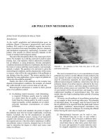
Figure 1, and 93% of all stationary source NO
x
emissions are
from combustion of fossil fuels for utilities. Direct industry-
related emissions account for only 5% of the stationary source
total. Approximately 30% of all stationary source NO
x
is emit-
ted by coal-fired utility boilers. Uncontrolled NO
x
emissions
from coal-fired sources have been measured in the range 0.53
to 2.04 lb/10
6
BTU at full load (Ziegler and Meyer, 1979). The
NO
x
formed in combustion is from fixation of atmospheric
nitrogen and/or fuel nitrogen. Ermenc (1956) found that at
high temperature nitrogen and oxygen combine to form both
NO and NO
2
. The yield of NO increases from 0.26% at 2800F
to 1.75% at 3800F. If the temperature is reduced slowly the
reverse reaction will take place, but if the products are quenched
by rapid heat exchange, the reverse reaction rate becomes small
and the oxides remain in the exhaust stream. The oxide NO can
usually be oxidized to form NO
2
according to:
2NOO2NO .2→2
Because this is a tri-molecular gas phase reaction, the con-
centration of NO and NO
2
tremendously affects the rate at
which the oxidation takes place. At low concentration, for
example 1–5 ppm in air, the reaction is so slow that it would
be negligible except for the photochemical reactions which
take place in the presence of sunlight. The dioxide also reacts
with oxygen to form ozone. The existence of nitrogen trioxide
at low concentration in polluted atmospheres is postulated
(Hanst, 1971) to form by the reaction with ozone.
NOONOO2332�
and remain in equilibrium with N
2
O
5
NONONO.2523�
The NO
3
formation reaction only takes place after NO is sub-
stantially depleted in the atmosphere and O
3
begins to appear.
Without more stringent control of new sources, the NO
x
emissions by 1995 are projected to be 66% higher than than
in 1985. Even with application of the best control method to
all new sources there is still a projected 24% increase over 10
year emissions (McCutchen, 1977). The typical NO
x
emis-
sion from nitric acid plants is 1000–3000 ppm. The federal
standard for new nitric acid plants is 3 lb NO
x
/ton 100%
HNO
3
—that is, about 200 ppm (Ricci, 1977). The most
widely used process for nitric acid plant tailgas cleanup is
catalytic decomposition of NO
x
to nitrogen and oxygen.
The current and projected values of the New Source
Performance Standards (NSPS) for NO
x
are discussed later
in this article. During recent years N
2
O formation rates
have been the subject of controversy, especially in fuel NO
x
mechanisms.
C022_001_r03.indd 1212 11/18/2005 2:32:38 PM
© 2006 by Taylor & Francis Group, LLC
VAPOR AND GASEOUS POLLUTANT FUNDAMENTALS 1213
Oxides of Carbon
The carbon dioxide, CO
2
, concentration threshold for humans
is 5% (5000 ppm) for an 8-hour exposure. This compares with
a normal atmospheric CO
2
concentration of 0.03% (300 ppm).
With a perfect stoichiometric combination of pure carbon
in air, a CO
2
concentration of about 21% could be attained.
Considering the usual dispersion of combustion gases it would
take an unusual isolation to produce a CO
2
health hazard.
A more detailed description of CO
2
consequences may be
found in the Appendix.
Incomplete combustion of fuels is the more serious
problem, since carbon monoxide, CO, will form. This rarely
happens in stationary furnaces for which efficiencies of
combustion are high and oxygen is available in excess of the
theoretical requirements.
It has been estimated (Anon., 1970) that slightly more than
100 million tons of CO are emitted annually in the USA, of
which the major sources are automobiles (59%), various open
burnings (16%), chemical industry (10%) and other transpor-
tation means (5%). New York City, with its acute urban traffic
problem, has established a first alert at 15 ppm of CO over
TABLE 1
Status of Commercial FGD Processes (Adapted from Princiotta, 1978)
FGD Process
Reagent
End Product
Principle of Operation
SO
2
Removal
Efficiency(%)
Limestone Scrubbing Limestone (LS) CaSO
3
/CaSO
4
Sludge LS slurry reacts in scrubber
absorbing SO
2
and
producing insoluble
sludge.
80–90
Lime Scrubbing Lime CaSO
3
/CaSO
4
Sludge Lime slurry reacts in
scrubber absorbing SO
2
and producing insoluble
sludge.
85–95
Wellman Lord Sodium carbonate
(regenerated)
Sulfuric Acid Sulfur Soluble sodium sulfite
absorbs SO
2
in scrubber,
the sodium bisulfite
produced is thermally
regenerated, yielding
sodium sulfite and SO
2
for either acid or S
production.
85–95
Double Alkali Sodium carbonate
(regenerated)
CaSO
3
/CaSO
4
sludge Soluble sodium sulfite
absorb SO
2
in scrubber;
the sodium bisulfite
produced is reacted with
lime precipitating
CaSO
3
/CaSO
4
.
85–95
Magnesium Oxide Magnesium oxide
(regenerated)
Sulfuric Acid Magnesium oxide slurry
absorbs SO
2
in scrubber;
the magnesium sulfite
produced is thermally
treated, yielding MgO
and SO
2
for acid
production.
85–95
YIT XY
OUSSYX
-EC USTTSYX xA
XY
OUSSYX PYU I SYXI
YMO -DDBD USTTSYX xA
XY
OUSSYX PYU I SYXI
MYULSYX YMO -DCBF USTTSYX xA
RI LSXO
UYLSTO
YMO
HG
GC
EG
C
HG
GC
EG
C
HG
GC
EG
C
I SYXI
YMO
MYULSYX
SXNSIT
xYMOO
PSOTN
L XSXR
SM
OXRSXO
LYSTO
SXMSXOIY
FIGURE 1 Sources of NO
x
emissions.
C022_001_r03.indd 1213 11/18/2005 2:32:39 PM
© 2006 by Taylor & Francis Group, LLC
1214 VAPOR AND GASEOUS POLLUTANT FUNDAMENTALS
at 8-hour period. High temperatures favor the equilibrium
dissociation of CO
2
to CO, with the latter being very stable
at high temperatures. Thus is a CO
2
–CO mixture is quenched
from its high temperature zone the percentage CO may remain
high, since at lower temperatures longer times are required to
reach equilibrium. Rich fuel-air mixtures favor the formation
of CO over CO
2
. A complete description of CO control meth-
ods may be found in the section Mobile Source Pollution.
Miscellaneous Gases
Compounds of fluorine are known to have negative effects
(Fluorisis) at concentrations as low as 5 × 10
−3
ppm. They
are generated as waste gases of fertilizer aluminum and
ceramic processes, but are present to a lesser extent in most
flue gases. A concentration of 0.1 ppm (vol.) of fluorine has
been set as a maximum permissible value by the American
Conference of Governmental Industrial Hygienists; USSR
standards are roughly one tenth as stringent.
Ozone, O
3
, is one of the strongest gaseous oxidants and is
formed naturally from oxygen during electrical discharges in
the atmosphere and at the high temperatures of combustion.
O 2O
O O O
2
2 3
→ ⋅
⋅ →
Taken as oxidants, New York City classified an ozone level
above 0.03 ppm as unsatisfactory and above 0.07 ppm as
unhealthy over a 6 hour period. Eye irritation commences
at concentrations of about 0.1 ppm. Interestingly enough
ozone in the lower stratosphere affords part of the protective
shield against ultraviolet radiation from the sun, which could
destroy land vegetation.
O O + O
.
3 2→
Some scientists are concerned that nitric oxide formed by
supersonic jets may deplete the ozone supply in the lower
stratosphere, eroding the barrier to the destructive rays.
High temperature processes involving metal recovery
from ores emit mercury vapor in addition to sulfur dioxide.
Mercury is available at concentrations up to a few hundred
ppm (Kangas et al., 1971) during zinc sulfide ore process-
ing for example. Hydrochloric and hydrofluoric acids also
appear in the roaster gases of such processes. No danger
levels for mercury vapor have been officially established
in ambient air quality standards.
A few limits have been established for less common pollut-
ants of the process industries in USSR standards given below.
The US ambient air quality standards call for hydrocar-
bon concentrations below 160 mg/m
3
(0.24 ppm) between
6–9 am.
Aldehydes and other oxygenated hydrocarbons are
formed by the action of ozone on unburned hydrocarbons in
the presence of sunlight. For example,
O 1-3 Butadiene A crolein Formaldehyde.3 →
In the above reaction both products have been linked to the
severe eye irritation encountered in urban environments.
TRANSPORT OF POLLUTANTS
The feed and waste materials of any combustion or chemi-
cal process travel through ducts or pipes. Control devices
may be placed at various stages of the process, depend-
ing on the separation technique to be employed. It will
be valuable to review the flow and transport behavior for
fluids and then the separation methods. The important pro-
cess variables to be considered are the mass flow rate of
the waste gas, its temperature, pressure and composition.
The raw material feed rate variables may also be of sig-
nificance, as in the desulfurization of fuel oil. Control
devices may broadly be classified according to the physi-
cal separation process being used, adsorption: absorption:
extraction: distillation: or to the chemical process, homoge-
nous or heterogeneous catalytic reaction. In each instance,
equations which account for the transport of material and
energy must be developed.
In a sense almost any process may be considered as
taking place in a pipeline. The simplest model of flow is
called plug flow and assumes that no mixing takes place
along the axis of the pipeline, but that lateral mixing is com-
plete. Also, this assumes a flat velocity profile exists at each
D BE
BF
BG BH BI
E
ED
EDD
BL
ED
I
ED
H
ED
G
ED
F
ED
E
XPYRPN OSxxUNSMSUT
-ECYA ED
G
FIGURE 2
C022_001_r03.indd 1214 11/18/2005 2:32:41 PM
© 2006 by Taylor & Francis Group, LLC
VAPOR AND GASEOUS POLLUTANT FUNDAMENTALS 1215
TABLE 2
Properties of Selected Gaseous Pollutants
Name
Formula
Molec WT
Sense
Properties
Boiling
Pt, C
Solubility, CC per 100 GMS
Cold H
2
O Warm H
2
O Other
Ammonia NH
3
17.03 Colorless Pungent 33.4 Very soluble 1000 (99) —
Carbon monoxide CO 28.01 Colorless Odorless 192 3.5 (0) 2.32 (20) Alcohol, Cu
2
Cl
2
Chlorine Cl
2
70.91 Gn-yellow Pungent 34.6 310 (10) 177 (30) Aq. NaOH or KOH
Fluorine F
2
38.00 Gn-yellow 187 decomposes — —
Hydrochloric acid HCl 36.47 Colorless 85 very soluble 1000 (99) Alcohol, Ethylether
Hydrafluoric acid HF 20.01 Colorless 19.4 very soluble 1000 (99) —
Hydrogen sulfide H
2
S 34.08 Colorless Decay odor 59.6 437 (0) 186 (40) Alcohol, CS
2
Mercury Hg 200.61 — 356.9 — — —
Nitric oxide NO 30.01 Colorless 151 7.34 (0) 0 (100) Alcohol, H
2
SO
4
Nitrogen dioxide NO
2
46.01 Red-brown 21.3 decomposes — HNO
3
, H
2
SO
4
, CS
2
Ozone O
3
48.00 Faint blue 112 0.494 (0) 0 (50) Oil turp., oil cinn.
Sulfur dioxide SO
2
64.07 Colorless Choking 10 8000 (9) 1600 (50) H
2
SO
4
, alcohol,
acetic acid
Sulfur trioxide SO
3
80.66 Colorless 44.6 decomposes — H
2
SO
4
C022_001_r03.indd 1215 11/18/2005 2:32:41 PM
© 2006 by Taylor & Francis Group, LLC
1216 VAPOR AND GASEOUS POLLUTANT FUNDAMENTALS
longitudinal position, or that the average velocity is the same
at each lateral position.
Continuity
If the density, k, of the fluid at a distance along the pipe, Z,
of cross section, S, changes, the velocity must also change as
seen by an elemental mass balance across d Z distance, i.e.
setting the mass accumulation rate equal to the sum of net
input and generation rates (see Figure 3).
∂
∂
∂
∂
t S
vS
Z
1 ( )
.
(1)
For steady state results, vS const. W
o
and the mass
flow rate becomes the same at all axial positions. If the fluid
is incompressible, const., as for most liquids, vS, the vol-
umetric flow rate, does not vary with position even during
transient conditions.
Motion
In a comparable manner an elemental momentum (force)
balance may be made over length dZ, which for incompress-
ible flow reduces to
∂
∂
∂
∂
∂
∂
v
t
v
Z
g
p
Z
g F F
S
g
c c w
o
z
1
2
2
( )
.
(2)
TABLE 3
Daily Instantaneous
mg/m
3
ppm/wt mg/m
3
ppm/wt
Cl
2
0.03 (0.024) 0.10 (0.081)
H
2
S 0.01 (0.0081) 0.03 (0.024)
CS
2
0.15 (0.122) 0.50 (0.406)
P
2
O
5
0.05 (0.049) 0.15 (0.122)
Phenol 0.10 (0.081) 0.30 (0.24)
UDC
U
SU
dU
rnO
rnO
d-r OSUA
d-rnOA
dT
B
FMPFNIMH
GLRIE
SU
FIGURE 3
For both steady and incompressible flow
dp
dZ
F
S
g
g
const
o
z
c
.
(3)
The equation describes the relation between velocity and
pressure along the pipe. The quantities F and F
w
are the magni-
tudes of skin frictional force and force doing work on external
surfaces, respectively, both per unit length of pipe.
ENERGY
The First Law of Thermodynamics may be written for the
differential element of length, dz, at steady state
dH
dz
g
g
v
g
dv
dz
Q W
c c
s
d d .
(4)
For unsteady behaviour where temperature gradients are
desired the equation of thermal energy may be applied assum-
ing a uniform temperature at any cross-section and no axial
conduction.
c
T
t
T
p
T
v
z
q w
vT
z
v
&
s
v
d d
( )
(5)
in which q and w
s
are the volumetric thermal energy input
rate (produced for example by an electrical or chemical phe-
nomenon) and the work output rate, respectively. For a con-
stant density fluid equation (5), the left hand side represents
the accumulation of internal energy, and the right hand terms
represent the influence of pressure on the energy transport
rate, the combined energy input rate per unit volume by gen-
eration and forces and the net energy input rate by flow (force
convection), respectively.
Component Balance
The equations of continuity, motion and energy often may
be applied to describe the situation in stacks of power
plants, in the flow of fuels and effluents, and in the analy-
sis of material, momentum and energy requirements of a
C022_001_r03.indd 1216 11/18/2005 2:32:41 PM
© 2006 by Taylor & Francis Group, LLC
VAPOR AND GASEOUS POLLUTANT FUNDAMENTALS 1217
pollution producing process. To analyze the concentrations
of pollutant it still remains to make component material
balances of n − 1 species within the system (for which n
components exist). For separation processes an additional
phase equation is usually required for transfer of pollutants
between the rich and lean phases.
The mass balance on a particular species may be found
for component A by examining the imaginary stationary dif-
ferential element of thickness dz. Assuming plug flow we
may derive an expression for c
A
:
Accum.Net InputGeneration
rate of rate of rate of
AAA
(6)
c
A
—molar concentration
F
a
—flux of A at position Z, moles A flowing/(time)
(cs. area) vc
A
R
A
—production rate of component A, by chemical or
nuclear reaction, moles A formed/(time) (vol.)
v—average fluid velocity.
Also, r
A
is usually some empirical function of c
A
such as kc
A
n
for an irreversible decomposition reaction of nth order.
Gas Adsorption
Adsorption is the process by which a solid surface attracts
fluid phase molecules and forms a chemical or physical bond
with them. The mechanism of adsorption includes:
1) diffusion of the pollutant from bulk gas to the
external surface of the particles,
2) migration of the adsorbate molecules from the
external surface of the absorbent to the surface of
the pores within each particle,
3) adsorption of the pollutant to active sites on the
pore.
The attraction for a specific gas phase component will depend
on properties such as the concentration of the gas phase com-
ponent, the total surface area of absorbent, the temperature,
polarity of the component and adsorbent, and similar prop-
erties of competing gas molecules. Adsorption is used to
concentrate (30–50 fold) or store pollutants until they can
be recovered or destroyed in the most economical manner.
Adsorption is an exothermic process. The heat of adsorp-
tion for chemical adsorption is higher than that for physical
adsorption. In the former, if the amount of pollutants to be
removed large, it is necessary to remove the heat of adsorp-
tion, since the concentration of adsorbed gas decreases with
increasing temperature at a given equilibrium pressure. For
chemical adsorption, properties which affect reaction kinet-
ics will also come into play (see section on Gas Reaction).
Activated carbon, silicon, aluminum oxides, and molecular
sieves make up the majority of commercially significant adsor-
bents. Activated carbon is the least affected by humidity and
physically adsorbs nonpolar compounds since it has no great
electrical charge itself. The adsorption rate of activated carbon
can be increased with chemical impregnation. For instance,
activated carbon impregnated with oxides of copper and chro-
mium are found very useful to remove the hydrogen sulfide in
gas streams where oxygen is not present (Lovett and Cunniff,
1974). Alumina and silica materials preferentially adsorb polar
compounds. Molecular sieves have greater capture efficiencies
than activated carbons but they often have a lower retention
efficiency and are considerably more expensive.
The ease of adsorbent regeneration depends on the mag-
nitude of the force holding the pollutants on the surface of
adsorbent. The usual methods for the adsorbent regeneration
include stripping (steam or hot inert gas), thermal desorp-
tion, vacuum desorption, thermal swing cycle, pressure
swing cycle, purge gas stripping, and in situ oxidation.
In many respects the equilibrium adsorption characteris-
tics of a gas or vapor upon a solid resemble the equilibrium
solubility of a gas in a liquid. For simple systems, a single
curve can be drawn of the solute concentration in the solid
phase as a function of solute concentration or partial pressure
in the fluid phase. Each such curve usually holds at only one
specific temperature, and hence is known as an isotherm. Five
types of commonly recognized isotherms are shown by the
curves in Figure 4. There are three commonly used mathemat-
ical expressions to describe vapor or gas adsorption equilib-
rium: the Langmuir, the Brunauer-Emmett-Teller (BET), and
the Freundlich isotherm. The Langmuir isotherm applies to
adsorption on completely homogeneous surfaces, with neg-
ligible interaction between adsorbed molecules. It might be
surmised that these limitations correspond to a constant heat
of adsorption. The Freundlich isotherm can be derived by
assuming a logarithmic decrease in heat of adsorption with
fraction of coverage. Gas adsorption is an unsteady state pro-
cess. The curve of effluent concentration as a function of time
is commonly referred to as the break-through curve. It usually
has an S shape. The break-through curve may be steep or rela-
tively flat, depending on the rate of adsorption, the adsorption
isotherm, the fluid velocity, the inlet concentration, and the
column length. The time at which the break-through curve
first begins to rise appreciably is called breakpoint.
The design of an adsorption column requires prediction
of the breakthrough curve, and thus the length of the adsorp-
tion cycle between elutions of the beds, given a bed of certain
length and equilibrium data. Because of the different forms
of equilibrium relationship encountered, and the unsteady
nature of the process, prediction of the solute break-through
curve can be quite difficult. At present, detailed design of
adsorption columns is still highly dependent on pilot scale
evaluations of simulated or real systems.
Before discussing the method of predicting the break-
through curves, one should consider the isotherm. For Langmuir
isotherm (Langmuir, 1917), if it is assumed that A
1
reacts with
an unoccupied site X
0
to form adsorbed component X
1
,
AXX
1
k
k
01
1
1
�
−
(7)
C022_001_r03.indd 1217 11/18/2005 2:32:43 PM
© 2006 by Taylor & Francis Group, LLC
1218 VAPOR AND GASEOUS POLLUTANT FUNDAMENTALS
Amount adsorbed
Amount adsorbed
p
p
p
p
p
II
III
IV
V
I
FIGURE 4 Types of adsorption isotherms.
the equilibrium adsorption concentration, C, is obtained in
terms of the gas phase concentration C
1
and the total adsorp-
tion site concentration, C
0
C
C
KC
KC
0
11
11
1
.
(8)
Here, K
1
is the adsorption equilibrium constant which varies
only if temperature varies.
Diatomic molecules such as chlorine might be expected
to simultaneously adsorb and dissociate on adjacent sites.
Such an adsorption might be described symbolically by
AXX
k
k
101
22
1
1
�
−
in which case the equilibrium isotherm expression can readily
be shown to be
C
C
KC
KC
0
11
12
11
12
1
()
()
.
/
/
(9)
If more than one pollutant is being adsorbed, each compo-
nent, A
j
, undergoes
AXXjj+
0
�.
The equilibrium for single site adsorption of component A
j
becomes
C
C
KC
KC
jj
j
n
0
11
1
1
=
∑
.
(10)
The latter may be referred to as competitive adsorption.
Figure 5 depicts the different dependence on gas phase con-
centration for the adsorption types described thus far.
Another isotherm finding wide use, particularly in multi-
layer adsorption, is that of Brunauer, Emmett and Teller (1938),
the BET equation
C
C
QX
XQX
s
max
()[()]
2
2
111
(11)
in which:
C
s
, C
max
—amount of gas absorbed per gm. of solid,
and maximum amount, respectively
Q
2
—term exponentially dependent on heat of
adsorption
X—ratio of equilibrium gas phase concentration of
saturation Value.
If neither the Langmuir or BET equations are satisfactory,
a plynomial fit to adsorption data may be required.
C022_001_r03.indd 1218 11/18/2005 2:32:43 PM
© 2006 by Taylor & Francis Group, LLC
VAPOR AND GASEOUS POLLUTANT FUNDAMENTALS 1219
For adsorption the particles are usually dumped into a
column as a packed bed (Figure 6). In commercial adsorp-
tion columns, equilibrium concentrations are not attained
uniformly, but for convenience the rate of adsorption is
assumed to be proportional to C. See below under Reaction.
The time t
3
in which breakthrough (C
ig
at the exit equals
the permissible set amount) occurs may be established by
analyzing the differential component mass balance assuming
that the transport of material again is governed by diffusion
through a film
N k C C
i g ig ig
( )
*
(12)
in which C
ig
* is the gas phase concentration in equilibrium
with the absorbed concentration C
is
at the same elevation.
RL OLX x
RL OLX TY
PTUX
xUTN
SLO
RL
SLO
C
U
A
A
A
M
MHM-BH
C
A
G
I
F
I
E
I
D
G
F
E
D
M
C
FIGURE 6 (a) Pictorial representation. (b) Schematic model showing a differential
element over which a mass balance is made. (c) Pollutant concentration as a function
of time at various heights.
B C D E F G H I L BA
B-A
A
SXUP UMYRXS
OSxNSMSP
UMYRXS
NxXPSSP
UMYRXS
T
B
N
B
FIGURE 5
C022_001_r03.indd 1219 11/18/2005 2:32:44 PM
© 2006 by Taylor & Francis Group, LLC
1220 VAPOR AND GASEOUS POLLUTANT FUNDAMENTALS
The equilibrium concentrations have been determined for
most commercially available adsorbents and typical pollutants
and are presented as either Langmuir or BET isotherms. In
general such equations take the form
CfC
isig
()
*
(13)
The generation term is excluded, as it is assumed that chemi-
cal reaction is not taking place in the system. To develop an
expression for the net rate of accumulation of the mass of A
i
in the column, that is, the rate expression for the adsorption
process, one also needs the function of the concentration of
A
i
in the fluid phase.
Considering a differential column segment and writing the
continuity relationship for pollutant A
i
in each phase for this
differential section, one gets for the solid phase in this section.
1
1
M
P
C
t
kCC
a
s
is
gi
()()
*
(14)
where:
k
g
: is the gas phase mass transfer coefficient in units
of (time – 1).
M
a
: is the molecular weight of A
1
.
P
s
: is the averaged density of the solids.
: is the fractional voidage in the bed.
For the gas phase in this differential segment,
C
t
V
C
z
kCC
ifif
gig
()
*
(15)
where:
V
z
: is the superficial velocity of the fluid.
These partial differential equations (13)–(15) may be
solved simultaneously by numerical analysis using difference
formulas to approximate the partial derivatives. In such a way
the breakthrough curves of hazardous organic vapors may be
predicted for a given adsorbent.
Smoothed computerized results were plotted on Figure 7
for five different compounds having Langmuir type behavior
on activated carbon under the same hypothetical operating
conditions. If one wishes to attain a 90% removal of certain
organic vapor, one could easily see from Figure 7 that diethyl
ether requires the shortest re-cycle time and methyl isobutyl
ketone the longest among the five materials on the graph.
Properties of Adsorbents
Figures 8 and 9 are adsorption isotherms for activated
carbon with nitrous oxide and carbon dioxide respectively.
A more sophisticated correlation of adsorption data is pre-
sented in Figures 10–12 for pure CO, C
2
H
4
and CO
2
gases.
Here (RT/V
s
)ln f
s
/f
g
is plotted versus N
s
(in which:—gas
constant, T—temperature, K, V
s
—molar volume of adsor-
bate, cc/mole, f
s
and f
g
—fugacites of adsorbate and gas
and N—amount of gas adsorbed, g—moles/gm. adsorbent.
Hydrocarbons and SO
3
adsorb readily on activated carbon.
SO
2
has a maximum retention of 10 wt.% on carbon at
20C, 760 torr. Ozone decomposes to oxygen on carbon
(Ray and Box, 1950).
Figure 13 has comparable results plotted for CO
2
adsorp-
tion on silica gel. Activated carbon has significantly better
equilibrium properties than does silica gel (vis Figure 9 vs.
Figure 13).
Other results for activated carbon and zeolites may be found
in the book by Strauss (1968). Basic facts about adsorption
properties of activated charcoal, system types and components
and applications are discussed by Lee (1970). He tabulated
data on the air purification applications for inexpensive, non-
regenerative, thin bed adsorbers and for regenerative systems,
and discusses the design of a solvent vapor recovery system.
I. Diethyl ether
II. Acetone
III. Carbon disulfide
IV. MEK
V. Methyl isobutyl
ketone
V
IV
III
III
II
I
500
0.5
1.0
100
150
t
X=
c
c
0
FIGURE 7 Break through curves for various compounds at 20C and 1 atm with
C
0
0.00548 mole/liter.
C022_001_r03.indd 1220 11/18/2005 2:32:47 PM
© 2006 by Taylor & Francis Group, LLC
VAPOR AND GASEOUS POLLUTANT FUNDAMENTALS 1221
“Activated carbon filters were used to concentrate
atmospheric mixtures of acrolein, methyl sulfide, and
n-propyl mercaptan. Removal efficiency and carbon capac-
ity for each of the odor compounds were investigated
using two different carbones, Cliffchar (4–10 mesh) and
Barnebey–Cheney (C-4). A closed system was devised to
establish a known atmospheric odor concentration for each
filter run. Solvent extraction techniques were employed to
desorb and recover the odor compounds from the carbon
filters. All quantitative analyses were conducted with gas
liquid chromatography utilizing the hydrogen flame ion-
ization detector. The removal studies conducted indicate
that the efficiency of removal of a carbon filter is essen-
tially 100% up to the point of filter breakthrough. This
breakthrough point is governed by the filter’s capacity for
a particular compound. This study indicated that the filter
capacity is dependent both on the type of carbon employed
and the particular odor compound adsorbed. Solvent recov-
ery of the odor compounds from the carbons varied from 0
to 4.5% for the mercaptan up to 96 to 98% for acrolein. Per
cent recovery was found to vary for a given odor compound
with different carbons and for a given carbon with different
odor pollutants.” (Brooman and Edgerley, 1966.)
Gas Absorption
Adsorption is a diffusional process that involves the transfer
of molecules from the gas phase to the liquid phase because
of the contaminant concentration gradient between the two
phases. Adsorption of any species occurs either at the sur-
face of the liquid film surrounding the packing or at the
bubble surface when the gas is the dispersed phase. When
a gas containing soluble components is brought into contact
with a liquid phase an exchange of the soluble components
will occur until equilibrium in a batch system or steady state
in a flow system is attained. Adsorption may involve only a
simple physical solubility step or may be followed by chem-
ical reaction for more effective performance. The latter is
usually used for flue gas desulfurization and denitrification.
Rates of adsorption depend on the solubility of the gas. At
equilibrium, for gaseous species of low or moderate solu-
bility, the partial pressure of the component is related to its
liquid mole fraction according to Henry’s law,
p
i
HX
i
where H is Henry’s constant. Both partial pressures and mole
fraction may be related to concentration
p
i
C
ig
RT and X
i
C
il
/C
1
.
At constant temperature, C
ig
H′C
il
, where H′ H/C
t
RT. If
the gas is highly soluble in the liquid, H will be small. The
solubility of the gas is affected by the concentration of ions
in the solution at the interface. Van Krevelen and Hoftijzer
(1948) proposed an empirical equation to correct the effect
of concentration of ions on Henry’s constant.
The rate of mass transfer is proportional to both the
interfacial area and the concentration driving force. The
proportional constant is known as the mass transfer coeffi-
cient. Because material does not accumulate at the interface
(Figure 14) the flux in each phase must be the same. Thus
the rate of transfer per unit area is
N
i
j
g
(C
ig
C
igI
) h
L
(C
iLI
C
iL
).
DC
ECFC
GCHC
HC
DCC
DHC
ECC
EHC
FCC
PS MxRTYUONXNY
B - PS UNX A
EC
EC
EC
GH
GH
IL
IL
FIGURE 8 The system nitrous oxide-carbon.
McBain and Britton: J. Am. Chem. Soc. 52, 2217 (1930)
(Fig. 14).
A
BA
10
20
30
40
50
60
70
80
CA
DA
EA
FA
GA
HA
MOOTYX TX PP M-N-L - xR
LRR TX PU IS
151.5°
80°
30°
0°C
FIGURE 9 Absorption isotherms for the system
CO
2
-carbon (note that t
c
31C).
C022_001_r03.indd 1221 11/18/2005 2:32:48 PM
© 2006 by Taylor & Francis Group, LLC
1222 VAPOR AND GASEOUS POLLUTANT FUNDAMENTALS
C
CB
CBB
CBBB
Y
×
CB
E
A
A-
B
DB
FB
HB
LB
CBB
EIE-DU
DMH-MU
DIE-DU
CMF-IU
CLBU
CGBU
CBBU
II-FU
PNOxY XxYx TRS
FIGURE 10
E
ED
EDD EDDD
EDDT FDR DR
FIR
HDR
LDR
ODR
FDDT
HDDT
x P
X
- RA
SUXSYS
ID
LD
MD
ND
OD
EDD
HD
Y
×
ED
G
C
x
CB
FIGURE 11
In most industrial adsorption processes, the gas is reacted
with some substance to form a semistable compound in
the liquid phase. This technique permits a great deal more
gas to be adsorbed per gallon of liquid circulated, and, in
most instances, will increase the mass transfer coefficient.
In this situation,
N k C C k C C
k C C
i g ig igI iLI iL
LE iLI iL
( ) ( )
( )
1
=
where E enhancement factor, k
L
mass transfer coef-
ficient in absorption E 1 for physical adsorption. The
enhancement factor can be found elsewhere (Astarita, 1967;
Danckwert, 1970; Sherwood et al., 1975).
Consider a system whose equilibrium line is straight
over the range of compositions which need be considered.
The mass transfer rate may be described in forms of pseudo
concentration values, thus,
N K C C K C C
i g ig ig L iL iL
( ) ( ),
* *
C022_001_r03.indd 1222 11/18/2005 2:32:50 PM
© 2006 by Taylor & Francis Group, LLC
VAPOR AND GASEOUS POLLUTANT FUNDAMENTALS 1223
where K
g
and K
L
are overall mass transfer coefficient in gas
and liquid phase, respectively. If concentrations at equilib-
rium can be represented by Henry’s law
CHC
igiL
*
,
then
NkCCkECC
kCCKCC
igigigILiLIiL
gigigLigiL
()()
()(),
**
whence
11
Kk
H
Ek
H
K
ggLL
.
If the gas is highly soluble in the liquid, H′ will be small and
K
g
k
g
. Hence the mass transfer rate is
NKCC
igigig
()
*
and absorption is said to be gas phase controlled.
In cleaning an effluent stream of low pollutant species
concentration physical absorption alone is often insufficient
to produce the required removal and a reactant may be added
to the absorbing solution to enhance the rate. For example
potassium permanganate has been found to be an excellent
absorbent for NO (see excellent review by C. Strombald
(1988)).
LPXFTGBDF
NLSYLE GLNO
CYNM NLSYLE RIBUFCYNM HBU RIBUF
HBU GLNO
-
LH
-
LHI
-
LNI
-
LA
FIGURE 14 Concentration gradients (film theory).
RGSTPGSLNM LM UU R-S-O OHP X
OPHRRTPH LM YY- IX
C
F
BA
CAA
EAA
EAx
Ax
FAA
DAx
CAx
FIGURE 13 Adsorption isotherms for the
system CO
2
-silica gel (note that t
c
31C).
Patrick, Preston and Owens: J. Phys. Chem.
29, 421 (1925) (Fig. 1).
U
×
CB
E
A
Y
A-
CBBSDBO
HBO
LBODBBS
CGBS
DGBS
Y N
OMYNXU PTX TPR
x
CB
FB
HB
IB
CBB
CCBB
GBB
FIGURE 12
C022_001_r03.indd 1223 11/18/2005 2:32:55 PM
© 2006 by Taylor & Francis Group, LLC
1224 VAPOR AND GASEOUS POLLUTANT FUNDAMENTALS
The design of absorbers involves the estimation of
column diameter, height, and pressure drop. The column
diameter is fixed by the contaminated gas flow rate. The
determination of the height of the two-phase contacting zone
involves an estimation of the mass transfer coefficients, the
alternating use of equilibrium concentration relationship,
and the law of mass conservation. For nonisothermal or adi-
abatic operating conditions, the law of energy conservation
needs to be considered. There are many types of equipment
and configurations for absorbers or scrubbers. For example,
McCarthy (1980) discussed the scrubber types and selec-
tion criteria.
For packed towers the interfacial area, a, differs from
the packing surface area, a
T
, because the packing is not
always completely wetted. A fraction of the surface may
not be active in mass transfer. Also, stagnant pockets will
be less effective than flowing streams. The correlation of
Onda et al. (1968) may be used to estimate the value of
interfacial area.
a
a
L
a
L a
g
L
c
L
t
L
1
75
1
1
2
2
5
2
1
1 45
exp
.
.
.
.
s
s m
r
rr s
L t
a
.2
Where s
c
represents the critical surface tension above
which the packing can’t be wetted. The values of s
c
for
various packing materials are shown in Table 4 (Onda
et al., 1967)
L
: the superficial liquid mass
flow rate
P
L
, m
L
: density and viscosity of the
liquid, respectively
s
: surface tension of the liquid,
dynes/cm.
This equation correlates results with a maximum error of
20% except in the case of Pall rings where it is conserva-
tive. The reason is probably that the interfacial and wetted
area are different for Pall rings whose shape forces a frac-
tion of the liquid phase to be dispersed in small droplets
that are not accounted for in the values of a. Values of a
Pall rings are underestimated about 50% according to
Charpentier (1976).
The liquid phase mass transfer coefficient can be esti-
mated using Mohunta’s equation (1969).
k a
g
a
g
g
L
L
t L
L
L
L t
L
25 10
4
66
2
111
3 3
2 4
r
m
r
m
m
r
.
.
L a
.
.
25
5
m
r
L
L L
D
within a range of 20%.
The range of variables and physical properties of
Mohunta’s equation are:
Variables Range
L 0.1–42 k
g
/m
2
sec
G 0.015–1.22 k
g
/m
2
sec
m
L
0.7–1.5 CP
m
L
/r
L
D
L
140–1030
d
0.6–5 cm
D (column)
6–50 cm
where G : superficial gas mass flow rate
D
L
: liquid diffusivity
d : packing diameter.
For the gas phase mass transfer coefficient, Laurent and
Charpentier (1974) derived the correlation
k P
G
C
M
a d
D
g
t
G
G G
( )
.
. .
1 7
3 5
Gd
G
m
m
r
where P : total pressure, atm
M : gas molecular weight
D
G
: solute gas diffusively
C 2.3 for d , 1.5 cm
C 5.23 for d 1.5 cm.
Tray type towers have also been used successfully.
Bubble cap plates correlations have been proposed by
Andrew (1961)
k u S D
k u S D
a u
g g
l l
7
11
0 7
1 4 1 2 1 2
1 4 1 2 1 2
1 2
/ / /
/ / /
/
cm/sec
cm/sec
. SS
5 6/
TABLE 4
Critical surface tension of packing materials
Material
sc dynes/cm
Carbon 56
Ceramic 61
Glass 73
Paraffin 20
Polyethylene 33
Polyvinylchloride 40
Steel 75
C022_001_r03.indd 1224 11/18/2005 2:32:59 PM
© 2006 by Taylor & Francis Group, LLC
VAPOR AND GASEOUS POLLUTANT FUNDAMENTALS 1225
in which:
S effective liquid area on plate, cm
2
u superficial gas velocity, cm/sec
a interfacial area/unit area of plate.
A conservative estimate for the liquid phase coefficient in a
sieve plate may be obtained from the Equation of Claderbank
and Moo–Young (1961)
kgvdv
ll
031
1
13
1
23
.()()
//
/cm/sec
where v
l
is the kinematic liquid viscosity. For CO
2
and water
at ordinary temperature, k
l
≈ 0.01 cm/sec. Typical sieve plate
N
i
values are about 10
−4
g mole/cm
2
-sec-atm.
“Each tray of Figure 15 has a series of drawn orifices fitted
with a cage and cap. The orifice has a flared entrance. This
reduces the dry pressure drop allowing a greater percentage of
the work expended to be utilized for scrubbing. The floating
cap maintains the scrubbing efficiency even with variations in
gas flow as wide as 40–110% of capacity.
Gas enters the vessel flowing upward through the valve
trays. Liquid is introduced on the top tray and flows across
each tray over a weir and then to a sealed downcomer to the
next lower tray. A level is maintained over each tray by the
weir. The upward flowing gas is given a horizontal component
by the cap causing atomization of the liquid on the tray. The
froth formed consisting of a myriad of small droplets traps the
particles and absorbs or reacts with acid or alkaline vapors.
The liquid agitation on the tray surface prevents buildup. This
has been demonstrated by the many successful applications in
the Petrochemical Industry involving tarry solids and liquids.
Each tray has a 1½ W.G. pressure drop. A typical instal-
lation with four (4) trays would require less than 8″ W.G.
pressure loss.”
An excellent review of gas phase absorption may be
found in the work of Danckwerts (1970). The molecular dif-
fusivities in the vapor phase D
r
, and in the liquid D
1
, may
be found from existing correlations, for example see Bird
et al. (1960). Unlike the solid in adsorption the liquid sol-
vent in absorption usually leaves the system where it can be
regenerated. Hence a steady state plug flow analysis in either
phase in terms of overall coefficients is possible
LdCGdCKaCCdz
KaCCdz
iliggigig
ilil
()
().
*
*
1
The required tower height is then given by either of the fol-
lowing integral relationships:
Z
G
Ka
dC
CC
L
Ka
dc
CC
g
g
gg
C
C
il
ilil
C
go
gele
**
∫∫
1
0
in which: a is the surface area of contact per unit volume
of bed; L and G are per superficial mass velocities. Further
discussion on the subject may be found in the work of
Cooper and Alley (1994).
PROPERTIES OF ABSORBENTS
Henry’s law constants for CO, CO
2
, NO and H
2
S, are pre-
sented in Table 5. Lower values of H such as those for H
2
S
correspond to higher solubility values. Table 6 contains spe-
cific wt. fraction absorbed at equilibrium vs. gas partial pres-
sure for both ammonia and SO
2
in water; Table 7 has similar
material for HCl.
Highly soluble materials have absorption rates which are
controlled by diffusion through the gas phase (see Table 8).
REACTION
Processes exist for catalytically removing gaseous pollutants
by either forming harmless products or products more ame-
nable to recovery. The behavior of most catalytic reactions
requires a more substantial analysis than homogeneous sys-
tems because of the presence of at least two phases. One of the
FIGURE 15 Flexitrary Scrubber (Courtesy of Koch
Engineering).
C022_001_r03.indd 1225 11/18/2005 2:33:02 PM
© 2006 by Taylor & Francis Group, LLC
1226 VAPOR AND GASEOUS POLLUTANT FUNDAMENTALS
TABLE 5
Henry’s Law constant for slightly soluble pollutants, H 10
4
atm/mole-fraction
T,C
COCO
2
NOH
2
SSO
2
03.520.07281.690.02680.0016
205.360.1422.640.04830.0033
406.960.2333.520.07450.0062
608.210.3414.180.103—
808.45—4.480.135—
1008.46—4.540.148—
primary differences is that heterogeneous reactions require the
adsorption of a fluid phase component on the catalyst surface.
In addition to adsorption, diffusion rates may be significant
for both main stream to surface gas transfer and for transport
inside catalyst pores. The analysis is often simplified by lump-
ing the parameters of the system and assuming plug flow.
Thus for a packed bed of catalyst as in Figure 16 the
catalyst mass is lumped as a single substance and the gas
phase as another, the latter in plug flow.
The mass of catalyst required to attain a given conver-
sion may be calculated if the dependence of u and P
i
on c
i
is known.
MVS
duc
P
B
i
i
c
c
io
i
&
()
∫
where:
u
superficial velocity based on total cross-
sectional area S
K
B
bulk density, mass of solids/unit volume
P
i
(C
i
–
) production rate, moles of A
l
formed/(mass
solids) (time).
The dependence of the production rate on concentration is
usually determined assuming either a Langmuir-Hinshelwood
or a Langmuir Rideal mechanism, if diffusion rate constants
are large.
If we let X
i
represent an adsorbed component A
i
on an
active site X
0
, the Langmuir-Rideal sequence, which assumes
that a fluid phase reactant combines with a surface adsorbed
molecule, the sequence may be expressed as
A X X
A X X A
k
k
k
k
1 0 1
2 1 3 4
1
2
1
2
&
&
−
−
Langmuir adsorption
Precursor ssurface reaction
Langmuir desorption.X A X
k
k
3 3 0
3
3
&
−
Usually, to simplify the analysis all the equations save one
are assumed to be at equilibrium and the unsteady equation is
said to control the rate. Thus for the Langmuir-Hinshelwood
equation, the rate of product formation is if
Surface Reaction Controls
P
k K K C C k K K C C C
k C
s s
j j
j
( )
.
1 2 1 2 3 4 3 4 0
2
1
4
2
1
∑
The denominators indicate that each component competes
for adsorption sites on the catalyst surface. The rate constants
and equilibrium constants are denoted by k and K, respec-
tively, with subscripts denoting surface reaction and j refer-
ring to adsorption of component A
j
. The concentration of
each component can be put in terms of C
3
by stoichiometry
considerations.
CATALYST PROPERTIES
A typical conversion described by Langmuir adsorption
followed by chemical reaction is that for SO
2
removal over
vanadium oxide catalyst (Mars and Maessen, 1961)
SO SO
2
5 2
3
4
∂V O V� ∂
95% Yield at 450C
r kp
Kp P
Kp P
O
SO SO
SO SO
2
2 3
2 3
1
1 2 2
/
/
/
[ ( ) ]
k rate constant,
K equilib. constant for above reaction,
p
i
partial pressure of ith species.
Similarly for the oxidation of ethylene
r
kp p
K C K C
c H O
C H CO
2 2 3
2 4 2
2
1 2
2 2
1[ ]
.
C022_001_r03.indd 1226 11/18/2005 2:33:09 PM
© 2006 by Taylor & Francis Group, LLC
VAPOR AND GASEOUS POLLUTANT FUNDAMENTALS 1227
The simplifications in the above expressions come about
because of differences in the order of magnitudes of various
rate and equilibrium constants.
Dependence of gaseous diffusion coefficient on temper-
ature: DT
3/2
absolute
. Values for many gases can be estimated
from Reid, Sherwood and Prausnitz (1977).
One other place where reaction occurs frequently
is in the combustion process. Oxygen in the air usually
combines with a fuel containing carbon, hydrogen, sulfur,
hydrogen sulfide, and hydrocarbons. In addition, the nitro-
gen in the air will also react with oxygen at the elevated
temperatures of a combustion furnace. In Table 9 many
TABLE 6
Solubility data for ammonia and sulfur dioxide in water ammonia
Mass NH
3
per 100 Masses
H
2
O
Partial pressure of NH
3
, mm Hg
0C10C20C30C40C50C60C
100947——————
90785——————
80636987—————
70500780—————
60380600945————
50275439686————
40190301470719———
30119190298454692——
2589.5144227352534825—
2064103.5166260395596834
1542.770.1114179273405583
1025.141.869.6110167247361
7.517.729.950.079.7120179261
511.219.131.751.076.5115165
4—16.124.940.160.891.1129.2
3—11.318.229.645.067.194.3
2——12.019.330.044.561.0
1————15.422.230.2
Sulfur Dioxide
Mass SO
2
per 100 Masses
H
2
O
Partial pressure of SO
2
, mm Hg
0C7C10C15C20C30C40C50C
20646657——————
15474637726—————
10308417474567698———
7.5 228 307 349 419 517 688 — —
5.0 148 198 226 270 336 452 665 —
2.5 69 92 105 127 161 216 322 458
1.5 38 51 59 71 92 125 186 266
1.0 23.3 31 37 44 59 79 121 172
0.7 15.2 20.6 23.6 28.0 39.0 52 87 116
0.5 9.9 13.5 15.6 19.3 26.0 36 57 82
0.3 5.1 6.9 7.9 10.0 14.1 19.7
0.1 1.2 1.5 1.75 2.2 3.2 4.7 7.5 12.0
0.05 0.6 0.7 0.75 0.8 1.2 1.7 2.8 4.7
0.02 0.25 0.3 0.3 0.3 0.5 0.6 0.5 1.3
From Sherwood, T.H., Ind. Eng. Chem., 17 (1925), 745.
C022_001_r03.indd 1227 11/18/2005 2:33:09 PM
© 2006 by Taylor & Francis Group, LLC
1228 VAPOR AND GASEOUS POLLUTANT FUNDAMENTALS
TABLE 7
Equilibrium data for hydrogen chloride gas and water (Washburn, 1926)
Mass of HCl
per 100 Masses
H
2
O
Partial pressure of HCl, mm Hg (Torr)
10C 30C 50C 80C 110C
78.6 840 — — — —
66.7 233 627 — — —
56.3 56.4 188 535 — —
47.0 11.8 44.5 141 623 —
38.9 2.27 9.90 35.7 188 760
31.6 0.43 2.17 8.9 54.5 253
25.0 0.084 0.48 2.21 15.6 83
19.05 0.016 0.106 0.55 4.66 28
13.64 0.00305 0.0234 0.136 1.34 9.3
8.70 0.000583 0.00515 0.0344 0.39 3.10
4.17 0.000069 0.00077 0.0064 0.095 0.93
2.04 0.0000117 0.000151 0.00140 0.0245 0.280
TABLE 8
Molecular diffusivities and Schmidt numbers for gaseous pollutants in air at 0C and 1 atm
D
v
Sc
m
&D
v
Typical Sc SO
2
0.40 ft
2
/hr 1.11 10
3
lb mole/ft-hr 1.28
High Scn-octane — 0.196 0.55 2.62
Low Sc NH
3
0.836 2.33 0.61
CO
2
0.535 1.49 0.96
CO 0.713
(
/k)
air
0.512 ft
2
/hr
—
Prandtl numbers for gases
C
p
m/k
Air 0.69
CO
2
0.75
CO 0.72
NO
2
, NO 0.72
D B
N
INXMG YRNXOH D � TN
D N
INXMG
HPUHSMPL
INXMG
NHEYMPL
FEUENxTU RI Y RNXOH D -C�A TN
FIGURE 16
C022_001_r03.indd 1228 11/18/2005 2:33:10 PM
© 2006 by Taylor & Francis Group, LLC
VAPOR AND GASEOUS POLLUTANT FUNDAMENTALS 1229
U
X
T
-
A
S IEE TY
X
G
ECF
G
S F x Xx
S F x Xx
XD S
N
L TY
M
FH
P
GE
GE
L
H
GE
GGCL
IE
xR Yx x Tx YT
XT xxTx
Xx Uxxx
TR
xx xY
xx XTC
Tx TB
x x TY
T xx UT
x xT TxBFEEE UDU T xY
FE
FE
FE
P
FF
FG
FH
FI
FL
FM
FN
FO
FP
GE
GF
E
E
GE
GE
HE
HE
IE
LE ME
NE
OE
PE
FEE
NEE
OEE
PEE
FEEE
FFEE
FGEE
FHEE
FIEE
FLEE
FMEE
FNEE
IE
LE
FE
E
GE
HE
IE
LE
FE
FG
O
FI FM O
FE FG FI
FM
LCE
FECE
FLCE
GECE
GLCE
HE
C
E
ECL
FCE
FCL
GCE
GCL
HCE
HCL
ICE
Y
T
x
Y
T
G
x
H
L
C
E
x
X
x
U
x
G
I
C
L
x
X
x
U
x
T
x
Y
TxX T
Y x U T xY
G
XU
G
X
G
Y YXx Xx U x
xXx TBx Xx
T x
U x U T xY
FEE
LE
HE
GE
FIGURE 17 Graphical calculation curves for coal—million Btu basis (Fryling, 1966).
C022_001_r03.indd 1229 11/18/2005 2:33:11 PM
© 2006 by Taylor & Francis Group, LLC
1230 VAPOR AND GASEOUS POLLUTANT FUNDAMENTALS
GBB
HBB
LBB
MBB
CBB
B
CCBB
CDBB
CEB
B
CFBB
CGBB
CHBB
CIBB
CLBB
CMBB
DBB
B
DCBB
DDBB
DEBB
TSx XYUX XSN
NxSAIBB O S P T
N
HBT
P
S
N
O
CGB DBB
EGB FBB
GB
B
H
I
O
P
FI
FL
FEE
FLE
GEE
GLE
G
BGU
I
BIU
H
L
BLU
I
FE
BMU
L
FG
Y UY T Y S xYX
U
G
BU
I
BGU
G
I
BHU
H
M
BIU
I
FE
BLU
L
FG
xY
Y UY T Y S xYX
GLE HEE
U
G
X XUCY UY T Y
FF
FE
FG
FH
U
G
XYYS
S XYYS
S
YU S
YR
XY Y SY
XS x US
SS S SC
SYX Y
S MG x SX HE D
D YS SY
FEME T Y U x
S SY UX
E
E
FE GE
HE IE LE ME NE
FEE
GEE HEE
NEE
OEE
PEE
FEEE
FFEE
FGEE
FHEE
OE
PE
FEE
FFE
FGE
FHE
FIE
FLE
FME
-
O
D
L
U
G
B
G
A
-
L
D
L
G
A
x
Y
YUY SY UY
X Y T S xYX
C
G
x UT x xY
CSYU S
FIGURE 17 Graphical calculation curves for natural gas—million Btu basis (Fryling, 1966).
C022_001_r03.indd 1230 11/18/2005 2:33:11 PM
© 2006 by Taylor & Francis Group, LLC
VAPOR AND GASEOUS POLLUTANT FUNDAMENTALS 1231
gaseous properties including the heat liberated during
combustion are presented.
An excess of air is typically used over the theoretical
amount of oxygen actually required for combustion; see
Table 10.
In both instances safety considerations are important
for preventing explosive mixtures. The detonation limits
for various pure gases with air are presented in Table 12
below.
Talmage (1971) describes a flammability envelope dia-
gram which must be considered for handling flammable
vapors, Figure 18(a),(b). By appropriately adding inerts or
other fuel, it is possible to operate outside of such an enve-
lope. Another review focuses on the addition of nitrogen to
combustion mixtures (Subramaniam, 1990).
REACTION RATE PARAMETERS
Table 13 is a compilation of bimolecular reaction rate
constants involving typical pollutants.
The decomposition of ozone takes place with a rate con-
stant (Laider, 1965)
k 4.6 × 10
15
e
−2400/RT
cc mole
−1
sec
−1
.
POLLUTANT CONTROL METHODS
Gases containing compounds of sulfur such as SO
2
, SI
3
, H
2
S
and mercaptans have received the widest attention for the
purpose of control of all noxious gases. For this reason the
XO xUX X RX UR Y
TR YX TB
E
PLAH
YX x XR RX-DCCC SBS
R
X
T
R
TB
E
S
R
R
T
E
-DH X TX S Xx R YXU
DG
DL
DM DN EC ED EE
DF
DE
DD
DC
N
I
H
G
L
M
N
CDC
LAC
MAC
NAC
DCAC
DDAC
DEAC
DFAC
DGAC
DHAC
DIAC
DLAC
ECFCGCHCI CLCMCNCDCC
FC
GC
HC
IC
LC
MC
LCC
MCC
NCC
DCCC
DDCC
DECC
DFCC
DGCC
DHCC
DICC
DLCC
XTX R-X TX
T
E
U UTX TX S X
E
Y TS Y
E
RXT R
U X S R YXU
FIGURE 17 Chart for fuel oil (Fryling, 1966).
C022_001_r03.indd 1231 11/18/2005 2:33:12 PM
© 2006 by Taylor & Francis Group, LLC
1232 VAPOR AND GASEOUS POLLUTANT FUNDAMENTALS
TABLE 9
Combustion constants of pure gases (Schmidt and List, 1962)
Heat of Combustion
c
Btu/ft
3
Btu/lb
No. Substance Formula
Mol wt
a
Lb/ft
3b
ft
3
/lb
b
Sp. Gr. Air 1.000
b
Gross
Net
d
Gross
Net
d
1 Carbon C 12.01 — — — — —
14,093
g
14,093
g
2 Hydrogen H
2
2.016 0.005327 187.723 0.06959 325.0 275.0 61,100 51,623
3 Oxygen O
2
32.000 0.08461 11.819 1.1053 — — — —
4 Nitrogen (atmos.) N
2
28.016
0.07439
e
13.443
e
0.9718
e
— — — —
5 Carbon monoxide CO 28.01 0.07404 13.506 0.0672 321.8 321.8 4,347 4,347
6 Carbon dioxide CO
2
44.01 0.1170 8.548 1.5282 — — — —
7 Methane CH
4
16.041 0.04243 23.565 0.5543 1013.2 913.1 23,879 21,520
8 Ethane C
2
H
6
30.067
0.08029
e
12.455
e
1.04882 1792 1041 22,320 20,432
9 Propane C
3
H
8
44.092
0.1196
e
8.365
e
1.5617
e
2590 2385 21,661 19,944
10
n-butane
C
4
H
10
58.118
0.1582
e
6.321 2.06654 3370 3113 21,308 19,680
11 Isobutane C
4
H
10
58.118
0.1582
e
6.321
2.06654
e
3363 3105 21,257 19,629
12
n-pentane
C
5
H
12
72.144
0.1904
e
5.252
e
2.4872 4016 3709 21,091 19,517
13 Isopentane C
5
H
12
72.144
0.1904
e
5.252
e
2.4872
e
4008 3716 21,052 19,478
14 Neopentane C
5
H
12
72.144
0.1907
e
5.252
e
2.4872
e
3993 3693 20,970 19,396
15 n-hexane C
6
H
14
86.169
0.2274
e
4.398
e
2.9704
e
4762 4412 20,940 19,403
16 Ethylene C
2
H
4
28.051 0.07456 13.412 0.9740 1613.8 1513.2 21,644 20,295
17 Propylene C
3
H
6
42.077
0.1110
e
9.007
e
1.4504
e
2336 2186 21,041 19,691
18
n-butene (Butylene)
C
4
H
8
56.102
0.1480
e
6.756
e
1.9336
e
3084 2885 20,840 19,496
19 Isobutene C
4
H
8
56.102
0.1480
e
6.756
e
1.9336
e
3068 2869 20,730 19,382
20
n-pentene
C
5
H
10
70.128
0.1852
e
5.400
e
2.4190
e
3836 3586 20,712 19,363
21 Benzene C
6
H
6
78.107
0.2060
e
4.852
2.6920
e
3751 3601 18,210 17,480
22 Toluene C
7
H
8
92.132 0.2431
4.113
e
3.1760
e
4484 4284 18,440 17,620
23 Xylene C
8
H
10
106.158
0.2803
e
3.567
e
3.6618 5230 4980 18,650 17,760
24 Acetylene C
2
H
2
26.036 0.06971 14.344 0.9107 1499 1448 21,500 20,776
25 Naphthalene C
10
H
8
128.162 0.3384
2.955
e
4.4208
e
5854
f
5654
f
17,298
f
16,708
f
26 Methyl alcohol CH
3
OH 32.041
0.0846
e
11.820
e
1.1052 867.9 768.0 10,259 9,078
27 Ethyl alcohol C
2
H
5
OH 46.067
0.1216
e
8.221
e
1.5890
e
1600.3 1450.5 13,161 11,929
28 Ammonia NH
3
17.031
0.0456
e
21.914
e
0.5961
e
441.1 365.1 9,668 8,001
29 Sulphur S 32.06 — — — — — 3,983 3,983
30 Hydrogen sulphide H
2
S 34.076
0.09109
e
10.979
e
1.1898
e
647 596 7,100 6,545
31 Sulphur dioxide SO
2
64.06 0.1733 5.770 2.264 — — — —
32 Water vapor H
2
O 18.016
0.04758
e
21.017
e
0.6215
e
— — — —
33 Air 28.9 0.07655 13.063 1.0000 — — — —
†
From Gaseous Fuels, Ed. by L. Shnidman (New York: American Gas Association, 1954).
All gas volumes corrected to 60F and 30 in. Hg dry. For gases saturated with water at 60F, 1.73% of the Btu value must be deducted.
a
Calculated from atomic weights, Am. Chem. Soc., February 1937.
b
Densities calculated from values given in grams per liter at 0C and 760 mm in the International Critical Tables allowing the known deviations from the
gas laws. Where the coefficient of expansion was not available, the assumed value was taken as 0.0037 perC. Compare the with 0.003662 which is the
coefficient for a perfect gas. Where no densities were available the volume of the mol was taken as 22.4115 liters.
c
Converted to mean Bru/lb (1/180 of the heat per pound of water from 32F to 212F) from data by Frederick D. Rossini, National Bureau of Standards,
letter of April 10, 1937, except as noted.
C022_001_r03.indd 1232 11/18/2005 2:33:12 PM
© 2006 by Taylor & Francis Group, LLC
VAPOR AND GASEOUS POLLUTANT FUNDAMENTALS 1233
subject has been treated separately in the overview article
entitled Sulfur Removal. In this section we shall consider
the removal of NO
x
, ozone, HF, HCl, and mercury vapor.
Additional information on NO
x
, HC, and CO removal may
be found in the section entitled Automotive Pollution.
NITROGEN OXIDE
Before discussing the NO
x
removal techniques, one should
consider the differences between the combustion flue gas
TABLE 9 (continued)
ft
3
/ft
3
of combustiblelb/ lb of combustibleExperimental
error in heat
of combustion
Required for combustionFlue productsRequired for combustionFlue products
No.O
2
N
2
AirCO
2
H
2
ON
2
O
2
N
2
AirCO
2
H
2
ON
2
%
1——————2.6648.86311.5273.664—8.8630.012
20.51.8822.382—1.01.8827.93726.40734.344—8.93726.4070.015
50.51.8822.3821.0—1.8820.5711.9002.4711.571—1.9000.045
72.07.5289.5281.02.07.5283.99013.27517.2652.7442.24613.2750.033
83.513.17516.6752.03.013.1753.72512.39416.1192.9271.79812.3940.030
95.018.82123.8213.04.018.8213.62912.07415.7032.9941.63412.0740.023
106.524.46730.9674.05.024.4673.57911.90815.4873.0291.55011.9080.022
116.524.46730.9674.05.024.4673.57911.90815.4873.0291.55011.9080.019
128.030.11438.1145.06.030.1143.54811.80515.3533.0501.49811.8050.025
138.030.11438.1145.06.030.1143.54811.80515.3533.0501.49811.8050.071
148.030.11438.1145.06.030.1143.54811.80515.3533.0501.49811.8050.11
159.535.76045.2606.07.035.7603.52811.73815.2663.0641.46411.7380.05
163.011.29314.2932.02.011.2933.42211.38514.8073.1381.28511.3850.021
174.516.93921.4393.03.016.9393.42211.38514.8073.1381.28511.3850.031
186.022.58528.5854.04.022.5853.42211.38514.8073.1381.28511.3850.031
196.022.58528.5854.04.022.5853.42211.38514.8073.1381.28511.3850.031
207.528.23235.7325.05.028.2323.42211.38514.8073.1381.28511.3850.037
217.528.23235.7326.03.028.2323.07310.22413.2973.3810.69210.2240.12
229.033.87842.8787.04.033.8783.12610.40113.5273.3440.78210.4010.21
2310.539.52450.0248.05.039.5243.16510.53013.6953.3170.84910.5300.36
242.59.41111.9112.01.09.4113.07310.22413.2973.3810.69210.2240.16
2512.045.17057.17010.04.045.1702.9969.96812.9643.4340.5629.968—
261.55.6467.1461.02.05.6461.4984.9846.4821.3741.1254.9840.027
273.011.29314.2932.03.011.2932.0846.9349.0181.9221.1706.9340.030
280.752.8233.573—1.53.3231.4094.6886.097—1.5875.5110.088
SO
2
—
290.9983.2874.2851.9983.2870.071
SO
2
SO
2
—
301.55.6467.1461.01.05.6461.4094.6886.0971.8800.5294.6880.30
d
Deduction from gross to net heating value determined by deducting 18,919 Btu per pound mol of water in the products of combustion. Osborne, Stimson,
and Ginnings, Mechanical Engineering, p. 163, March 1935, and Osborne, Stimson, and Fiock, National Bureau of Standards Research Paper 209.
e
Denotes that either the density or the coefficient of expansion has been assumed. Some of the materials cannot exist as gases at 60F and 30 in. Hg pressure,
in which case the values are theoretical ones given for ease of calculation of gas problems. Under the actual concentrations in which these materials are
present their partial pressure is low enough to keep them as gases.
f
From Third Edition of “combustion.”
g
National Bureau of Standards, RP 1141.
and nitric acid plant tailgas. The differences are shown in
Table 14. Also in coal fired units particulate matter is pres-
ent in gas phase making elimination by certain techniques
impractical.
NITRIC ACID PLANT TAILGAS
The amount of NO
x
emitted from nitric acid plants in
the US is approximately 27,000 metric tons per year.
The systems for nitric acid plants tailgas cleanup involve
C022_001_r03.indd 1233 11/18/2005 2:33:13 PM
© 2006 by Taylor & Francis Group, LLC
1234 VAPOR AND GASEOUS POLLUTANT FUNDAMENTALS
TABLE 10
Excess air at furnace outlet (Frying, 1996). At inlet (Stein, 1968)
Fuel Excess air, % Gas fuels air/gas (vol)
Solid Coal 10–40 Natural 9.8
fuels Coke 20–40 L.P. 29.5
Wood 25–50 Manufacturing gas 4.9
Bagasse 25–45 Coke oven 4.9
Liquid Oil 3–15 Blast furnaces 0.7
fuels Producer gas 1.0
Gaseous Natural gas 5–10 Sewage gas 6.3
fuels Refinery gas 8–15
Blast furnace gas 15–25
Coke over gas 5–10
TABLE 11
Typical complete combustion of bituminous coal
Gas Weight/100 lb coal Molar Basis Volume fraction
SO
2
3 3/64 0.047 0.015
CO
2
207 207/44 4.70 0.145
O
2
40 40/32 1.25 0.040
N
2
750 750/28 24.8 0.800
1000 lb 30.8 1,000
TABLE 12
Detonation limits
g/m
3
with air
C
2
H
2
26–844
NH
3
106–198
CoH
6
45–217
CO 145–863
C
2
H
4
36–373
H
2
3–62
CH
4
35–93
H
2
S 61–645
catalytic reduction, molecular sieve adsorption, extended
water-absorption, tailgas scrubbing with nitric acid, and a
there-stage absorber which combines gas chilling and urea
scrubbing (Ricci, 1977).
There are two types of catalytic reduction: selective
and nonselective catalytic reductions. Nonselective reduc-
tion uses natural gas (or H
2
) as reductant to decompose the
NO
x
to nitrogen and oxygen. However, it has high capital
and operating costs, and results in lower plant efficiency and
higher CO emissions, nonselective catalytic reduction is not
an attractive method. Selective catalytic reduction involves
addition of a species, usually NH
3
, which selectively reduces
NO
x
in an oxygen-containing environment to N
2
and N
2
O.
The selective catalytic reduction may be used to control the
SO
2
and NO
x
emissions simultaneously.
Removal of entrained water and acid mist by using
a chilling method and mist eliminator is followed by gas
drying with a desiccant. Then the gas stream passes through
a molecular-sieve bed that catalytically converts NO to NO
2
.
Finally, the sieve selectively absorbs the NO
2
. The absorbed
NO
x
is then released by heating and returned to the absorber.
This method has high efficiency of NO
x
removal. However,
platinum catalyst may be lost and the method requires higher
energy.
The extended water-absorption process involves rout-
ing tailgas from the existing absorber tower to a second
unit for additional NO
x
absorption. Counter-current wash-
ing with water produces a weak acid that is pumped to the
first absorber. In order to increase the conversion of NO to
NCO
2
which is relatively easy to scrub out, high pressure
is required. For new plants, the pressure should surpass
150 psia.
There is no chemical consumption in the tailgas scrub-
bing with nitric acid process since nitric acid is recycled
internally. Low energy consumption is the other advan-
tage. However, its high liquid-gas ratio may lower tower
capacity.
About 80% of the initial NO
x
input is recovered as weak
nitric acid in the three-stage absorber which combines gas
chilling and the urea scrubbing process. The remainder is
urea and ammonium nitrate. They can serve to prepare liquid
fertilizers.
COMBUSTION FLUE GAS
There are two major categories of NO
x
control for stationary
combustion sources: combustion modification and flue gas
denitrification. Combustion modification involves change of
either operating or design conditions.
C022_001_r03.indd 1234 11/18/2005 2:33:13 PM
© 2006 by Taylor & Francis Group, LLC
VAPOR AND GASEOUS POLLUTANT FUNDAMENTALS 1235
COMBUSTION MODIFICATION
Modification of Operating Conditions The production of
thermal NO
x
is very temperature sensitive. Reducing the
flame temperature is effective in reducing thermal NO
x
pro-
duction. This can be achieved by using flue gas recirculation
by reduced air preheat, and by steam or water injection. In
flue gas recirculation, the recirculated gas must be returned
to the combustion zone. The greatest reduction in flame
temperature is achieved by mixing the gas directly with the
combustion air. The above methods are not as effective for
coal fired boilers since coal contains high fuel nitrogen. Both
thermal and fuel NO
x
can be reduced by staged combustion,
low excess air, reduced heat release rate, and a combina-
tion of these methods. In staged combustion, fuel is mixed
with sub-stoichiometric amounts of air and burned in the
first stage. In the second stage fuel burn-out is completed
by injecting secondary air into the stage. Formation of NO
is thereby limited in the first stage because of the low air
level. By using interstage cooling, temperatures can be held
down in the second stage where the excess air is injected.
Low excess air decreases the NO
x
emissions by reducing
oxygen availability. The effectiveness of low excess air
TABLE 14
Differences between combustion flue gas and nitric acid plant tailgas
Source Item Flue gas Tailgas
NO
x
concentration
low high
Key component of NO
x
NO NO
2
Flow rate high low
Gas pollutant
NO
x
+ SO
2
NO
x
TABLE 13
Kinetic parameters for some bimolecular reactions (Laider, 1965)
Logarithm of frequency factor, cc mole
-1
sec
-1
Reaction Activation energy,
kcal per mole
Observed Calculated by absolute
rate theory
Calculated by simple
collision theory
Reference
NO + O
3
→ NO
2
+ O
3
2.5 11.9 11.6 13.7
a
NO + O
3
→ NO
3
+ O 7.0 12.8 11.1 13.8
b
NO
2
+ F
2
→ NO
2
F + F 10.4 12.2 11.1 13.8
c
NO
2
+ CO → NO + CO
2
31.6 13.1 12.8 13.6
d
2NO
2
→ 2NO + O
2
26.6 12.3 12.7 13.6
e
NO + NO
2
Cl → NOCl + NO
2
6.9 11.9 11.9 13.9
f
2NOCl → 2NO + Cl
2
24.5 13.0 11.6 13.8
g
NO + Cl
2
→ NOCl + Cl 20.3 12.6 12.1 14.0
h
F
2
+ ClO
2
→ FClO
2
+ F 8.5 10.5 10.9 13.7
i
2ClO → Cl
2
+ O
2
0 10.8 10.0 13.4
j
x S X
x S N
S S
X
CBB- X
CBB- X
CBB- T
CBB- U
CBB- U
CBB- R
CBB- R
S N
Y
T
A
A
T P N
CBB- P
P
O
CBMB
DBLB
EBIB
FBHB
GBGB
HBFB
IBEB
LBDB
MBCB
FIGURE 18 Flammability diagram. (a) Hydrogen–oxygen 1 atm 20C. (b) Fuel–oxygen 1 atm 20C (Talmage, 1971).
C022_001_r03.indd 1235 11/18/2005 2:33:13 PM
© 2006 by Taylor & Francis Group, LLC