ENCYCLOPEDIA OF ENVIRONMENTAL SCIENCE AND ENGINEERING - WATER TREATMENT pot
Bạn đang xem bản rút gọn của tài liệu. Xem và tải ngay bản đầy đủ của tài liệu tại đây (1.01 MB, 18 trang )
1311
WATER TREATMENT
INTRODUCTION
Water, of course, is used for many purposes associated with
human activity. In its natural state it occurs in and on the
ground in subsurface and surface reservoirs. The quality and
reliability of a source of water will vary considerably, both
in time and space. This means that characteristics (chemical,
physical, and biological) will differ greatly depending upon
the location and type of source. It also means that a given
source may vary over the seasons of the year.
Thus, in the selection of a water source, consideration is
usually given to the use to which the water will ultimately be
put so as to minimize the cost of treatment. Simultaneously
consideration must be given to the reliability of the source
to provide an accurate and constant source of supply. It will
be seen later in this section that a groundwater supply may
enjoy the benefit of requiring little or no treatment, while
a surface supply such as a river, pond or lake may require
considerable and perhaps seasonally varying treatment.
However, a surface supply is visible and therefore more reli-
able whereas a groundwater supply may just disappear with
no warning or notice.
In certain areas, freshwater is so scarce that the source
must be accepted and choices are not available. The history
of water treatment dates back to the early Egyptian civiliza-
tions where the murky waters of the Nile River were held in
large open basins to allow the mud to settle out. The earliest
archeological records of a piped water supply and waste-
water disposal system date back some five thousand years to
Nippur of Sumaria.
1
In the Nippur ruins there exists an arched
drain with an extensive system of drainage from palaces and
residences to convey wastes to the outskirts of the city. Water
was drawn through a similar system from wells and cisterns.
The earliest records of water treatment appear in the
Sanskrit medical lore and Egyptian wall inscriptions.
2
Writings from about 2000 BC describe how to purify “foul
water” by boiling in copper vessels, exposing to sunlight,
filtering through charcoal and cooling in an earthenware
vessel. There is little concerning water treatment in the
Old Testament, but Elisha under instruction from the Lord
“healed” certain waters so that “there shall not be from
thence any more death or barren land.” This “healing” was
accomplished when Elisha “went forth unto the spring of the
waters and cast salt in there …” It is not clear if this “salt”
was a fertilizer to help grow crops or if it was some chemical
to render the water safe.
Settling was first introduced as a modification of decant-
ing apparatus used for water or wine. This apparatus was
pictured on the walls of the tombs of Amenhotep II and
Rameses II in the 15th and 13th Centuries BC. An engineer-
ing report on water supply was written by the then water
commissioner for Rome in AD 98. He described an aqueduct
with a settling basin.
In 1627 the experiments of Sir Francis Bacon were pub-
lished just after his death, and were the first to describe coag-
ulation as well as sedimentation and filtration as a means
of treating drinking water. The first filtered supply of water
for an entire town was built in Paisley, Scotland in 1804.
Starting with a carted supply, a piped distribution system
was added in 1807.
2
However it was not until 1854, in London, that it was
demonstrated that certain diseases could be transmitted by
water. Dr. John Snow suggested that a cholera outbreak in a
certain area in London resulted directly from the use of the
Broad Street pump, and was in fact the source of infection in
the parish of St. James. Dr. Snow recommended that the use
of the pump should be discontinued and the vestrymen of the
parish agreeing, the disease subsequently abated in that area.
The discovery was all the more incredible as the germ
theory of disease, defined by Pasteur and subsequently postu-
lated by Koch, had not at that time been clarified. Subsequently
disinfection of water by addition of chlorine was introduced
on a municipal scale. This step, together with an adequate and
sanitary distribution system, probably did more to reduce the
deaths due to typhoid and cholera and any other single item.
In 1854, cholera claimed a mortality of 10,675 people in
London, England. In 1910, the death rate from typhoid fever
in the City of Toronto, Canada, was 40.8 per 100,000. By
1931 it had fallen to 0.5 per 100,000. These improvements
all related to the extensive water purification and steriliza-
tion techniques which are being introduced to municipal
water treatment systems during that period.
3
In general, the treatment processes of water can be sub-
divided into three groups: physical, chemical, and biological
processes. The biological processes are generally reserved
for waters grossly contaminated with organic (putrescible)
carbon such as sewage or industrial waste waters. These
waters are not normally considered as suitable for drinking
supplies, but undoubtedly as demand for water increases all
available sources will have to be examined. However, for the
present purposes we will consider that the biological stabiliza-
tion of originally polluted waters will be dealt with under the
C023_006_r03.indd 1311C023_006_r03.indd 1311 11/18/2005 1:32:33 PM11/18/2005 1:32:33 PM
© 2006 by Taylor & Francis Group, LLC
1312 WATER TREATMENT
section on wastewater treatment. It should, however, be real-
ized that there is a very fine line between treated wastewater
discharged into a water body and the use of that water body
as a source for drinking water and the treatment of the waste-
water before discharge. Clearly in those areas where wastes
are still not treated prior to release, a water treatment plant is
essentially dealing with the treatment of diluted wastewater.
We must therefore determine the significance of water
quality before we examine the types of treatment necessary
to achieve this quality. Water quality very much depends
upon the use for which the water was intended. For example,
industrial boiler feed water requires a very low hardness
because the hardness tends to deposit on the pipes in the
boiler system and reduces the efficiency of the heat transfer.
However, if the hardness of the boiler feed water is zero, the
water tends to be very corrosive and this of course is also
very undesirable for a boiler system.
If the water is to be used for a brewery or a distillery, a
number of other chemical parameters are important. If the
water is to be used for cooling then clearly the temperature
is one of the most important parameters.
In the past the methods for setting standards for water
supplies was very much a hit and miss affair and relied pretty
well upon the philosophy of “If no one complains, all is well.”
Clearly, that is not a very satisfactory criterion. There are a
number of drinking water standards or objectives published
by various nations of the world, such as the World Health
Organization International and European Drinking Water
Standards (1963 and 1961), the US Public Health Service
Drinking Water Standards (1962) and Objectives (1968). These
standards are established on the principle that water in a public
water supply system must be treated to the degree which is
suitable for the highest and best use. The highest and best use
for water of course is human consumption. This can frequently
be argued as a rather unnecessary quality when one considers
that much water which is processed in a municipal plant is used
for watering lawns, washing cars and windows. However, the
difficulty in ensuring that a second-class, perhaps unsafe water
supply is not used as a potable supply is extremely difficult. It
will be found that very few cities have a dual water supply rep-
resenting a drinking water system and a non-potable system.
A few large cities, particularly when they are adjacent
to large standing bodies of water, occasionally have a fire
water supply system where the water is taken untreated from
the lake or river and pumped under high pressure through a
system connected only to fire hydrants and sprinklers.
Thus, assuming that natural water requires some kind
of treatment in order to achieve certain predetermined stan-
dards, and the process of treating these waters can be subdi-
vided into physical and chemical processes, the remainder of
this section will deal with the physical and chemical meth-
ods of treating water for municipal or industrial use.
WATER SOURCES
The magnitude of the problem of supplying water to the major
cities of the world is in fact a huge engineering problem.
According to a US Department of Commerce estimate, the
cities of the United States in 1955 with a total population
of 110 million produced and distributed 17 billion gallons
of water daily to their domestic, commercial, and industrial
consumers. Of this, 12.88 billion gallons were from surface
water sources which usually, it will be seen, require more
elaborate treatment, whereas the remaining 4.12 billion gal-
lons came from groundwater sources—only a small propor-
tion of which would require treatment.
4
The most voluminous
source of water is the oceans. It is estimated that they contain
about 1060 trillion acre-feet.
5
Clearly this water is of little
value as a potable source, but it certainly remains the main
reservoir in the hydrologic cycle.
step in the purification of ocean water, and this requires the
full energy of the sun in order to accomplish. Precipitation,
percolation, and runoff are all parts of the cycle of water
which is without a beginning or an ending. Of the water
which falls upon the earth, part of it directly runs off to the
nearest stream or lake, and part of it infiltrates down to the
groundwater table and percolates through the groundwater,
also into a stream or lake. Transpiration takes place through
the leaves of green plants, and evaporation takes place from
the groundwater, where it surfaces through swamps, lakes
or rivers, and of course from the ocean. Of the water that
soaks into the ground, part of it is retained in the capillary
voids near the surface. Thus it can be said that the poten-
tial sources of water for society consist of wells, which are
drilled or dug down to the groundwater table and withdraw
water from that level; springs, which are natural outcrop-
pings of groundwater table through rocks or ground; rivers,
where the groundwater table has naturally broken through
the ground and flown in a certain direction sufficiently to
gouge out a channel for the water to flow in; lakes, where
large bodies of water gather usually somewhere along a river
system; and finally the ocean, if not other sources are avail-
able and the ocean is close by. The benefit derived from the
costly treatment required to desalinate the ocean under these
circumstances is outweighed by the necessity of having a
fresh water source at any cost.
There are new water sources which exist deep in the earth’s
crust. These sources are rarely considered, due to the high salt
and sulphur content which is frequently found in them.
The recycling of used water of course is a further source
which may be tapped directly. It can be seen from the hydro-
logic cycle that all water is being continually reused, but the
direct recycling of municipal treated sewage into the potable
treatment plant is being considered in some water-scarce
areas.
Some of the advantages and disadvantages which might
be listed for the various sources of water are as follows:
1) Wells provide usually an extremely pure source
of potable water. Rarely is any treatment required
of this water, certainly before it is safe to drink,
although certain industrial uses may require
the removal of some of the soluble salts such
C023_006_r03.indd 1312C023_006_r03.indd 1312 11/18/2005 1:32:34 PM11/18/2005 1:32:34 PM
© 2006 by Taylor & Francis Group, LLC
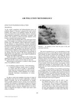
It can be seen from Figure 1 that evaporation is the first
WATER TREATMENT 1313
as hardness. One of the major disadvantages of
wells is that they cannot be observed and there-
fore must be considered as somewhat unreliable.
Frequently it has been experienced in the coun-
try, if a drought has persisted for a few days or a
few weeks (depending on the environment) and
the well has been pumped unusually hard, that the
well will run dry. There is never very much warn-
ing of this kind of occurrence and therefore for a
municipal supply it has the distinct disadvantage
of being considered somewhat unreliable.
2) Springs are similarly unreliable, and have a fur-
ther disadvantage in that they require a rather
elaborate engineering system to capture them and
concentrate them into one manageable system.
Also, springs require rather a large protected area
to ensure that man does not pollute this environ-
ment, thereby rendering the springwater unsafe.
3) Rivers tend also to be a little unreliable, although
they do have the advantage that they can be
observed and to some extent controlled through
dams and other waterflow structures. Thus it can
be seen, if the water level is falling, that a munici-
pality may wish to impose water use restrictions
to conserve water until such time as further aug-
mentation of the supply is received through the
hydrologic cycle. One of the major problems with
a river source is that there is a considerable varia-
tion in the quality of the water. During the high
flow flood period, there is frequently a consider-
able amount of silt and organic material which
is washed off the ground, whereas at other times
of year the water may be relatively clean and
require remarkably little treatment prior to distri-
bution. This of course means that water treatment
facilities must be installed to deal with the worst
possible condition, and at other times of the year
it may not in fact be necessary and therefore the
equipment lies idle.
4) Lakes and manmade reservoirs, due to the nature
of flow through them, have a certain stability
both from the point of view of quantity and qual-
ity. Undoubtedly, water coming from a lake or a
reservoir would require far more elaborate treat-
ment than would water from a well. However,
the extreme reliability and the predictability of
supply may well outweigh the considerations of
cost of treatment. This of course is subject to an
economic feasibility study.
5) Oceans. A good deal of attention is currently
being focused on the desalination of ocean water,
and some attention will be paid to this subse-
quently in this section. It should, however, be
remembered that the ocean is only, economi-
cally available to these communities which are
immediately adjacent to the ocean. This leaves a
very large area of hinterland in most continents
which does not have access to the sea. Thus the
Precipitation
Surface runoff
Infiltration
Per
colation
Transpiration
Evaporation
Snow
Ground water table (G.W.T)
Spring
Lake
Swamp
River
Ocean
G.W.T
Ground water
From land and water surfaces
=Surface runoff and ground-water runoff
Runoff or stream flow
FIGURE 1 Hydrologic cycle (Fair and Geyer, Water Supply and Wastewater Disposal).
C023_006_r03.indd 1313C023_006_r03.indd 1313 11/18/2005 1:32:34 PM11/18/2005 1:32:34 PM
© 2006 by Taylor & Francis Group, LLC
1314 WATER TREATMENT
desalting of sea water as a major water source has
a restricted application to small islands and those
coastal stretches of countries where fresh water
reserves are either not available or not reliable.
6) Recycled water. A considerable amount of research
has been undertaken in the United States and else-
where for the renovation of treated wastewater for
the purposes of returning it directly into the potable
supply. Some rather complex chemical and physi-
cal processes are required to make this a satisfactory
process, and the details of many of these processes
will be described subsequently in the next section
of this chapter.
PHYSICAL TREATMENT
The items of treatment described under this section will be
only those which alter the physical properties of the water
or represent a unit process which is physical in nature. All
of the processes described may be used individually, collec-
tively or in any combination, in order to accomplish a prede-
termined water quality.
Screens
Whatever the source of water, it is necessary to insert some
kind of screen in the system in order to prevent the passage
of solids into the subsequent steps of water treatment. If
the source of water is simply a well, the screens tend to be
simply designed to prevent the admission of sand from the
water-bearing strata into the pumping system. Where water
supply is drawn from rivers or lakes, the intakes usually have
to be screened and built of corrosion-resistant materials in
order to prevent the admission of fish or logs or any other
undesirable solids into the system. Intake screens are usually
provided with openings approximately equal to one and one-
half to two times the area of the intake pipe. The purpose of
this is to ensure that the velocity through the screens is suf-
ficiently low to prevent jamming of the screens. On occasion
other screens are required as a backup system within the
water treatment plant.
In some locations where it is found that seasonally algal
blooms become a nuisance, a new type of screening known
as microstraining has been introduced. Microstrainers are a
very fine weave of stainless steel wire with apertures suffi-
ciently small to prevent the passage of the microscopic algae
which is normally found in an algal bloom. Such a screen-
ing system is normally only required on a seasonal basis
and in certain locations where these problems are prevalent.
Microstraining is conducted at such a very small diameter
orifice that it is sometimes considered to be a part of a filtra-
tion process.
Coagulation
Although the basis of coagulation is in fact chemical treatment
and will be discussed in the next section, the coagulation
process itself (sometimes referred to as flocculation) is
accomplished by a physical process involving the gentle agi-
tation of the fluid which allows the small suspended particles
to collide and agglomerate into heavier particles or flocs and
settle out. Flocculation or coagulation is the principle used in
the removal of turbidity from water. It will be shown subse-
quently that colloidal or very finely divided material will not
settle very rapidly. Various processes have been employed
to accomplish flocculation. Some of these are; diffused air,
baffles, transverse or parallel shaft mixers, vertical turbine
mixers, to mention but a few.
The most common type of flocculator used today is the
paddle type, the other methods having shown some disad-
vantage such as being too severe for the fragile floc, or being
too inflexible, or being too costly to operate. Horizontally
mounted paddles, either located transverse or parallel to the
floor, consist of a shaft with a number of protruding arms
on which are mounted various blades. The shaft rotates at a
very slow rate of 60 to 100 rpm, causing a very gentle agita-
tion which results in the flocculation of the particles. The
time required for the flocculation process is very carefully
controlled and strongly related to the dosage of chemical
which is used. The chemicals used and the chemistry of this
process will be described later.
Prior to the flocculation step which has just been
described, occurs a flash mixing step when the chemicals
are added and mixed very rapidly at high speed to get uni-
form distribution of the chemical in the stream. A variety of
devices are used for this rapid mixing operation; frequently
one of the most common includes the low lift pumps which
are usually located adjacent to the intake where the water is
lifted up into the treatment plant. Here of course the chemi-
cals must be pumped into the pump casing at a higher pres-
sure than the pump is producing, and the mixing takes place
in the casing of the pump.
Other devices frequently used are venturi flumes, air jets,
paddles, turbines, propellers, the latter being one or the most
favored and most widely used of the rapid mixing devices.
It usually is composed of a vertical shaft driven by a motor
CASING
WET
WELL
SCREEN
INTAKE
SCREEN
SANDY STRATA
(I) WELL SCREEN (II) LAKE OR RIVER SCREEN
FIGURE 2
C023_006_r03.indd 1314C023_006_r03.indd 1314 11/18/2005 1:32:34 PM11/18/2005 1:32:34 PM
© 2006 by Taylor & Francis Group, LLC
WATER TREATMENT 1315
on which one or more propeller blades are mounted. Baffles
are frequently used to reduce the vortexing about the propel-
ler shaft. Vortexing hinders the mixing operation. Detention
periods are usually of the order of one to five minutes, usu-
ally at the lower end of this range. Considerable study has
been done on the baffling arrangement in a flash mixing
unit, and a variety of arrangements have been shown to be
successful.
Sedimentation
Sedimentation or settling may be accomplished by a variety
of means and mechanisms, depending on the material which
is to be settled from the liquid.
Discrete settling This type of sedimentation is primarily
concerned with the settling out of non-flocculent discrete
particles in a fairly dilute system. The primary feature of
this type of settling is that the particles do not flocculate and
therefore their settling velocity and particle size remain the
same throughout the period of settling. It will be seen later
that this is quite different from other forms of settling.
The particles in discrete settling will accelerate until the
fluid/drag reaches equilibrium with the driving force acting
on the particle. In other words, the resistance of the water
is equal to the accelerating force of gravity of the particle.
When this velocity is reached, it will not increase. This is
known as the terminal settling velocity, and it is normally
achieved quite rapidly. The loading rate which is used fre-
quently for the design of a settling tank is known as the over-
flow rate and may be expressed in cubic feet per square foot
per day based on the area. It can be seen that cubic feet per
square foot per day is in fact the same as feet per day, or in
fact a simple velocity. This velocity is defined as the set-
tling velocity of the particles which are removed in this ideal
basin if they enter at the surface.
Overflow rates or surface loadings of 150 gallons per
day per square foot of tank surface are not unusual where
the settling and sand, silt or clay are being accomplished by
plain sedimentation.
Flocculent settling The primary difference between this
type of settling and the previous one is that in a flocculent
system the larger particles subsiding at a slightly higher rate
CHEMICAL
FEED
HIGH SPEED
PROPELLER
PADDLE
ROTATI O N
FLASH MIXING UNIT
FLOCCULATOR
FIGURE 3
OUTLET
WEIR
OUTLET
IN LET
SLUDGE
HOPPER
SLUDGE
COLLECTOR
CHAIN
SLUDGE
MIXING ZONE
INLET
RAW
WATER
(Accelator by Infilco)
CIRCULAR COMBINATION
SETTLING FLOCCULATOR
LONGITUDINAL SETTLING
TA N K
FIGURE 4
C023_006_r03.indd 1315C023_006_r03.indd 1315 11/18/2005 1:32:34 PM11/18/2005 1:32:34 PM
© 2006 by Taylor & Francis Group, LLC
1316 WATER TREATMENT
Flocculent settling
path
Discrete settling
path
inlet
Zone settling
Combined Settling Pattern
outlet
FIGURE 5
Settling
Screening
Biological
Growth
Filtration Phenomena
FIGURE 6
will overtake and coalesce with smaller particles to form
even larger particles, which in turn increase the overall set-
tling rate. Clearly, the greater the liquid depth, the greater
will be the opportunity for this type of contact. There is no
mathematical relationship which can be used to determine
the general effect of flocculation on sedimentation, and
empirical data is still required by studying individual labora-
tory cases. As a result, in flocculent settling the removal of
suspended matter depends not only on the clarification rate
but also on the depth.
This is one of the significant differences between non-
flocculent and flocculent settling.
Zone settling The previous two types of settling described
have one property in common, and that is that they both
deal with dilute suspensions. Zone settling, on the other
hand, deals with very concentrated suspensions where it is
assumed that one particle will in fact interfere with the set-
tling rate of another particle. It is clear that in the type of dis-
crete settling, where the particles are somewhat non-reactive
and usually quite dense such as sand, the difference between
dilute suspensions and concentrated or hindered suspensions
is less apparent, so the zone settling phenomenon is usually
considered for the flocculating materials. When the particles
reach the vicinity of the bottom of the settling tank, a more
concentrated suspension zone will be formed and the settling
particles will tend to act in concert and reduce the overall
rate of subsidence.
It can clearly be seen that in a water treatment plant,
particularly if coagulation is applied to remove turbidity, all
three types of settling will occur and any settling tank which
is designed must take into account all three types (Figure 5).
Filtration
As described earlier, it has been found even in the early
Egyptian days that passing water through sand resulted in a
reduction in suspended and colloidal matter, and resulted in a
further clarification of the water. Water which is on occasion
extremely turbid should, of course, first of all be treated by
some coagulation or settling or combination of both. However,
water which is normally not too turbid may be directly applied
to filters or water which has previously been treated by sedi-
mentation and/or coagulation may also be applied to filters to
provide the final polishing and the production of clear, aes-
thetically acceptable water.
The filtration process actually consists of three phenom-
ena occurring simultaneously (Figure 6) .
Settling takes place in the small settling basins which
are provided between the particles. Screening takes place
where particles which are larger than the interstices will
be retained simply physically because they cannot pass
through. And finally, a biological action takes place through
bacterial growth which may occur on the particles of the
filter which may occur on the particles of the filter which
grow at the expense of the soluble organic carbon passing
through in the water. This latter phenomenon is not a very
satisfactory way of removing organic carbon, because it
does tend to plug up the filter fairly rapidly and reduce its
effectiveness.
Filters have been developed through the ages through a
series of steps which are mainly related to their operating
characteristics or the material which is used as a filtering
medium.
Slow sand filter The slow sand filter is, as it suggests,
a process whereby water is allowed to pass very slowly
through the system at rates of 2.5 to 7.5 million gallons per
acre per day.
Although this type of filter has been used traditionally
and has been very effective in the past, it has certain operat-
ing disadvantages in that it cannot readily be cleaned. While
some of these filters are still in use in some parts of the
Orient, in Europe and North America, where labor tends to
be more costly, other types of filters have been developed.
When the difference in water level between the outlet and
the water over the filter becomes too great, the filter is taken
out of service and the top inch or two of sand is removed
from the bed and may or may not be replaced with fresh sand
Rapid sand filter A far more popular and common process
for the filtration of water is the rapid sand filter. Instead
of sitting on a sand bed of approximately three feet, as is
the case in the slow sand filter, the bed is twelve to thirty
inches thick and supported on a layer of gravel or other
coarse grain, heavy material six to eighteen inches thick.
Filtration rates on the rapid sand filter are of the order of
three to four gallons per square foot per minute. Occasionally
C023_006_r03.indd 1316C023_006_r03.indd 1316 11/18/2005 1:32:34 PM11/18/2005 1:32:34 PM
© 2006 by Taylor & Francis Group, LLC
before the filter is put back into operation (Figure 7) .
WATER TREATMENT 1317
a plant is designed to operate at two gallons per square foot
per minute, but provided for an overload when necessary
(Figure 8) .
The cleaning of the rapid sand filter, instead of throw-
ing the filter out of service, is accomplished by simply
backwashing. This is accomplished by passing clean water
backwards through the filter at a high velocity. This velocity
should not be greater than the terminal settling velocity of
the smallest particle of sand which is in the filter which is
not to be washed over the side. Through this mechanism the
sand bed is expanded and the sand is lifted and floated while
the particles rub mechanically against one another and wash
off the foreign material. The dirty water is washed away in
drains. After this has been conducted for a few moments, the
filter is allowed to go back into service and the head loss is
now smaller so the rate of flow through the filter is increased
once more.
Pressure filters Whereas the rapid sand filter is indeed a grav-
ity filter, a pressure filter is somewhat the same type of system
only pressure is applied to the water to pass it through the
filter. The most common household unit nowadays would be
the swimming pool filter, where the water is pumped vertically
through the sand and the filter, and when the head loss through
the filter becomes excessive as registered on the pressure
gauge, the operator will reverse the flow through the filter,
accomplishing the backwash described above
(Figure 9).
Diatomaceous earth filter Diatomaceous earth is the silicious
residue of the bodies of diatoms which were deposited in past
geological ages and now form extensive beds where they are
mined. The earth is processed and ground, and the silica par-
ticles are extremely irregularly shaped and thus provide a very
good porous coating. The diatomaceous earth filter was devel-
oped by the army for field use to remove certain chlorine-
resistant organisms responsible for dysentery.
BACKWASH
WATER
OUT
RAY WATER
IN
SAND
GRAVEL
FILTERED
WATER OUT
BACKWASH
WATER
IN
PRESSURE FILTER CUTAWAY
FIGURE 9
WASH WATER
TROUGHS
EXPANDED
SAND
GRAVEL
BACKWASH WATER
FILTERED EFFLUENT
GRAVEL
SAND
RAPID SANDFILTER
(a) FILTERING
(b) BACKWASHING
FIGURE 8
FILTER
CAKE
WASTE
FOR WASH
WATER
PRECOAT
POT
FILTERED
WATER
BODY
FEEDER
RAW WATER
FEEDER
DIATOMACEOUS EARTH FILTER
FIGURE 10
HEAD
LOSS
CLARIFIED
WATER
OUTLET
SAND
5 FEET
3 FEET
SLOW SAND FILTER
FIGURE 7
C023_006_r03.indd 1317C023_006_r03.indd 1317 11/18/2005 1:32:35 PM11/18/2005 1:32:35 PM
© 2006 by Taylor & Francis Group, LLC
1318 WATER TREATMENT
The filter medium is supported on a fine metal screen
or a porous material. There are three steps in the filtration
cycle. There are three steps in the filtration cycle. First of all,
the deposit of a pre-coat, which is a thin layer of diatomite
deposited on the filter element. The second step is the actual
filtration and the body feed addition. The reason why body
feed is continually added to the filter is to reduce the amount
of clogging that occurs at the surface. This also permits sig-
nificantly longer filter runs. The third step, when the pres-
sure drops or the filtration rate reaches such a low very thin
film over or under the source of irradiation. Commercial
equipment is currently being developed for the individual
water supply of the small household or institution, and is
gaining some acceptance in some quarters. The irradiation
of water by ultra-violet light of suitable wave-lengths for a
proper period of time will kill bacteria, spores, molds, and
viruses and in fact all microorganisms. The bactericidal
wave-lengths extend from about 2000 to 2950 Å (angstrom
units) with a maximum effect around 2540 Å.
CHEMICAL TREATMENT
The unit operations of chemical coagulation, precipitation,
ion exchange and stabilization all produce change in the
chemical quality of the water. Some of these are aimed at the
removal of the suspended and colloidal substances, others
are aimed at the removal of dissolved substances. Finally,
some chemicals are simply added for their own sake, but
these will not be discussed in this section.
To understand some of the basic chemistry of the treat-
ment processes, it is first of all essential to understand a
phenomenon known as chemical equilibrium and reaction
velocities. An analogy might be considered as the physical
equilibrium between ice and water.
Ice Water
Add Heat
Remove heat
If the ice-water system is maintained at 0°C, then molecules
of water are transferred from the solid to the liquid state
and back again at the same rate. The addition of heat or the
removal of heat from the system will result in the equilib-
rium moving in one direction or the other. The same princi-
ples might be applied to what is known as ionic equilibrium,
which, like molecular equilibria, are subject to a shift under
given stresses.
As an example, we might consider pure water
H
2
O
U
H
ϩ
ϩ OH
Ϫ
.
Certain stresses will give rise to an increase in hydrogen ion
concentration (H
ϩ
). The expression of this shift is a reduction
in pH, whereas an increase in the OH
Ϫ
concentration brings
about an increase of pH. One of the most important equilib-
ria which exists in natural waters is the relationship between
carbon dioxide and carbonate ion, which is shown in the fol-
lowing four equilibrium expressions.
CO
2
(gas)
U
CO
2
(solution) (1)
CO
2
(solution) ϩ H
2
O
U
H
2
CO
3
(2)
H
2
CO
2
U
H
ϩ
ϩ HCO
3
Ϫ
(3)
HCO
3
Ϫ
U
H
ϩ
ϩ CO
3
Ϫ
. (4)
FIGURE 11
Filter
Backwash
High density
Small particles
Medium density
Low density
Large particles
Cosmlc Gamma Rays
Rays X Rays
Ultra Violet Visible Light
Infra Red
Radio Waves
10
–4
10
–2
10
2
10
4
10
6
10
8
10
10
Ultra Violet Visible
Bacteriacidal
Max. Bacteriacidal Violet
Green
Red
Infra
Red
0
1000
2000
3000
4000
5000
6000 7000
8000
ELECTROMAGNETIC SPECTRUM
Light
FIGURE 12
C023_006_r03.indd 1318C023_006_r03.indd 1318 11/18/2005 1:32:35 PM11/18/2005 1:32:35 PM
© 2006 by Taylor & Francis Group, LLC
WATER TREATMENT 1319
The equilibrium of the first of these equations is purely
physical, since the solubility of gas and water is determined
by the pressure of that gas and the temperature and a number
of other physical parameters.
Coagulation
The principle function of chemical coagulation is known as
destabilization, aggregation, and binding together of col-
loids. Alum, or aluminum sulphate, (Al
2
(SO
4
)
3
· 18H
2
O) is
one of the most common coagulants which may be added
to a water system. Such a coagulant possesses tiny positive
charges and therefore has the ability to link together with
negatively charged color or turbidity particles by mutual
coagulation. Alum also reacts with the natural alkalinity
(carbonate- bicarbonate system) of the water to produce a
precipitate which is usually thought to be aluminum hydrox-
ide. If the reaction takes place with natural alkalinity, it may
be expressed as follows:
Al
2
(SO
4
)
3
· X H
2
O 3Ca(HCO
32
) → 2Al(OH)
3
ϩ 3CaSO
4
ϩ X H
2
O ϩ6CO
2
.
In the event that there is insufficient natural alkalinity for
this to occur, then calcium oxide (lime) may be added to
create the same effect. Because this system is very poorly
understood, the optimum dosage required in practice has to
be done by trial and error through a series of tests known as
jar tests.
In these jar tests, the flash mixing and flocculation steps
described previously are stimulated at various concentra-
tions of alum and the clarification which takes place and the
reduction of turbidity and the rate at which the floc settles
are all observed in order to determine the optimum dosage
of coagulant. If too much coagulant is added, then the col-
loidal system which is primarily negatively charged will
become supersaturated by the aluminum system which is
primarily positively charged and the suspension will become
restabilized and this can be observed by conducting jar tests
over a wide range of concentrations of coagulant.
The reason why alum is so generally used is that it is
highly effective over a wide pH range in waters of vastly
different chemical make-up. Other materials such as ferrous
sulphate are occasionally used to increase the settling rate of
plankton and thus increase the time of the filter run, making
the filter process more efficient.
Precipitation
There are two important processes which are associated with
precipitation in the treatment of water. One is the reduction
of hardness (calcium and magnesium) and the other is the
reduction of iron and manganese.
Water Softening The lime-soda-ash process involves the
addition of Ca(OH)
2
and Na
2
CO
3
to water. The reactions
which occur are as follows:
Ca(HCO ) Ca(OH) 2CaCO 2H O
32 2
Lime
3
+
2
ϩϩ→
(1)
Mg(HCO ) Ca(OH) MgCO CaCO 2H O
32 2 3 3 2
ϩϩϩ→
(2)
MgCO Ca(OH) Mg(OH) CaCO
32 23
ϩϩ→
(3)
CaSO Na CO CaCO Na SO
42
Soda Ash
324
ϩϩ
3
→ .
(4)
In this reaction it can be seen that the lime is added to precipitate
the carbonate hardness, while the soda ash provides the car-
bonate ion to precipitate the non-carbonate hardness.
Precipitation of Iron and Manganese Normally, iron and
manganese are only highly soluble if they are in their ferrous
(Fe
2 ϩ
) and manganous (Mn
2 ϩ
) forms. Normally, these two
metals will only occur in this form if there is an absence of
dissolved oxygen. However, on occasions when the water is
particularly acid, such as might occur in mine drainage areas,
the metals may remain in solution even though a very high dis-
solved oxygen is present. Under these circumstances, aeration
is frequently sufficient to drive off the surplus carbon diox-
ide, increase the pH and bring about a natural precipitation
of these materials in their ferric and manganic form. In order
to catalyze or accelerate this reaction, the water is frequently
caused to trickle over coke or crushed stone, or to flow upward
through some contact material. This allows deposits of iron
and manganese to accumulate on the surfaces and catalyze the
further precipitation of ferric and manganic oxides.
If the pH of the system is forced to values higher than
7.1, the positively charged ferric hydroxide particles may be
Drive
Motor
Control
Stirrer
FIGURE 13 Jar test equipment—coagulant dosage varied in each jar to deter-
mine optimum concentration.
C023_006_r03.indd 1319C023_006_r03.indd 1319 11/18/2005 1:32:35 PM11/18/2005 1:32:35 PM
© 2006 by Taylor & Francis Group, LLC
1320 WATER TREATMENT
adsorbed on the negatively charged calcium carbonate par-
ticles and a stable colloidal suspension may result. Iron and
manganese are objectionable constituents of water supplies
because they impart a brown colour to laundry goods and
frequently will stain household plumbing fittings.
Precipitation of iron and manganese can also be satisfac-
torily accomplished by using the lime-soda-ash process as
described above for softening.
Ion Exchange
Ion exchange units are most frequently used for softening
waters, but are also used by certain industries for the production
of de-ionized water. This is quite common in the brewery
industry, where an attempt is made to strip the water down
to its most pure constituents so that water in one part of the
world is similar to water in other parts of the world. Following
de-ionization, breweries and often distilleries will reconsti-
tute the water so that the water used for the production of a
certain type of beer will be the same all over the continent
and not have the variations which were characteristic of beers
when native waters were used for their production.
The chemistry of the ion exchange process is shown below,
where a cation resin which will exchange the sodium (Na
ϩ
)
for the calcium and magnesium (Ca
2 ϩ
, Mg
2 ϩ
). When the resin
is saturated with calcium and magnesium, a regeneration is
required such as is used in household water softening units,
when a very strong brine solution is forced back through the
resin and in turn displaces the calcium and magnesium into the
backwash line and restores the sodium on the resin for further
softening.
Softening Na
Ca
Mg
(HCO ) Ca
SO
Cl Mg
2
32
4
2
ϩ →
⎡
⎣
⎢
⎢
⎢
⎤
⎦
⎥
⎥
⎥
(1)
R
2NaHSO
Na SO
2NaCl
4
24
ϩ
⎡
⎣
⎢
⎢
⎢
Regeneration
Ca
Mg
R 2NaCl Na R
Ca
Mg
Cl
22
⎤
⎦
⎥
→
⎤
⎦
⎥
ϩϩ
(2)
Desalination
Although the principles of desalination were fully known in
Julius Caesar’s time, the energy requirements of this process
are presently so high that these will be usually considered as
a last resort after all other water sources have been explored.
Water quality is frequently referred to as fresh, brackish, sea
water or brine. Fresh water normally contains less than 1000
mg/liter of dissolved salts, while brackish water ranges from
1000–35,000 mg/liter of dissolved salts. Sea water contains
35,000 mg/liter of dissolved salts, whereas brine contains very
much more from salt water by a semi-permeable membrane,
the fresh water will tend to flow into the salt water to equal-
ize the concentration of salts on both sides of the membrane.
Bearing in mind that the membrane will not allow the salts to
pass back, it is clear that a certain pressure which is known
as the osmotic pressure is forcing the fresh water through
to the brine side of the membrane. If a force greater than
this osmotic pressure is applied on the sea water side, then
fresh water will flow backwards through the semi-permeable
membrane at a rate proportional to the incremental pressure
over the osmotic pressure. In practice, quite high pressures
are required in order to get a useful volume of water to pass
through the membrane—such pressures as 40–100 kg per
square centimeter. This has been shown to work for waters
of fairly high dissolved solids, but the structural properties of
the membranes must be fairly well developed and of course
the membranes must be very well supported. Membranes
used for this type of process are frequently cellulose acetate
or some derivatives thereof. The power requirement for this
process is considerably less than electrodialysis, but it is a
S.W.
14
IN
18
HEAT EX.
10
19
11
24
28
13
16
VAPORIZATION-COOLING
STEAM
GENERATOR
SOLUTION
HEAT EX.
VENT
27
ABSORBER
CONC
WATER
SEA
OUT
FRESH
WATER
OUT
FIGURE 14 Conventional multistage
flash evaporation – MSF evaporating
and cooling of hot feed brine (vertical
arrows down) on left side at succes-
sively lower pressures after heating
to highest temperature in prime heater
(PH) at top; vapors (horizontal ar-
rows) from MSF, passing to preheat
the sea water by condensation-heating
on right side; fresh water condensate
passing stagewise from top to dis-
charge at bottom; additional sea water
coolant (dotted line) rejecting heat in
lower stages, withdrawing of vapors
from prime heater to be condensed in
half-stage (dashed lines) increasing
the production of fresh water.
C023_006_r03.indd 1320C023_006_r03.indd 1320 11/18/2005 1:32:35 PM11/18/2005 1:32:35 PM
© 2006 by Taylor & Francis Group, LLC
WATER TREATMENT 1321
FEED
REJECT
PERMEATE
MORE
CONCENTRATED
BRINE
RETURN ENDS
OF FIBERS
PRESSURE
TUBE-STEEL
THOUSANDS OF “HAIR-PIN”
HOLLOW FIBERS
EPOXY POTTING FILLED
SPACE AROUND ENDS
`OF HOLLOW FIBERS
MAGNIFIED SECTION OF ENDS
OF HOLLOW FIBERS (BOTH
ENDS)
FRESH WATER
PRODUCT
SALINE WATER
FIGURE 17
Saline
Water
Feed
+
+
+
+
–
–
–
–
Selective
lon
Membrane
Brine
Fresh
Water
Brine
Electrodialysis
FIGURE 16
about further cooling. Close to freezing ice crystals will
form with a brine coating, and washing of these crystals will
yield fresh water from the washed ice. Small plant appli-
cation appears to be feasible at the moment. Considerable
development work on this was done by the Technion Institute
in Israel.
A Secondary Refrigerant Process This involves the use of
a second hydrocarbon refrigerant, such as butane, that will
not mix with water. A great deal of care must be exercised
S.W.
14
IN
18
HEAT EX.
10
19
11
24
28
13
16
VAPORIZATION-COOLING
STEAM
GENERATOR
SOLUTION
HEAT EX.
VENT
27
ABSORBER
CONC
WATER
SEA
OUT
FRESH
WATER
OUT
FIGURE 15 Vapor reheat with vapor
recompression by absorption (from
US Patent 3,288,686). Vapor reheat
MSF, vapors formed in low pressure
stage pass to Absorber, 27, and are ab-
sorbed in the hydrophilic liquid from
solution heat exchanger, which cycles
through heat exchanger to evaporator
or generator, 28, for concentration at
higher pressure. Vapors leave at higher
pressure to half-stage, 19, to supply
prime heat to evaporator.
process which offers considerable promise for the desalina-
tion of brackish waters.
The Vacuum Freezing Process Cooled saline water passes
into a low pressure chamber where flash evaporation brings
C023_006_r03.indd 1321C023_006_r03.indd 1321 11/18/2005 1:32:36 PM11/18/2005 1:32:36 PM
© 2006 by Taylor & Francis Group, LLC
1322 WATER TREATMENT
REFRIGERANT
COILS(HEAT
REMOVAL)
VAPOR COMPRESSOR
DRIVER
VAPOR
COMPRESSOR
IMPELLOR
SCRAPER
DRIVE
WASH WATER DISTRIBUTOR
ON SCRAPER
TO AIR
REMOVAL
ICE DECANTER
BRINE
OUT
FRESH WATER OUT
SEA
WATER
IN
BRINE
OUT
HEAT
EXCHANGER
PRODUCT WATER
FEED WATER
ICE-BRINE SLURRY
FREEZER-
EVAPORATOR
FRESH
WATER
FREEZER
AGITATOR
AGITATOR
DRIVE
ROTATING
PERFORATED
ICE MELTING
TRAY
AMMONIA
REFRIGERATOR
VAPOR
VAPOR MIST
SEPARATOR
BRINE
ICE RISING
SCREEN
TO AIR
REMOVAL
ICE
MELTER
SCRAPER
ICE
FIGURE 18 Vacuum freezing process
COMPRESSOR
TO AUXILIARY
EQUIPMENT
SPRAY
CONDENSER
HEAT
EXCHANGER
NOTE : BOTH BUBBLES
AND CRYSTALS
ARE SHOWN
BUTANE
CONDENSATE
RETURN
FREEZER
BRINE
OUT
SEA
WATER IN
FRESH WATER OUT
ICE-FRESH WATER
SLURRY
ICE-
BRINE
SLURRY
TO ICE
DECANTER
ICE DECANIER
BRINE FROM
RECYCLE OUTANE
LIQUID BUTANE FOR CONDENSER
CELL IV CELL III CELL II
CELL
ICE
DECANTER
FIGURE 19 Secondary refrigerant freezing process
C023_006_r03.indd 1322C023_006_r03.indd 1322 11/18/2005 1:32:36 PM11/18/2005 1:32:36 PM
© 2006 by Taylor & Francis Group, LLC
WATER TREATMENT 1323
here to ensure that the product is stripped of butane; oth-
erwise serious explosion hazards exist. It has a low energy
input and has minimized corrosion and scale-forming prop-
erties. However, so far this process has not been examined
on a very large-scale basis.
Other Processes There are a number of other processes
which are being considered for desalination, such as solar dis-
tillation, but so far this has been restricted to use on a very
small scale such as survival kits. Ion exchange, such as was
described previously, has some potential here but it is very
much limited down to approximately 3000 mg/liter solids.
A hydrate process has been considered where propane is added
to form a hydrate and react with the water, leaving the salt
behind. Then the propane hydrate is decomposed to recover the
propane and the water; this one is rather difficult to handle.
Disinfection
As mentioned earlier, water has long since been identified
as a means of distributing pathogenic organisms among
society. The purpose therefore of disinfecting water sup-
plies is to prevent the spread of water-borne disease by
destroying pathogenic organisms. Most of the physical
and chemical treatment processes described previously
will remove most of the micro-organisms to some extent.
However, very small numbers of microorganisms which
are viable and pathogenic are all that are required to bring
about disastrous epidemics. Thus, disinfection is consid-
ered to be a necessary final step before treated water is
delivered to a municipal system. This may not be the case
in certain industrial supplies.
A physical process for disinfection was previously
described using ultra-violet irradiation. Other forms of
chemical disinfectant are the halogens such as chlorine, bro-
mine, iodine, and the powerful, unstable oxidant, ozone. In
North America chlorination is the most common of the dis-
infectant processes used, for two reasons. Firstly, it is fairly
simple to handle, can be manufactured inexpensively in bulk
and delivered to the site, can be applied under fairly con-
trolled conditions, and can maintain a measurable residual
in the water supply to indicate safety at all points on a water
distribution system. The first attempt at continuous chlorina-
tion of a public water supply was made in England during
1904, and subsequently in 1908 in Jersey City, New Jersey,
USA. There are certain disadvantages of chlorination, in
that a high residual chlorine will bring about a taste which
is unacceptable to many people; and chlorine furthermore
will react with certain micro-constituents of water, such as
phenols, to bring about substantial odors (chlorophenols)
quite out of proportion to the concentration of the causative
chemicals. The addition of chlorine to water releases a group
of substances, all of which have some disinfecting proper-
ties. The substances so released are:
1) hypochlorite ion(OCl);
2) hypochlorous acid (HOCl);
3) monochloramine (NH
2
Cl);
4) dichloramine (NHCl
2
);
5) nitrogen trichloride (NCl
3
);
6) organic compounds containing chloride; and
7) chlorine dioxide (ClO
2
).
Hypochlorite ion and hypochlorous acid are known col-
lectively as free available chlorine residuals. The follow-
ing substances are known as chloramines: NH
2
Cl, NHCl
2
,
NCl
3
, and organic chlorine compounds. The chloramines
are brought about by the reaction of hypochlorous acid with
ammonia
NH
3
ϩ HOCl → NH
2
Cl ϩ H
2
O
NH
2
Cl ϩ HOCl → NHCl
2
ϩ H
2
O
NHCl
2
ϩ HOCl → NCl
3
ϩ H
2
O.
The process which brings about the various chloramines
are shown above. Chlorination is applied in a series of dif-
ferent forms as follow:
Superchlorination This process represents the addition of
very high concentrations of chlorine which are intended to
oxidize not only the pathogenic and potential pathogenic
microorganisms in the system, but also to oxidize those
organic compounds which might bring about taste and odor.
Following superchlorination, a step involving dechlorina-
tion which involves the addition of sulphur dioxide, sodium
bisulphite, or sodium sulphite or some similar reducing
agent. The bisulphite is frequently used in practice because
it is cheaper and more stable.
If there is any amount of ammonia naturally present
in the water, a strange phenomenon will occur such as
shown above in the graph. On the initial part of the graph,
labelled 1 to 2, the ratio (molar) of chlorine to ammonia
is less than one and the residual chlorine is essentially all
monochloramine. In the next section, between 2 and 3, the
oxidation of ammonia and reduction of chlorine continue
until the complete oxidation reduction occurs at point 3.
At this point once again, all the residual chlorine is in the
Chlorine Residual
Chlorine Dosage
1
2
3
FIGURE 20
C023_006_r03.indd 1323C023_006_r03.indd 1323 11/18/2005 1:32:36 PM11/18/2005 1:32:36 PM
© 2006 by Taylor & Francis Group, LLC
1324 WATER TREATMENT
form of monochloramine. Beyond point 3, all chlorine
added remains in solution. This phenomenon is known as
break-point chlorination, and in order to ensure satisfac-
tory disinfecting properties chlorination must go beyond
the break-point 3 on the curve.
In certain instances, such as when phenols are present
in the water, small concentrations of free available chlorine
will combine with the phenols, forming chlorphenols which
produce a distinctive taste and odor at very, very small con-
centrations. When this occurs, chlorine dioxide is frequently
used as a disinfecting agent as this does not react with the
phenols but in fact destroys them.
Other substances which are used for disinfecting pur-
poses are the other halogens such as bromine and iodine,
although these are not commonly used in water supplies.
Occasionally they have been used in swimming pools for
similar purposes.
Ozone is a particularly effective disinfectant, but it has
certain disadvantages in that it must be manufactured on the
site, using fairly sizeable and expensive capital equipment.
No residual can be maintained due to the instability of the
substance, and the methods of detection are rather imperfect.
However to compensate for this, the disinfecting properties
of ozone are considerably greater than chlorine.
VOC REMOVAL
Treatment of Volatile Organic Compounds Found
in Groundwater Sources
With the advent of technological advances in testing of water
supplies and concerns regarding possible contamination
of groundwater sources, many water supply systems have
focused on the treatment of Volatile Organic Compounds
(VOC’s). VOC’s are man-made chemicals, some of which
have been shown to be carcinogenic. VOC’s are generally
found in industrialized settings where substances such as
cleaning fluids, degreasers or solvents have been disposed
of improperly.
The treatment of VOC’s utilizing conventional water
treatment techniques involving flocculation, sedimentation
and filtration are relatively ineffective at reducing VOC con-
centrations. VOC’s may be treated by either packed tower
aeration (air stripping) or granular activated carbon (GAC)
absorption. Details of the two treatment techniques are as
follows:
Packed Tower Aeration (Air Stripping)
Aeration is the process where air and water are brought into
contact for the purposes of transferring volatile substances
from water to air. This process is commonly referred to as
air stripping. Air stripping basically involves the transfer
of dissolved gas molecules from the liquid phase to the gas
phase. There are two major factors which determine the
removal efficiency of various volatile compounds by air
stripping; 1) the ratio of concentration of VOC’s in the gas-
eous phase to the concentration of VOC’s in the aqueous
phase at equilibrium, and 2) the rate at which equilibrium
is obtained.
Numerous types of aeration devices have been used
where air stripping can occur. Some of these alternatives
involve diffused aeration, spray aeration and water fall
aeration.
In packed towers or stripping towers, water flows down-
ward by gravity and air is forced upward. The tower is filled
with various forms of packing material which serves to
continuously disturb the liquid flow, creating and improving
the air-to-water interface. Packed towers typically have void
volumes in excess of 90 percent which allows for a large
liquid-air interface and minimizes the pressure drop through
the column, an operating cost consideration. Packed towers,
which are currently in service, have provided VOC remov-
als in the 95–99.9 percent range. A schematic of a typical
There are three major design factors controlling the mass
transfer of VOC’s from water to air.
Packing depth —is the primary factor influencing removal
efficiency. Increasing the packing depth will increase the
removal efficiency of the tower.
Tower diameter —controls the liquid loading rate as
measured in gallons per minute per square foot, (GPM/
sq. ft.). The lower the liquid loading rate, the greater the
removal efficiency due to the increased air-to-water interac-
tion zone.
Air-to-water ratio —is the most influential parameter
with respect to removal efficiency. Generally, the removal
efficiency increases as the air-to-water ratio is increased.
In stripping towers, packing materials are used to provide
high void volumes together with high surface area. The water
flows downward by gravity and air is forced upward. The raw,
untreated water is evenly distributed on the top of the pack-
ing with either spray or distribution trays and the air is forced
through the tower by either blowers or induced draft fans.
Many options exist for packings involving a variety of
shapes and materials. Packings are available in plastic, metal
and ceramic. Plastics are best suited for water treatment
because of their durability and low cost.
Since the mass transfer of VOC’s is basically accom-
plished by passing significant quantities of air through a
fixed quantity of water, the air-to-water ratio can be varied
by either, i) increasing the diameter of the column, or
ii) increasing the air blower capacity. Hence, an optimum
balance of tower diameter and blower size must be evaluated.
Given a specific water loading rate and a packing selection,
the air-to-water ratio determines the height of the stripping
tower required to provide the specified removals.
Various liquid loading rates are evaluated to optimize
the tower diameter versus air pressure drops. Once the tower
diameter is determined, a cost analysis comparing capital
and operating cost is determined. A matrix of air-to-water
ratios and depth of packing is then developed to determine
the optimum design.
C023_006_r03.indd 1324C023_006_r03.indd 1324 11/18/2005 1:32:36 PM11/18/2005 1:32:36 PM
© 2006 by Taylor & Francis Group, LLC
airstripping facility is shown on Figure A.
WATER TREATMENT 1325
EXISTING
WELL PUMP
STRIPPING TOWER
AIR OUT
MIST ELIMINATOR
DISTRIBUTION TRAY
PLASTIC PACKING MEDIA
AIR BLOWERS
TO DISTRIBUTION/STORAGE
VERTICAL
TURBINE PUMP
CLEAR WELL
AIR
WAT
FIGURE A
C023_006_r03.indd 1325C023_006_r03.indd 1325 11/18/2005 1:32:36 PM11/18/2005 1:32:36 PM
© 2006 by Taylor & Francis Group, LLC
1326 WATER TREATMENT
Granular Activated Carbon (GAC)
The removal of VOC’s through adsorption involves passing
the contaminated water through a medium of adsorbent, such
as activated carbon, where the VOC’s will adhere (stick)
to its surface. Adsorbates which could possibly be used to
remove VOC’s from groundwater include granular activated
carbon (GAC) and powdered activated carbon (PAC). GAC
exhibits a wide range of effectiveness in adsorbing various
compounds and generally tends to adsorb high-molecular
weight compounds more readily than low-molecular weight
substances such as VOC’s. However, GAC is currently the
best available adsorbent for the removal of VOC’s.
Powdered activated carbon has been used traditionally
for the removal of trace organics associated with causing
taste and odors in drinking water. PAC typically requires
coagulation and sedimentation facilities to be effective and
is not normally used for groundwater treatment.
GAC has a spectrum of effectiveness like aeration; how-
ever, the process is more complicated and water quality
can have an influence on performance. The adsorption of
VOC’s can be affected by the amount of background organic
carbon, generally measured as total organic carbon. High
background organic content can result in lower adsorption
capacity.
GAC contractors also require regeneration or replacement
when the material becomes saturated with contaminants. The
life of the GAC is dependent upon the concentrations of the
contaminants present, the flow rate through the media and
the required effluent concentrations. GAC contractors have a
reported removal efficiency of 99%. A schematic of a typical
A combination of aeration-adsorption can also be a
highly effective method of reducing VOC levels to very
low concentrations. This combination is quite attractive
when several different types of contaminants are present.
However, the corresponding cost of treatment increases
dramatically.
VOC Treatment with Granular Activated Carbon
(GAC)
GAC treatment can employ either a gravity or pressure
system. The gravity disrepair is generally used in surface
water treatment plants and operates in a manner similar to a
gravity sand filter.
In groundwater treatment systems, a pressure disrepair
(contactor) is generally used and involves a pressurized
vessel which can accommodate flow rates at high pres-
sures and allow direct discharge to an existing distribution
system.
Numerous GAC contactors are currently in use for the
removal of VOCs and a significant amount of data is avail-
able on this form treatment.
GAC contactors would involve vertical steel pressure
vessels which would allow the raw water to enter the top of
the vessel and pass downward through the carbon bed.
The treated water is collected at the bottom of the
vessel utilizing a header-lateral arrangement or a bottom
plate with nozzles. The collected water would then be dis-
infected and discharged to the distribution system for con-
sumption.
Since the contactor is essentially a filter, the vessel would
be equipped with backwashing facilities. The carbon filters
would not require frequent backwashing. The contactor back-
wash waste would be disposed of by discharging to the nearby
holding pond and subsequently to the sanitary sewer system.
Connections would also be provided to readily remove the
spent carbon and to readily install the new material.
As a general rule, aeration is most effective with low-
molecular weight, highly volatile substances, while adsorp-
tion works best with high-molecular weight compounds with
a low solubility. The selection of the treatment alternative is
based on many factors such as the contaminant(s), concentra-
tions of contaminants, groundwater quality, site constraints,
pumping system configuration as well as other factors.
Air stripping facilities, by their nature, require the exist-
ing pumping facilities to be modified as well as the need to
install a second pumping system. Existing pumping systems
must be modified to produce less head (pressure) in order to
direct water to the stripping tower. The tower will dissipate
the energy provided by the well pump as the water passes
through the tower and into the clearwell below. From the
clearwell, the water must be repumped to the water system
for use. As such, the economic feasibility of an air-stripping
facility must account not only for the capital and operating
expenses of the stripping facility, but must also account for
modifications to existing well pump(s) and the costs associ-
ated with repumping the water supply for use.
Unlike an air-stripping facility, a pressurized carbon
contactor does not utilize mechanical equipment as part of
the treatment process. Most often, existing pumping facili-
ties may remain unchanged if a small head loss (which
would result in a slightly reduced flowrate) can be tolerated.
After water is pumped through the contactor, it is discharged
directly to the distribution system for use. As such, GAC
facilities have a major advantage over air strippings due
to ease of operation and the ability to discharge directly to
existing systems without repumping.
There is a move toward privatization of public water
(and wastewater) operations. There are advantages and dis-
advantages associated with this. The Contractor assumes
responsibility for operating results. If a plant has a staff that
is too large or inadequately trained, a for-profit operation can
be expected to introduce greater efficiency in operation. At
times, public office holders have introduced privatization to
show a better municipal financial picture than is the actual
case. The Contractor may not practice proper maintenance
or may try to operate with a staff that is too small. This may
be reflected in poor operating results and the public agency
charged with oversight can be expected to take action if the
public health is threatened. Each case is unique and each
decision to privatize must be evaluated taking into account all
pertinent factors.
C023_006_r03.indd 1326C023_006_r03.indd 1326 11/18/2005 1:32:37 PM11/18/2005 1:32:37 PM
© 2006 by Taylor & Francis Group, LLC
GAC facility is shown in Figure B.
WATER TREATMENT 1327
CONTACTOR 1
(TYP.)
UNDERDRAIN
SYSTEM
(TYP.)
RATE OF FLOW
CONTROL VALVE (TYP.)
BACKWASH WASTE TO
SANITARY SEWER
TO DISTRIBUTION/
STORAGE
CHLORINE
WELL PUMP (TYPICAL)
RAW WATER
CYLINDER OPERATED
BUTTERFLY VALVE (TYP.)
POLISHING FILTER
CONTACTOR 3
CONTACTOR 2
APPROX. 9.5 FT
CARBON DEPTH
CARBON REFILL
CONNECTION (TYP.)
SCHEMATIC FOR CENTRALIZED
GRANULAR ACTIVATED CARBON
TREATMENT FACILITY
10' DIA.
NOTE: CONCEPTUAL SCHEMATIC ARRANGEMENT SHOWN IS FOR P
ARALLEL
OPERATION. ADDITIONAL VALVING WOULD BE REQUIRED FOR
SERIES OPERATION.
FIGURE B
C023_006_r03.indd 1327C023_006_r03.indd 1327 11/18/2005 1:32:37 PM11/18/2005 1:32:37 PM
© 2006 by Taylor & Francis Group, LLC
1328 WATER TREATMENT
WATER SUPPLY AND SANITATION: see COMMUNITY HEALTH
WATER TRANSPORT: see HYDROLOGY; WATER FLOW
REFERENCES
1. Durant, Will, 1954, Our Oriental Heritage , Simon and Schuster Inc.,
New York, p. 132.
2. Baker, M.N., 1949, The quest for pure water, American Water Works
Association, New York, pp. 13, 6, 11.
3. Brown, J.R. and D.M. McLean, 1967, Water-borne diseases: An
historical review, Medical Services Journal Canada , 23 , no. 8,
pp. 1011–1026.
4. Estimates of the water and sewerage industries and utilities division,
Jan. 1956, Business Service Bulletin 136, Business and Defense Ser-
vices Administration, US Department of Commerce.
5. Ackerman, E.A. and G.O. Lof, 1959, Technology in American Water
Development , Johns Hopkins Press, Baltimore.
6. Clark. J.W. and Warren Viessman, 1965, Water Supply and Pollution
Control , International Textbook Company, Scranton.
7. Fair, G.M. and J.C. Geyer, 1954, Water Supply and Wastewater Dis-
posal , Wiley, New York.
8. Steel, E.W., 1960, Water Supply and Sewerage , 4th Ed., McGraw-Hill
Book Company Inc., New York.
9. Michaelides, G. and R. Young, 1986, Provisions in Design and Main-
tenance to Protect Water Quality from Roof Catchments, Advances in
Environmental Science and Engineering , Vol. 5, Gordon and Breach,
New York.
10. Glaze, W.H., 1987, Drinking-water Treatment with ozone, Environ.
Sci. Tech. , 21 .
11. Hoigne, J. and H. Bader, 1988, The Formation of Trichlormethane
(Chloropicrin) and Chloroform in a Combined Ozonation/Chlorination
of a Drinking Water, Water Res. , 22 .
11. Kogelschatz, M., 1988, Advanced Ozone Generation , in Process Tech-
nologies for Water Treatment, Plenum, New York.
12. White, G.C., 1989, Handbook of Chlorination , 2nd Ed., Van Nostrand
Reinhold, New York.
PHILIP H. JONES (DECEASED)
Griffith University
MARK A. TOMPECK
Hatch Mott MacDonald
C023_006_r03.indd 1328C023_006_r03.indd 1328 11/18/2005 1:32:37 PM11/18/2005 1:32:37 PM
© 2006 by Taylor & Francis Group, LLC