1999 HVAC Applications Part 2 ppsx
Bạn đang xem bản rút gọn của tài liệu. Xem và tải ngay bản đầy đủ của tài liệu tại đây (478.96 KB, 27 trang )
7.4 1999 ASHRAE Applications Handbook (SI)
with and without fixed or movable walls around the surgical team
(Pfost 1981). Some medical authorities do not advocate laminar
airflow for surgeries but encourage air systems similar to those
described in this chapter.
Laminar airflow in surgical operating rooms is airflow that is
predominantly unidirectional when not obstructed. The unidirec-
tional laminar airflow pattern is commonly attained at a velocity of
0.45 ± 0.10 m/s.
Laminar airflow has shown promise in rooms used for the treat-
ment of patients who are highly susceptible to infection (Michael-
son et al. 1966). Among such patients would be the badly burned
and those undergoing radiation therapy, concentrated chemother-
apy, organ transplants, amputations, and joint replacement.
Temperature and Humidity
Specific recommendations for design temperatures and humidi-
ties are given in the next section, Specific Design Criteria. Temper-
ature and humidity for other inpatient areas not covered should be
24°C or less and 30% to 60% rh.
Pressure Relationships and Ventilation
Table 3 covers ventilation recommendations for comfort, asepsis,
and odor control in areas of acute care hospitals that directly affect
patient care. Table 3 does not necessarily reflect the criteria of the
American Institute of Architects (AIA) or any other group. If spe-
cific organizational criteria must be met, refer to that organization’s
literature. Ventilation in accordance with ASHRAE Standard 62,
Ventilation for Acceptable Indoor Air Quality, should be used for
areas where specific standards are not given. Where a higher outdoor
air requirement is called for in ASHRAE Standard 62 than in Table
3, the higher value should be used. Specialized patient care areas,
including organ transplant and burn units, should have additional
ventilation provisions for air quality control as may be appropriate.
Design of the ventilation system must as much as possible pro-
vide air movement from clean to less clean areas. In critical care
areas, constant volume systems should be employed to assure
proper pressure relationships and ventilation, except in unoccupied
rooms. In noncritical patient care areas and staff rooms, variable air
volume (VAV) systems may be considered for energy conservation.
When using VAV systems within the hospital, special care should be
taken to ensure that minimum ventilation rates (as required by
codes) are maintained and that pressure relationships between var-
ious spaces are maintained. With VAV systems, a method such as air
volume tracking between supply, return, and exhaust could be used
to control pressure relationships (Lewis 1988).
The number of air changes may be reduced to 25% of the indi-
cated value, when the room is unoccupied, if provisions are made to
ensure that (1) the number of air changes indicated is reestablished
whenever the space is occupied, and (2) the pressure relationship
with the surrounding rooms is maintained when the air changes are
reduced.
In areas requiring no continuous directional control (±), ventila-
tion systems may be shut down when the space is unoccupied and
ventilation is not otherwise needed.
Because of the cleaning difficulty and potential for buildup of
contamination, recirculating room heating and/or cooling units
must not be used in areas marked “No.” Note that the standard recir-
culating room unit may also be impractical for primary control
where exhaust to the outside is required.
In rooms having hoods, extra air must be supplied for hood
exhaust so that the designated pressure relationship is maintained.
Refer to Chapter 13, Laboratories, for further discussion of labora-
tory ventilation.
For maximum energy conservation, use of recirculated air is pre-
ferred. If all-outdoor air is used, an efficient heat recovery method
should be considered.
Smoke Control
As the ventilation design is developed, a proper smoke control
strategy must be considered. Passive systems rely on fan shutdown,
smoke and fire partitions, and operable windows. Proper treatment
of duct penetrations must be observed.
Active smoke control systems use the ventilation system to cre-
ate areas of positive and negative pressures that, along with fire and
smoke partitions, limit the spread of smoke. The ventilation system
may be used in a smoke removal mode in which the products of
Fig. 1 Typical Airborne Contamination in Surgery and Adjacent Areas
7.6 1999 ASHRAE Applications Handbook (SI)
combustion are exhausted by mechanical means. As design of active
smoke control systems continues to evolve, the engineer and code
authority should carefully plan system operation and configuration.
Refer to Chapter 51 and NFPA Standards 90A, 92A, 99, and 101.
SPECIFIC DESIGN CRITERIA
There are seven principal divisions of an acute care general
hospital: (1) surgery and critical care, (2) nursing, (3) ancillary,
(4) administration, (5) diagnostic and treatment, (6) sterilizing
and supply, and (7) service. The environmental requirements of
each of the departments/spaces within these divisions differ to
some degree according to their function and the procedures car-
ried out in them. This section describes the functions of these
departments/spaces and covers details of design requirements.
Close coordination with health care planners and medical equip-
ment specialists in the mechanical design and construction of
health facilities is essential to achieve the desired conditions.
Surgery and Critical Care
No area of the hospital requires more careful control of the asep-
tic condition of the environment than does the surgical suite. The
systems serving the operating rooms, including cystoscopic and
fracture rooms, require careful design to reduce to a minimum the
concentration of airborne organisms.
The greatest amount of the bacteria found in the operating room
comes from the surgical team and is a result of their activities during
surgery. During an operation, most members of the surgical team are
in the vicinity of the operating table, creating the undesirable situa-
tion of concentrating contamination in this highly sensitive area.
Operating Rooms. Studies of operating-room air distribution
devices and observation of installations in industrial clean rooms
indicate that delivery of the air from the ceiling, with a downward
movement to several exhaust inlets located on opposite walls, is
probably the most effective air movement pattern for maintaining
the concentration of contamination at an acceptable level. Com-
pletely perforated ceilings, partially perforated ceilings, and ceil-
ing-mounted diffusers have been applied successfully (Pfost 1981).
Operating room suites are typically in use no more than 8 to
12 h per day (excepting trauma centers and emergency depart-
ments). For energy conservation, the air-conditioning system
should allow a reduction in the air supplied to some or all of the
operating rooms when possible. Positive space pressure must be
maintained at reduced air volumes to ensure sterile conditions.
The time required for an inactive room to become usable again
must be considered. Consultation with the hospital surgical staff
will determine the feasibility of this feature.
A separate air exhaust system or special vacuum system should
be provided for the removal of anesthetic trace gases (NIOSH
1975). Medical vacuum systems have been used for removal of non-
flammable anesthetic gases (NFPA Standard 99). One or more out-
lets may be located in each operating room to permit connection of
the anesthetic machine scavenger hose.
Although good results have been reported from air disinfection
of operating rooms by irradiation, this method is seldom used. The
reluctance to use irradiation may be attributed to the need for special
designs for installation, protective measures for patients and person-
nel, constant monitoring of lamp efficiency, and maintenance.
The following conditions are recommended for operating, cath-
eterization, cystoscopic, and fracture rooms:
1. The temperature set point should be adjustable by surgical staff
over a range of 17 to 27°C.
2. Relative humidity should be kept between 45 and 55%.
3. Air pressure should be maintained positive with respect to any
adjoining rooms by supplying 15% excess air.
4. Differential pressure indicating device should be installed to
permit air pressure readings in the rooms. Thorough sealing of
all wall, ceiling, and floor penetrations and tight-fitting doors is
essential to maintaining readable pressure.
5. Humidity indicator and thermometers should be located for
easy observation.
6. Filter efficiencies should be in accordance with Table 1.
7. Entire installation should conform to the requirements of
NFPA Standard 99, Health Care Facilities.
8. All air should be supplied at the ceiling and exhausted or
returned from at least two locations near the floor (see Table 3
for minimum ventilating rates). Bottom of exhaust outlets
should be at least 75 mm above the floor. Supply diffusers
should be of the unidirectional type. High-induction ceiling or
sidewall diffusers should be avoided.
9. Acoustical materials should not be used as duct linings unless
90% efficient minimum terminal filters are installed down-
stream of the linings. Internal insulation of terminal units may
be encapsulated with approved materials. Duct-mounted
sound traps should be of the packless type or have polyester
film linings over acoustical fill.
10. Any spray-applied insulation and fireproofing should be
treated with fungi growth inhibitor.
11. Sufficient lengths of watertight, drained stainless steel duct
should be installed downstream of humidification equipment to
assure complete evaporation of water vapor before air is dis-
charged into the room.
Control centers that monitor and permit adjustment of tempera-
ture, humidity, and air pressure may be located at the surgical super-
visor’s desk.
Obstetrical Areas. The pressure in the obstetrical department
should be positive or equal to that in other areas.
Delivery Rooms. The design for the delivery room should con-
form to the requirements of operating rooms.
Recovery Rooms. Postoperative recovery rooms used in con-
junction with the operating rooms should be maintained at a tem-
perature of 24°C and a relative humidity between 45 and 55%.
Because the smell of residual anesthesia sometimes creates odor
problems in recovery rooms, ventilation is important, and a bal-
anced air pressure relative to the air pressure of adjoining areas
should be provided.
Nursery Suites. Air conditioning in nurseries provides the con-
stant temperature and humidity conditions essential to care of the
newborn in a hospital environment. Air movement patterns in nurs-
eries should be carefully designed to reduce the possibility of drafts.
All air supplied to nurseries should enter at or near the ceiling
and be removed near the floor with the bottom of exhaust openings
located at least 75 mm above the floor. Air system filter efficiencies
should conform to Table 1. Finned tube radiation and other forms of
convection heating should not be used in nurseries.
Full-Term Nurseries. A temperature of 24°C and a relative
humidity from 30 to 60% are recommended for full-term nurseries,
examination rooms, and work spaces. The maternity nursing section
should be controlled similarly to protect the infant during visits with
the mother. The nursery should have a positive air pressure relative
to the work space and examination room, and any rooms located
between the nurseries and the corridor should be similarly pressur-
ized relative to the corridor. This prevents the infiltration of contam-
inated air from outside areas.
Special Care Nurseries. These nurseries require a variable range
temperature capability of 24 to 27°C and a relative humidity from
30 to 60%. This type of nursery is usually equipped with individual
incubators to regulate temperature and humidity. It is desirable to
maintain these same conditions within the nursery proper to accom-
modate both infants removed from the incubators and those not
placed in incubators. The pressurization of special care nurseries
should correspond to that of full-term nurseries.
Health Care Facilities 7.7
Observation Nurseries. Temperature and humidity requirements
for observation nurseries are similar to those for full-term nurseries.
Because infants in these nurseries have unusual clinical symptoms,
the air from this area should not enter other nurseries. A negative air
pressure relative to the air pressure of the workroom should be
maintained in the nursery. The workroom, usually located between
the nursery and the corridor, should be pressurized relative to the
corridor.
Emergency Rooms. Emergency rooms are typically the most
highly contaminated areas in the hospital as a result of the soiled
condition of many arriving patients and the relatively large number
of persons accompanying them. Temperatures and humidities of
offices and waiting spaces should be within the normal comfort
range.
Trauma Rooms. Trauma rooms should be ventilated in accor-
dance with requirements in Table 3. Emergency operating rooms
located near the emergency department should have the same tem-
perature, humidity, and ventilation requirements as those of operat-
ing rooms.
Anesthesia Storage Rooms. Anesthesia storage rooms must be
ventilated in conformance with NFPA Standard 99. However,
mechanical ventilation only is recommended.
Nursing
Patient Rooms. When central systems are used to air condition
patients’ rooms, the recommendations in Tables 1 and 3 for air fil-
tration and air change rates should be followed to reduce cross-
infection and to control odor. Rooms used for isolation of infected
patients should have all air exhausted directly outdoors. A winter
design temperature of 24°C with 30% rh is recommended; 24°C
with 50% rh is recommended for summer. Each patient room should
have individual temperature control. Air pressure in patient suites
should be neutral in relation to other areas.
Most governmental design criteria and codes require that all air
from toilet rooms be exhausted directly outdoors. The requirement
appears to be based on odor control. Chaddock (1986) analyzed
odor from central (patient) toilet exhaust systems of a hospital and
found that large central exhaust systems generally have sufficient
dilution to render the toilet exhaust practically odorless.
Where room unit systems are used, it is common practice to
exhaust through the adjoining toilet room an amount of air equal to
the amount of outdoor air brought into the room for ventilation. The
ventilation of toilets, bedpan closets, bathrooms, and all interior
rooms should conform to applicable codes.
Intensive Care Units. These units serve seriously ill patients,
from postoperative to coronary patients. A variable range tempera-
ture capability of 24 to 27°C, a relative humidity of 30% minimum
and 60% maximum, and positive air pressure are recommended.
Protective Isolation Units. Immunosuppressed patients (includ-
ing bone marrow or organ transplant, leukemia, burn, and AIDS
patients) are highly susceptible to diseases. Some physicians prefer
an isolated laminar airflow unit to protect the patient; others are of
the opinion that the conditions of the laminar cell have a psycholog-
ically harmful effect on the patient and prefer flushing out the room
and reducing spores in the air. An air distribution of 15 air changes
per hour supplied through a nonaspirating diffuser is often recom-
mended. The sterile air is drawn across the patient and returned near
the floor, at or near the door to the room.
In cases where the patient is immunosuppressed but not conta-
gious, a positive pressure should be maintained between the patient
room and adjacent area. Some jurisdictions may require an ante-
room, which maintains a negative pressure relationship with respect
to the adjacent isolation room and an equal pressure relationship
with respect to the corridor, nurses’ station, or common area. Exam
and treatment rooms should be controlled in the same manner. A
positive pressure should also be maintained between the entire unit
and the adjacent areas to preserve sterile conditions.
When a patient is both immunosuppressed and contagious, iso-
lation rooms within the unit may be designed and balanced to pro-
vide a permanent equal or negative pressure relationship with
respect to the adjacent area or anteroom. Alternatively, when it is
permitted by the jurisdictional authority, such isolation rooms may
be equipped with controls that enable the room to be positive, equal,
or negative in relation to the adjacent area. However, in such
instances, controls in the adjacent area or anteroom must maintain
the correct pressure relationship with respect to the other adjacent
room(s).
A separate, dedicated air-handling system to serve the protective
isolation unit simplifies pressure control and quality (Murray et al.
1988).
Infectious Isolation Unit. The infectious isolation room is used
to protect the remainder of the hospital from the patients’ infectious
diseases. Recent multidrug-resistant strains of tuberculosis have
increased the importance of pressurization, air change rates, filtra-
tion, and air distribution design in these rooms (Rousseau and
Rhodes 1993). Temperatures and humidities should correspond to
those specified for patient rooms.
The designer should work closely with health care planners and
the code authority to determine the appropriate isolation room
design. It may be desirable to provide more complete control, with
a separate anteroom used as an air lock to minimize the potential
that airborne particulates from the patients’ area reach adjacent
areas.
Switchable isolation rooms (rooms that can be set to function
with either positive or negative pressure) have been installed in
many facilities. AIA (1996) and CDC (1994) have, respectively,
prohibited and recommend against this approach. The two difficul-
ties associated with this approach are (1) maintaining the mechani-
cal dampers and controls required to accurately provide the required
pressures, and (2) that it provides a false sense of security on the part
of staff who think that this provision is all that is required to change
a room between protective isolation and infectious isolation, to the
exclusion of other sanitizing procedures.
Floor Pantry. Ventilation requirements for this area depend on
the type of food service adopted by the hospital. Where bulk food is
dispensed and dishwashing facilities are provided in the pantry, the
use of hoods above equipment, with exhaust to the outdoors, is rec-
ommended. Small pantries used for between-meal feedings require
no special ventilation. The air pressure of the pantry should be in
balance with that of adjoining areas to reduce the movement of air
into or out of it.
Labor/Delivery/Recovery/Postpartum (LDRP). The proce-
dures for normal childbirth are considered noninvasive, and rooms
are controlled similarly to patient rooms. Some jurisdictions may
require higher air change rates than in a typical patient room. It is
expected that invasive procedures such as cesarean section are per-
formed in a nearby delivery or operating room.
Ancillary
Radiology Department. Among the factors that affect the
design of ventilation systems in these areas are the odorous charac-
teristics of certain clinical treatments and the special construction
designed to prevent radiation leakage. The fluoroscopic, radio-
graphic, therapy, and darkroom areas require special attention.
Fluoroscopic, Radiographic, and Deep Therapy Rooms. These
rooms require a temperature from 24 to 27°C and a relative humid-
ity from 40 to 50%. Depending on the location of air supply outlets
and exhaust intakes, lead lining may be required in supply and
return ducts at the points of entry to the various clinical areas to pre-
vent radiation leakage to other occupied areas.
The darkroom is normally in use for longer periods than the X-
ray rooms, and it should have an independent system to exhaust the
air to the outdoors. The exhaust from the film processor may be con-
nected into the darkroom exhaust.
7.8 1999 ASHRAE Applications Handbook (SI)
Laboratories. Air conditioning is necessary in laboratories for
the comfort and safety of the technicians (Degenhardt and Pfost
1983). Chemical fumes, odors, vapors, heat from equipment, and
the undesirability of open windows all contribute to this need.
Particular attention should be given to the size and type of equip-
ment heat gain used in the various laboratories, as equipment heat
gain usually constitutes the major portion of the cooling load.
The general air distribution and exhaust systems should be con-
structed of conventional materials following standard designs for
the type of systems used. Exhaust systems serving hoods in which
radioactive materials, volatile solvents, and strong oxidizing agents
such as perchloric acid are used should be fabricated of stainless
steel. Washdown facilities should be provided for hoods and ducts
handling perchloric acid. Perchloric acid hoods should have dedi-
cated exhaust fans.
Hood use may dictate other duct materials. Hoods in which
radioactive or infectious materials are to be used must be equipped
with ultrahigh efficiency filters at the exhaust outlet and have a pro-
cedure and equipment for the safe removal and replacement of con-
taminated filters. Exhaust duct routing should be as short as possible
with a minimum of horizontal offsets. This applies especially to per-
chloric acid hoods because of the extremely hazardous, explosive
nature of this material.
Determining the most effective, economical, and safe system of
laboratory ventilation requires considerable study. Where the labo-
ratory space ventilation air quantities approximate the air quantities
required for ventilation of the hoods, the hood exhaust system may
be used to exhaust all ventilation air from the laboratory areas. In
situations where hood exhaust exceeds air supplied, a supplemen-
tary air supply may be used for hood makeup. The use of VAV sup-
ply/ exhaust systems in the laboratory has gained acceptance but
requires special care in design and installation.
The supplementary air supply, which need not be completely
conditioned, should be provided by a system that is independent of
the normal ventilating system. The individual hood exhaust system
should be interlocked with the supplementary air system. However,
the hood exhaust system should not shut off if the supplementary air
system fails. Chemical storage rooms must have a constantly oper-
ating exhaust air system with a terminal fan.
Exhaust fans serving hoods should be located at the discharge
end of the duct system to prevent any possibility of exhaust products
entering the building. For further information on laboratory air con-
ditioning and hood exhaust systems, see Chapter 13; NFPA Stan-
dard 99; and Control of Hazardous Gases and Vapors in Selected
Hospital Laboratories (Hagopian and Doyle 1984).
The exhaust air from the hoods in the biochemistry, histology,
cytology, pathology, glass washing/sterilizing, and serology-
bacteriology units should be discharged to the outdoors with no
recirculation. Typically, exhaust fans discharge vertically at a
minimum of 2.1 m above the roof at velocities up to 20 m/s. The
serology-bacteriology unit should be pressurized relative to the
adjoining areas to reduce the possibility of infiltration of aerosols
that could contaminate the specimens being processed. The entire
laboratory area should be under slight negative pressure to
reduce the spread of odors or contamination to other hospital
areas. Temperatures and humidities should be within the comfort
range.
Bacteriology Laboratories. These units should not have
undue air movement, so care should be exercised to limit air
velocities to a minimum. The sterile transfer room, which may be
within or adjoining the bacteriology laboratory, is a room where
sterile media are distributed and where specimens are transferred
to culture media. To maintain a sterile environment, an ultrahigh
efficiency HEPA filter should be installed in the supply air duct
near the point of entry to the room. The media room, essentially a
kitchen, should be ventilated to remove odors and steam.
Infectious Disease and Virus Laboratories. These laborato-
ries, found only in large hospitals, require special treatment. A min-
imum ventilation rate of 6 air changes per hour or makeup equal to
hood exhaust volume is recommended for these laboratories, which
should have a negative air pressure relative to any other area in the
vicinity to prevent the exfiltration of any airborne contaminants.
The exhaust air from fume hoods or safety cabinets must be steril-
ized before being exhausted to the outdoors. This may be accom-
plished by the use of electric or gas-fired heaters placed in series in
the exhaust systems and designed to heat the exhaust air to 315°C.
A more common and less expensive method of sterilizing the
exhaust is to use HEPA filters in the system.
Nuclear Medicine Laboratories. Such laboratories administer
radioisotopes to patients orally, intravenously, or by inhalation to
facilitate diagnosis and treatment of disease. There is little opportu-
nity in most cases for airborne contamination of the internal envi-
ronment, but exceptions warrant special consideration.
One important exception involves the use of iodine 131 solution
in capsules or vials to diagnose disorders of the thyroid gland.
Another involves use of xenon 133 gas via inhalation to study
patients with reduced lung function.
Capsules of iodine 131 occasionally leak part of their contents
prior to use. Vials emit airborne contaminants when opened for
preparation of a dose. It is common practice for vials to be opened
and handled in a standard laboratory fume hood. A minimum face
velocity of 0.5 m/s should be adequate for this purpose. This recom-
mendation applies only where small quantities are handled in sim-
ple operations. Other circumstances may warrant provision of a
glove box or similar confinement.
Use of xenon 133 for patient study involves a special instru-
ment that permits the patient to inhale the gas and to exhale back
into the instrument. The exhaled gas is passed through a charcoal
trap mounted in lead and is often vented outdoors. The process
suggests some potential for escape of the gas into the internal
environment.
Due to the uniqueness of this operation and the specialized
equipment involved, it is recommended that system designers deter-
mine the specific instrument to be used and contact the manufac-
turer for guidance. Other guidance is available in U.S. Nuclear
Regulatory Commission Regulatory Guide 10.8 (NRC 1980). In
particular, emergency procedures to be followed in case of acciden-
tal release of xenon 133 should include temporary evacuation of the
area and/or increasing the ventilation rate of the area.
Recommendations concerning pressure relationships, supply air
filtration, supply air volume, recirculation, and other attributes of
supply and discharge systems for histology, pathology, and cytology
laboratories are also relevant to nuclear medicine laboratories.
There are, however, some special ventilation system requirements
imposed by the NRC where radioactive materials are used. For
example, NRC (1980) provides a computational procedure to esti-
mate the airflow necessary to maintain xenon 133 gas concentration
at or below specified levels. It also contains specific requirements as
to the amount of radioactivity that may be vented to the atmosphere;
the disposal method of choice is adsorption onto charcoal traps.
Autopsy Rooms. Susceptible to heavy bacterial contamination
and odor, autopsy rooms, which are part of the hospital’s pathology
department, require special attention. Exhaust intakes should be
located both at the ceiling and in the low sidewall. The exhaust sys-
tem should discharge the air above the roof of the hospital. A neg-
ative air pressure relative to adjoining areas should be provided in
the autopsy room to prevent the spread of contamination. Where
large quantities of formaldehyde are used, special exhaust hoods
may be needed to keep concentration below legal maximums.
In smaller hospitals where the autopsy room is used infrequently,
local control of the ventilation system and an odor control system
with either activated charcoal or potassium permanganate-impreg-
nated activated alumina may be desirable.
Health Care Facilities 7.9
Animal Quarters. Principally due to odor, animal quarters
(found only in larger hospitals) require a mechanical exhaust system
that discharges the contaminated air above the hospital roof. To pre-
vent the spread of odor or other contaminants from the animal quar-
ters to other areas, a negative air pressure of at least 25 Pa relative
to adjoining areas must be maintained. Chapter 13 has further infor-
mation on animal room air conditioning.
Pharmacies. Local ventilation may be required for chemother-
apy hoods and chemical storage. Room air distribution and filtration
must be coordinated with any laminar airflow benches that may be
needed. See Chapter 13, Laboratories, for more information.
Administration
This department includes the main lobby and admitting, medical
records, and business offices. Admissions and waiting rooms are
areas where there are potential risks of the transmission of undiag-
nosed airborne infectious diseases. The use of local exhaust systems
that move air toward the admitting patient should be considered. A
separate air-handling system is considered desirable to segregate
this area from the hospital proper because it is usually unoccupied at
night.
Diagnostic and Treatment
Bronchoscopy, Sputum Collection, and Pentamidine Admin-
istration Areas. These spaces are remarkable due to the high poten-
tial for large discharges of possibly infectious water droplet nuclei
into the room air. Although the procedures performed may indicate
the use of a patient hood, the general room ventilation should be
increased under the assumption that higher than normal levels of
airborne infectious contaminants will be generated.
Magnetic Resonance Imaging (MRI) Rooms. These rooms
should be treated as exam rooms in terms of temperature, humidity,
and ventilation. However, special attention is required in the control
room due to the high heat release of computer equipment; in the
exam room, due to the cryogens used to cool the magnet.
Treatment Rooms. Patients are brought to these rooms for spe-
cial treatments that cannot be conveniently administered in the
patients’ rooms. To accommodate the patient, who may be brought
from bed, the rooms should have individual temperature and humid-
ity control. Temperatures and humidities should correspond to those
specified for patients’ rooms.
Physical Therapy Department. The cooling load of the electro-
therapy section is affected by the shortwave diathermy, infrared,
and ultraviolet equipment used in this area.
Hydrotherapy Section. This section, with its various water
treatment baths, is generally maintained at temperatures up to
27°C. The potential latent heat buildup in this area should not be
overlooked. The exercise section requires no special treatment,
and temperatures and humidities should be within the comfort
zone. The air may be recirculated within the areas, and an odor
control system is suggested.
Occupational Therapy Department. In this department, spaces
for activities such as weaving, braiding, artwork, and sewing re-
quire no special ventilation treatment. Recirculation of the air in
these areas using medium-grade filters in the system is permissible.
Larger hospitals and those specializing in rehabilitation offer
patients a greater diversity of skills to learn and craft activities,
including carpentry, metalwork, plastics, photography, ceramics,
and painting. The air-conditioning and ventilation requirements of
the various sections should conform to normal practice for such
areas and to the codes relating to them. Temperatures and humidities
should be maintained within the comfort zone.
Inhalation Therapy Department. This department treats pul-
monary and other respiratory disorders. The air must be very clean,
and the area should have a positive air pressure relative to adjacent
areas.
Workrooms. Clean workrooms serve as storage and distribution
centers for clean supplies and should be maintained at a positive air
pressure relative to the corridor.
Soiled workrooms serve primarily as collection points for soiled
utensils and materials. They are considered contaminated rooms
and should have a negative air pressure relative to adjoining areas.
Temperatures and humidities should be within the comfort range.
Sterilizing and Supply
Used and contaminated utensils, instruments, and equipment are
brought to this unit for cleaning and sterilization prior to reuse. The
unit usually consists of a cleaning area, a sterilizing area, and a stor-
age area where supplies are kept until requisitioned. If these areas
are in one large room, air should flow from the clean storage and
sterilizing areas toward the contaminated cleaning area. The air
pressure relationships should conform to those indicated in Table 3.
Temperature and humidity should be within the comfort range.
The following guidelines are important in the central sterilizing
and supply unit:
1. Insulate sterilizers to reduce heat load.
2. Amply ventilate sterilizer equipment closets to remove excess
heat.
3. Where ethylene oxide (ETO) gas sterilizers are used, provide a
separate exhaust system with terminal fan (Samuals and Eastin
1980). Provide adequate exhaust capture velocity in the vicinity
of sources of ETO leakage. Install an exhaust at sterilizer doors
and over the sterilizer drain. Exhaust aerator and service rooms.
ETO concentration sensors, exhaust flow sensors, and alarms
should also be provided. ETO sterilizers should be located in
dedicated unoccupied rooms that have a highly negative pres-
sure relationship to adjacent spaces and 10 air changes per hour.
Many jurisdictions require that ETO exhaust systems have
equipment to remove ETO from exhaust air. See OSHA 29 CFR,
Part 1910.
4. Maintain storage areas for sterile supplies at a relative humidity
of no more than 50%.
Service
Service areas include dietary, housekeeping, mechanical, and
employee facilities. Whether these areas are air conditioned or not,
adequate ventilation is important to provide sanitation and a whole-
some environment. Ventilation of these areas cannot be limited to
exhaust systems only; provision for supply air must be incorporated
into the design. Such air must be filtered and delivered at controlled
temperatures. The best-designed exhaust system may prove ineffec-
tive without an adequate air supply. Experience has shown that reli-
ance on open windows results only in dissatisfaction, particularly
during the heating season. The use of air-to-air heat exchangers in
the general ventilation system offers possibilities for economical
operation in these areas.
Dietary Facilities. These areas usually include the main kitchen,
bakery, dietitian’s office, dishwashing room, and dining space.
Because of the various conditions encountered (i.e., high heat and
moisture production and cooking odors), special attention in design
is needed to provide an acceptable environment. Refer to Chapter
30 for information on kitchen facilities.
The dietitian’s office is often located within the main kitchen or
immediately adjacent to it. It is usually completely enclosed to
ensure privacy and noise reduction. Air conditioning is recom-
mended for the maintenance of normal comfort conditions.
The dishwashing room should be enclosed and minimally venti-
lated to equal the dishwasher hood exhaust. It is not uncommon for
the dishwashing area to be divided into a soiled area and a clean
area. In such cases, the soiled area should be kept at a negative pres-
sure relative to the clean area.
7.10 1999 ASHRAE Applications Handbook (SI)
Ventilation of the dining space should conform to local codes.
The reuse of dining space air for ventilation and cooling of food
preparation areas in the hospital is suggested, provided the reused
air is passed through 80% efficient filters. Where cafeteria service is
provided, serving areas and steam tables are usually hooded. The
air-handling capacities of these hoods should be at least 380 L/s per
square metre of perimeter area.
Kitchen Compressor/Condenser Spaces. Ventilation of these
spaces should conform to all codes, with the following additional
considerations: (1) 220 L/s of ventilating air per compressor kilo-
watt should be used for units located within the kitchen; (2) con-
densing units should operate optimally at 32°C maximum ambient
temperature; and (3) where air temperature or air circulation is mar-
ginal, combination air- and water-cooled condensing units should
be specified. It is often worthwhile to use condenser water coolers
or remote condensers. Heat recovery from water-cooled condensers
should be considered.
Laundry and Linen Facilities. Of these facilities, only the soiled
linen storage room, the soiled linen sorting room, the soiled utility
room, and the laundry processing area require special attention.
The room provided for storage of soiled linen prior to pickup by
commercial laundry is odorous and contaminated and should be
well ventilated and maintained at a negative air pressure.
The soiled utility room is provided for inpatient services and is
normally contaminated with noxious odors. This room should be
exhausted directly outside by mechanical means.
In the laundry processing area, equipment such as washers, flat-
work ironers, and tumblers should have direct overhead exhaust to
reduce humidity. Such equipment should be insulated or shielded
whenever possible to reduce the high radiant heat effects. A canopy
over the flatwork ironer and exhaust air outlets near other heat-
producing equipment capture and remove heat best. The air supply
inlets should be located to move air through the processing area
toward the heat-producing equipment. The exhaust system from
flatwork ironers and tumblers should be independent of the general
exhaust system and equipped with lint filters. Air should exhaust
above the roof or where it will not be obnoxious to occupants of
other areas. Heat reclamation from the laundry exhaust air may be
desirable and practicable.
Where air conditioning is contemplated, a separate supplemen-
tary air supply, similar to that recommended for kitchen hoods, may
be located in the vicinity of the exhaust canopy over the ironer.
Alternatively, spot cooling for the relief of personnel confined to
specific areas may be considered.
Mechanical Facilities. The air supply to boiler rooms should
provide both comfortable working conditions and the air quantities
required for maximum rates of combustion of the particular fuel
used. Boiler and burner ratings establish maximum combustion
rates, so the air quantities can be computed according to the type of
fuel. Sufficient air must be supplied to the boiler room to supply the
exhaust fans as well as the boilers.
At workstations, the ventilation system should limit tempera-
tures to 32°C effective temperature. When ambient outside air tem-
perature is higher, indoor temperature may be that of the outside air
up to a maximum of 36°C to protect motors from excessive heat.
Maintenance Shops. Carpentry, machine, electrical, and plumb-
ing shops present no unusual ventilation requirements. Proper ven-
tilation of paint shops and paint storage areas is important because
of fire hazard and should conform to all applicable codes. Mainte-
nance shops where welding occurs should have exhaust ventilation.
CONTINUITY OF SERVICE AND
ENERGY CONCEPTS
Zoning
Zoning—using separate air systems for different departments—
may be indicated to (1) compensate for exposures due to orientation
or for other conditions imposed by a particular building configura-
tion, (2) minimize recirculation between departments, (3) provide
flexibility of operation, (4) simplify provisions for operation on
emergency power, and (5) conserve energy.
By ducting the air supply from several air-handling units into a
manifold, central systems can achieve a measure of standby capac-
ity. When one unit is shut down, air is diverted from noncritical or
intermittently operated areas to accommodate critical areas, which
must operate continuously. This or other means of standby protec-
tion is essential if the air supply is not to be interrupted by routine
maintenance or component failure.
Separation of supply, return, and exhaust systems by department
is often desirable, particularly for surgical, obstetrical, pathological,
and laboratory departments. The desired relative balance within
critical areas should be maintained by interlocking the supply and
exhaust fans. Thus, exhaust should cease when the supply airflow is
stopped in areas otherwise maintained at positive or neutral pressure
relative to adjacent spaces. Likewise, the supply air should be deac-
tivated when exhaust airflow is stopped in spaces maintained at a
negative pressure.
Heating and Hot Water Standby Service
The number and arrangement of boilers should be such that when
one boiler breaks down or is temporarily taken out of service for
routine maintenance, the capacity of the remaining boilers is suffi-
cient to provide hot water service for clinical, dietary, and patient
use; steam for sterilization and dietary purposes; and heating for
operating, delivery, birthing, labor, recovery, intensive care, nurs-
ery, and general patient rooms. However, reserve capacity is not
required in climates where a design dry-bulb temperature of −4°C is
equaled or exceeded for 99.6% of the total hours in any one heating
period as noted in the tables in Chapter 26 of the 1997 ASHRAE
Handbook—Fundamentals.
Boiler feed pumps, heat circulation pumps, condensate return
pumps, and fuel oil pumps should be connected and installed to pro-
vide both normal and standby service. Supply and return mains and
risers for cooling, heating, and process steam systems should be
valved to isolate the various sections. Each piece of equipment
should be valved at the supply and return ends.
Some supply and exhaust systems for delivery and operating
room suites should be designed to be independent of other fan sys-
tems and to operate from the hospital emergency power system in
the event of power failure. The operating and delivery room suites
should be ventilated such that the hospital facility retains some sur-
gical and delivery capability in cases of ventilating system failure.
Boiler steam is often treated with chemicals that cannot be
released in the air-handling units serving critical areas. In this case,
a clean steam system should be considered for humidification.
Mechanical Cooling
The source of mechanical cooling for clinical and patient areas in
a hospital should be carefully considered. The preferred method is
to use an indirect refrigerating system using chilled water or anti-
freeze solutions. When using direct refrigerating systems, consult
codes for specific limitations and prohibitions. Refer to ASHRAE
Standard 15, Safety Code for Mechanical Refrigeration.
Insulation
All exposed hot piping, ducts, and equipment should be insulated
to maintain the energy efficiency of all systems and protect building
occupants. To prevent condensation, ducts, casings, piping, and
equipment with outside surface temperature below ambient dew
point should be covered with insulation having an external vapor
barrier. Insulation, including finishes and adhesives on the exterior
surfaces of ducts, pipes, and equipment, should have a flame spread
rating of 25 or less and a smoke-developed rating of 50 or less, as
Health Care Facilities 7.11
determined by an independent testing laboratory in accordance with
NFPA Standard 255, as required by NFPA 90A. The smoke-devel-
oped rating for pipe insulation should not exceed 150 (DHHS
1984a).
Linings in air ducts and equipment should meet the erosion test
method described in Underwriters Laboratories Standard 181.
These linings, including coatings, adhesives, and insulation on exte-
rior surfaces of pipes and ducts in building spaces used as air supply
plenums, should have a flame spread rating of 25 or less and a
smoke developed rating of 50 or less, as determined by an indepen-
dent testing laboratory in accordance with ASTM Standard E84.
Duct linings should not be used in systems supplying operating
rooms, delivery rooms, recovery rooms, nurseries, burn care units,
or intensive care units, unless terminal filters of at least 90% effi-
ciency are installed downstream of linings. Duct lining should be
used only for acoustical improvement; for thermal purposes, exter-
nal insulation should be used.
When existing systems are modified, asbestos materials should be
handled and disposed of in accordance with applicable regulations.
Energy
Health care is an energy-intensive, energy-dependent enterprise.
Hospital facilities are different from other structures in that they
operate 24 h a day year-round, require sophisticated backup systems
in case of utility shutdowns, use large quantities of outside air to
combat odors and to dilute microorganisms, and must deal with
problems of infection and solid waste disposal. Similarly, large
quantities of energy are required to power diagnostic, therapeutic,
and monitoring equipment; and support services such as food stor-
age, preparation, and service and laundry facilities.
Hospitals conserve energy in various ways, such as by using
larger energy storage tanks and by using energy conversion devices
that transfer energy from hot or cold building exhaust air to heat or
cool incoming air. Heat pipes, runaround loops, and other forms of
heat recovery are receiving increased attention. Solid waste incin-
erators, which generate exhaust heat to develop steam for laundries
and hot water for patient care, are becoming increasingly common.
Large health care campuses use central plant systems, which may
include thermal storage, hydronic economizers, primary/secondary
pumping, cogeneration, heat recovery boilers, and heat recovery
incinerators.
The construction design of new facilities, including alterations of
and additions to existing buildings, has a major influence on the
amount of energy required to provide such services as heating, cool-
ing, and lighting. The selection of building and system components
for effective energy use requires careful planning and design. Inte-
gration of building waste heat into systems and use of renewable
energy sources (e.g., solar under some climatic conditions) will pro-
vide substantial savings (Setty 1976).
OUTPATIENT HEALTH
CARE FACILITIES
An outpatient health care facility may be a free-standing unit,
part of an acute care facility, or part of a medical facility such as a
medical office building (clinic). Any surgery is performed without
anticipation of overnight stay by patients (i.e., the facility operates
8 to 10 h per day).
If physically connected to a hospital and served by the hospital’s
HVAC systems, spaces within the outpatient health care facility
should conform to requirements in the section on Hospital Facili-
ties. Outpatient health care facilities that are totally detached and
have their own HVAC systems may be categorized as diagnostic
clinics, treatment clinics, or both.
DIAGNOSTIC CLINICS
A diagnostic clinic is a facility where patients are regularly seen
on an ambulatory basis for diagnostic services or minor treatment,
but where major treatment requiring general anesthesia or surgery is
not performed. Diagnostic clinic facilities have design criteria as
shown in Tables 4 and 5 (see the section on Nursing Home Facilities).
TREATMENT CLINICS
A treatment clinic is a facility where major or minor procedures
are performed on an outpatient basis. These procedures may render
patients incapable of taking action for self-preservation under
emergency conditions without assistance from others (NFPA Stan-
dard 101).
Design Criteria
The system designer should refer to the following paragraphs
from the section on Hospital Facilities:
• Infection Sources and Control Measures
• Air Quality
• Air Movement
• Temperature and Humidity
• Pressure Relationships and Ventilation
• Smoke Control
Air-cleaning requirements correspond to those in Table 1 for
operating rooms. A recovery area need not be considered a sensitive
area. Infection control concerns are the same as in an acute care hos-
pital. The minimum ventilation rates, desired pressure relationships,
desired relative humidity, and design temperature ranges are similar
to the requirements for hospitals shown in Table 3 except for oper-
ating rooms, which may meet the criteria for trauma rooms.
The following departments in a treatment clinic have design cri-
teria similar to those in hospitals:
• Surgical—operating rooms, recovery rooms, and anesthesia stor-
age rooms
• Ancillary
• Diagnostic and Treatment
• Sterilizing and Supply
• Service—soiled workrooms, mechanical facilities, and locker rooms
Continuity of Service and Energy Concepts
Some owners may desire that the heating, air-conditioning, and
service hot water systems have standby or emergency service
capability and that these systems be able to function after a natural
disaster.
To reduce utility costs, facilities should include energy-conserv-
ing measures such as recovery devices, variable air volume, load
shedding, or devices to shut down or reduce the ventilation of cer-
tain areas when unoccupied. Mechanical ventilation should take
advantage of outside air by using an economizer cycle, when appro-
priate, to reduce heating and cooling loads.
Table 4 Filter Efficiencies for Central Ventilation and
Air-Conditioning Systems in Nursing Homes
a
Area Designation
Minimum
Number of
Filter Beds
Filter Efficiency
of Main Filter
Bed, %
Patient care, treatment, diagnostic,
and related areas
180
Food preparation areas and laundries 1 80
Administrative, bulk storage, and
soiled holding areas
130
a
Ratings based on ASHRAE Standard 52.1-92.
Health Care Facilities 7.13
DENTAL CARE FACILITIES
Institutional dental facilities include reception and waiting
areas, treatment rooms (called operatories), and workrooms where
supplies are stored and instruments are cleaned and sterilized; they
may include laboratories where restorations are fabricated or
repaired.
Many common dental procedures generate aerosols, dusts, and
particulates (Ninomura and Byrns 1998). The aerosols/dusts may
contain microorganisms (both pathogenic and nonpathogenic), met-
als (such as mercury fumes), and other substances (e.g., silicone
dusts, latex allergens, etc.). Some measurements indicate that levels
of bioaerosols during and immediately following a procedure can be
extremely high (Earnest and Loesche 1991). Lab procedures have
been shown to generate dusts and aerosols containing metals. At
this time, only limited information and research is available regard-
ing the level, nature, or persistence of bioaerosol and particulate
contamination in dental facilities.
Nitrous oxide is used as an analgesic/anesthetic gas in many
facilities. The design for the control of nitrous oxide should con-
sider (1) that nitrous oxide is heavier than air and may accumulate
near the floor if air mixing is inefficient, and (2) that nitrous oxide
be exhausted directly outside. NIOSH (1996) includes recommen-
dations for the ventilation/exhaust system.
REFERENCES
AIA. 1996. Guidelines for design and construction of hospital and health care
facilities. The American Institute of Architects, Washington, D.C.
ASHRAE. 1989. Ventilation for acceptable indoor air quality. ANSI/ ASH-
RAE Standard 62-1989.
ASHRAE. 1992. Gravimetric and dust-spot procedures for testing air-clean-
ing devices used in general ventilation for removing particulate matter.
ANSI/ASHRAE Standard 52.1-1992.
ASHRAE. 1994. Safety code for mechanical refrigeration. ANSI/ ASHRAE
Standard 15-1994.
ASTM. 1998. Standard test method for surface burning characteristics of
building materials. ANSI/ASTM Standard E 84. American Society for
Testing and Materials, West Conshohocken, PA.
Burch, G.E. and N.P. Pasquale. 1962. Hot climates, man and his heart. C.C.
Thomas, Springfield, IL.
CDC. 1994. Guidelines for preventing the transmission of Mycobacterium
tuberculosis in health-care facilities, 1994. U.S. Dept. of Health and
Human Services, Public Health Service, Centers for Disease Control and
Prevention, Atlanta.
Chaddock, J.B. 1986. Ventilation and exhaust requirements for hospitals.
ASHRAE Transactions 92(2A):350-95.
Degenhardt, R.A. and J.F. Pfost. 1983. Fume hood design and application
for medical facilities. ASHRAE Transactions 89(2B):558-70.
Demling, R.H. and J. Maly. 1989. The treatment of burn patients in a laminar
flow environment. Annals of the New York Academy of Sciences 353:
294-259.
DHHS. 1984. Guidelines for construction and equipment of hospital and
medical facilities. Publication No. HRS-M-HF, 84-1. United States
Department of Health and Human Services, Washington, D.C.
Earnest, R. and W. Loesche. 1991. Measuring harmful levels of bacteria in
dental aerosols. The Journal of the American Dental Association.
122:55-57.
Fitzgerald, R.H. 1989. Reduction of deep sepsis following total hip arthro-
plasty. Annals of the New York Academy of Sciences 353:262-69.
Greene, V.W., R.G. Bond, and M.S. Michaelsen. 1960. Air handling systems
must be planned to reduce the spread of infection. Modern Hospital
(August).
Hagopian, J.H. and E.R. Hoyle. 1984. Control of hazardous gases and
vapors in selected hospital laboratories. ASHRAE Transactions
90(2A):341-53.
Isoard, P., L. Giacomoni, and M. Payronnet. 1980. Proceedings of the 5th
International Symposium on Contamination Control, Munich (Septem-
ber).
Lewis, J.R. 1988. Application of VAV, DDC, and smoke management to
hospital nursing wards. ASHRAE Transactions 94(1):1193-1208.
Luciano, J.R. 1984. New concept in French hospital operating room HVAC
systems. ASHRAE Journal 26(2):30-34.
Michaelson, G.S., D. Vesley, and M.M. Halbert. 1966. The laminar air flow
concept for the care of low resistance hospital patients. Paper presented
at the annual meeting of American Public Health Association, San Fran-
cisco (November).
Murray, W.A., A.J. Streifel, T.J. O’Dea, and F.S. Rhame. 1988. Ventilation
protection of immune compromised patients. ASHRAE Transactions
94(1):1185-92.
NFPA. 1996. Standard method of test of surface burning characteristics of
building materials. ANSI/NFPA Standard 255-96. National Fire Protec-
tion Agency, Quincy, MA.
NFPA. 1996. Standard for health care facilities. ANSI/NFPA Standard 99-
96.
NFPA. 1996. Standard for the installation of air conditioning and ventilation
systems. ANSI/NFPA Standard 90A-96.
NFPA. 1996. Recommended practice for smoke-control systems.
ANSI/NFPA Standard 92A-96.
NFPA. 1997. Life safety code. ANSI/NFPA Code 101-97.
Ninomura, P.T. and G. Byrns. 1998. Dental ventilation theory and applica-
tions. ASHRAE Journal 40(2):48-32.
NIOSH. 1975. Elimination of waste anesthetic gases and vapors in hospitals,
Publication No. NIOSH 75-137 (May). United States Department of
Health, Education, and Welfare, Washington, D.C.
NIOSH. 1996. Controls of nitrous oxide in dental operatories. Publication
No. NIOSH 96-107 (January). National Institute for Occupational Safety
and Health, Cincinnati, OH.
NRC. 1980. Regulatory Guide 10.8. Nuclear Regulatory Commission.
OSHA. Occupational exposure to ethylene oxide. OSHA 29 CFR, Part
1910. United States Department of Labor, Washington, D.C.
Pfost, J.F. 1981. A re-evaluation of laminar air flow in hospital operating
rooms. ASHRAE Transactions 87(2):729-39.
Rousseau, C.P. and W.W. Rhodes. 1993. HVAC system provisions to mini-
mize the spread of tuberculosis bacteria. ASHRAE Transactions
99(2):1201-04.
Samuals, T.M. and M. Eastin. 1980. ETO exposure can be reduced by air
systems. Hospitals (July).
Setty, B.V.G. 1976. Solar heat pump integrated heat recovery. Heating, Pip-
ing and Air Conditioning (July).
UL. 1996. Factory-made air ducts and connectors, 9th ed. Standard 181.
Underwriters Laboratories, Northbrook, IL.
Walker, J.E.C. and R.E. Wells. 1961. Heat and water exchange in the respi-
ratory tract. American Journal of Medicine (February):259.
Wells, W.F. 1934. On airborne infection. Study II: Droplets and droplet
nuclei. American Journal of Hygiene 20:611.
Woods, J.E., D.T. Braymen, R.W. Rasussen, G.L. Reynolds, and G.M. Mon-
tag. 1986. Ventilation requirement in hospital operating rooms—Part I:
Control of airborne particles. ASHRAE Transactions 92(2A): 396-426.
BIBLIOGRAPHY
DHHS. 1984. Energy considerations for hospital construction and equip-
ment. Publication No. HRS-M-HF, 84-1A. United States Department of
Health and Human Services, Washington, D.C.
Gustofson, T.L. et al. 1982. An outbreak of airborne nosocomial Varicella.
Pediatrics 70(4):550-56.
Rhodes, W.W. 1988. Control of microbioaerosol contamination in critical
areas in the hospital environment. ASHRAE Transactions 94(1):1171-84.
CHAPTER 8
SURFACE TRANSPORTATION
AUTOMOBILE AIR CONDITIONING 8.1
Design Factors 8.2
Components 8.3
Controls 8.6
BUS AIR CONDITIONING 8.6
RAILROAD AIR CONDITIONING 8.8
FIXED GUIDEWAY VEHICLE AIR CONDITIONING 8.10
AUTOMOBILE AIR CONDITIONING
NVIRONMENTAL control in modern automobiles consists
Eof one or more of the following systems: (1) heater-defroster,
(2) ventilation, and (3) cooling and dehumidifying (air-condition-
ing). All passenger cars sold in the United States must meet federal
defroster requirements, so ventilation systems and heaters are
included in the basic vehicle design. The integration of the heater-
defroster and ventilation systems is common. Air conditioning
remains an extra-cost option on many vehicles.
Heating
Outdoor air passes through a heater core, using engine coolant as
a heat source. To avoid visibility-reducing condensation on the glass
due to raised air dew point from occupant respiration and interior
moisture gains, interior air should not recirculate through the heater.
Temperature control is achieved by either water flow regulation
or heater air bypass and subsequent mixing. A combination of ram
effect from forward movement of the car and the electrically driven
blower provides the airflow.
Heater air is generally distributed into the lower forward com-
partment, under the front seat, and up into the rear compartment.
Heater air exhausts through body leakage points. At higher vehicle
speeds, the increased heater air quantity (ram assist through the ven-
tilation system) partly compensates for the infiltration increase. Air
exhausters are sometimes installed to increase airflow and reduce
the noise of air escaping from the car.
The heater air distribution system is usually adjustable between
the diffusers along the floor and on the dashboard. Supplementary
ducts are sometimes required when consoles, panel-mounted air
conditioners, or rear seat heaters are installed. Supplementary heat-
ers are frequently available for third-seat passengers in station wag-
ons and for the rear seats in limousines and luxury sedans.
Defrosting
Some heated outdoor air is ducted from the heater core to
defroster outlets at the base of the windshield. This air absorbs
moisture from the interior surface of the windshield and raises the
glass temperature above the interior dew point. Induced outdoor air
has a lower dew point than the air inside the vehicle, which absorbs
moisture from the occupants and car interior. Heated air provides
the energy necessary to melt or sublime ice and snow from the glass
exterior. The defroster air distribution pattern on the windshield is
developed by test for conformity with federal standards, satisfactory
distribution, and rapid defrost.
Most automobiles operate the air-conditioning compressor to dry
the induced outdoor air and/or to prevent a wet evaporator from
increasing the dew point when the compressor is disengaged. Some
vehicles are equipped with side window demisters that direct a
small amount of heated air and/or air with lowered dew point to the
front side windows. Rear windows are defrosted primarily by heat-
ing wires embedded in the glass.
Ventilation
Fresh air is introduced either by (1) ram air or (2) forced air. In
both systems, air enters the vehicle through a screened opening in
the cowl just forward of the base of the windshield. The cowl ple-
num is usually an integral part of the vehicle structure. Air entering
this plenum can also supply the heater and evaporator cores.
In the ram air system, ventilation air flows back and up toward
the front seat occupants’ laps and then over the remainder of their
bodies. Additional ventilation occurs by turbulence and air
exchange through open windows. Directional control of ventilation
air is frequently unavailable. Airflow rate varies with relative wind-
vehicle velocity but may be adjusted with windows or vents.
Forced air ventilation is available in many automobiles. The
cowl inlet plenum and heater/air-conditioning blower are used
together with instrument panel outlets for directional control. Posi-
tive air pressure from the ventilation fan or blower helps reduce the
amount of exterior pollutants entering the passenger compartment.
In air-conditioned vehicles, the forced air ventilation system uses
the air-conditioning outlets. Body air exhausts and vent windows
exhaust air from the vehicle. With the increased popularity of air
conditioning and forced ventilation, most late model vehicles are
not equipped with vent windows.
Air Conditioning
Air conditioners are installed either with a combination evapora-
tor-heater or as an add-on system. The combination evaporator-
heater in conjunction with the ventilation system is the prevalent
type of factory-installed air conditioning. This system is popular
because (1) it permits dual use of components such as blower
motors, outdoor air ducts, and structure; (2) it permits compromise
standards where space considerations dictate (ventilation reduction
on air-conditioned cars); (3) it generally reduces the number and
complexity of driver controls; and (4) it typically features capacity
control innovations such as automatic reheat.
Outlets in the instrument panel distribute air to the car interior.
These are individually adjustable, and some have individual shut-
offs. The dashboard end outlets are for the driver and front seat
passenger; center outlets are primarily for rear seat passengers.
The dealer-installed add-on air conditioner is normally available
only as a service or after-market installation. In recent designs, the
air outlets, blower, and controls built into the automobile are used.
Evaporator cases are styled to look like factory-installed units.
These units are integrated with the heater as much as possible to
provide outdoor air and to take advantage of existing air-mixing
The preparation of this chapter is assigned to TC 9.3, Transportation Air
Conditioning.
8.4 1999 ASHRAE Applications Handbook (SI)
Front-wheel-drive vehicles typically have electric motor-driven
cooling fans. Some vehicles also have a side-by-side condenser and
radiator, each with its own motor-driven fan.
Evaporators
Current automotive evaporator materials and construction
include (1) copper or aluminum tube and aluminum fin, (2) brazed
aluminum plate and fin, and (3) brazed serpentine tube and fin.
Design parameters include air pressure drop, capacity, and conden-
sate carryover. Fin spacing must permit adequate condensate drain-
age to the drain pan below the evaporator.
Condensate must drain outside the vehicle. At road speeds, the
vehicle exterior is generally at a higher pressure than the interior by
250 to 500 Pa. Drains are usually on the high-pressure side of the
blower; they sometimes incorporate a trap and are as small as pos-
sible. Drains can become plugged not only by contaminants but also
by road splash. Vehicle attitude (slope of the road and inclines),
acceleration, and deceleration must be considered when designing
condensate systems.
High refrigerant pressure loss in the evaporator requires exter-
nally equalized expansion valves. A bulbless expansion valve,
which provides external pressure equalization without the added
expense of an external equalizer, is available. The evaporator must
provide stable refrigerant flow under all operating conditions and
have sufficient capacity to ensure rapid cool-down of the vehicle
after it has been standing in the sun.
The conditions affecting evaporator size and design are different
from those in residential and commercial installations in that the
average operating time, from a hot-soaked condition, is less than
20 min. Inlet air temperature at the start of the operation can be as
high as 65°C, and it decreases as the duct system is ventilated. In a
recirculating system, the temperature of inlet air decreases as the car
interior temperature decreases; in a system using outdoor air, inlet
air temperature decreases to a few degrees above ambient (perpetual
heating by the duct system). During longer periods of operation, the
system is expected to cool the entire vehicle interior rather than just
produce a flow of cool air.
During sustained operation, vehicle occupants want less air noise
and velocity, so the air quantity must be reduced; however, suffi-
cient capacity must be preserved to maintain satisfactory interior
temperatures. Ducts must be kept as short as possible and should be
insulated from engine compartment and solar-ambient heat loads.
Thermal lag resulting from the added heat sink of ducts and hous-
ings increases cool-down time.
Filters and Hoses
Air filters are not common. Coarse screening prevents such
objects as facial tissues, insects, and leaves from entering fresh-air
ducts. Studies show that wet evaporator surfaces reduce the pollen
count appreciably. In one test, an ambient of 23 to 96 mg/mm
3
showed 53 mg/mm
3
in a non-air-conditioned car and less than
3mg/mm
3
in an air-conditioned car. Rubber hose assemblies are
installed where flexible refrigerant transmission connections are
needed due to relative motion between components or because
stiffer connections cause installation difficulties and noise transmis-
sion. Refrigerant effusion through the hose wall is a design concern.
Effusion occurs at a reasonably slow and predictable rate that
increases as pressure and temperature increase. Hose with a nylon
core is less flexible (pulsation dampening), has a smaller OD, is
generally cleaner, and allows practically no effusion. It is recom-
mended for Refrigerant 134a.
Heater Cores
The heat transfer surface in an automotive heater is generally
either copper/brass cellular, aluminum tube and fin, or aluminum
brazed tube and center. Each of these designs can currently be found
in production in either straight-through or U-flow designs. The
basics of each of the designs are outlined below.
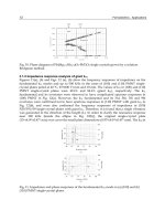
The copper/brass cellular design (Figure 1) uses brass tube
assemblies (0.15 to 0.4 mm) as the water course and convoluted
copper fins (0.08 to 0.2 mm) held together with a lead-tin solder.
The tanks and connecting pipes are usually brass (0.66 to 0.86 mm)
and again are attached to the core by a lead-tin solder. Capacity is
adjusted by varying the face area of the core to increase or decrease
the heat transfer surface area.
The aluminum tube and fin design generally uses round copper
or aluminum tubes mechanically joined to aluminum fins. U-tubes
can take the place of a conventional return tank. The inlet/outlet
tank and connecting pipes are generally plastic and clinched onto
the core with a rubber gasket. Capacity can be adjusted by varying
face area, adding coolant-side turbulators, or varying air-side sur-
face geometry for turbulence and air restriction.
The aluminum brazed tube and center design uses flat aluminum
tubes and convoluted fins or centers as the heat transfer surface.
Tanks can be either plastic and clinched onto the core or aluminum
and brazed to the core. Connecting pipes can be constructed of var-
ious materials and attached to the tanks a number of ways, including
brazing, clinching with an o-ring, fastening with a gasket, and so
forth. Capacity can be adjusted by varying face area, core depth, or
air-side surface geometry.
Receiver-Drier Assembly
The receiver-drier assembly accommodates charge fluctuations
from changes in system load (refrigerant flow and density). It accom-
modates an overcharge of refrigerant (0.25 to 0.5 kg) to compensate
for system leaks and hose effusion. The assembly houses the high-side
filter and desiccant. Several types of desiccant are used, the most com-
mon of which is spherical molecular sieves; silica gel is occasionally
used. Mechanical integrity (freedom from powdering) is important
because of the vibration to which the assembly is exposed. For this
reason, molded desiccants have not obtained wide acceptance.
Moisture retention at elevated temperatures is also important.
The rate of release with temperature increase and the reaction while
accumulating high concentration should be considered. Design tem-
peratures of at least 60°C should be used.
The receiver-drier often houses a sight glass that allows visual
inspection of the system charge level. It houses safety devices such
as fusible plugs, rupture disks, or high-pressure relief valves. High-
pressure relief valves are gaining increasing acceptance because
they do not vent the entire charge. Location of the relief devices is
Fig. 1 Typical Copper-Brass Cellular Heater Core Capacity
Surface Transportation 8.5
important. Vented refrigerant should be directed so as not to endan-
ger personnel.
Receivers are usually (though not always) mounted on or near
the condenser. They should be located so that they are ventilated by
ambient air. Pressure drops should be minimal.
Expansion Valves
Thermostatic expansion valves (TXVs) control the flow of
refrigerant through the evaporator. These are applied as shown in
Figures 4, 5, and 6. Both liquid- and gas-charged power elements are
used. Internally and externally equalized valves are used as dictated
by system design. Externally equalized valves are necessary where
high evaporator pressure drops exist. A bulbless expansion valve,
usually block-style, that senses evaporator outlet pressure without
the need for an external equalizer, is now widely used. There is a
trend toward variable compressor pumping rate expansion valves.
Orifice Tubes
An orifice tube instead of an expansion valve has come into
widespread use to control refrigerant flow through the evaporator,
primarily due to its lower cost. Components must be matched to
obtain proper performance. Even so, under some conditions liquid
refrigerant floods back to the compressor with this device. Chapter
45 of the 1998 ASHRAE Handbook—Refrigeration covers the
design of orifice tubes.
Suction Line Accumulators
A suction line accumulator is required with an orifice tube to
ensure uniform return of refrigerant and oil to the compressor to pre-
vent slugging and to cool the compressor. It also stores excess
refrigerant. A typical suction line accumulator is shown in Figure 2.
A bleed hole at the bottom of the standpipe meters oil and liquid
refrigerant back to the compressor. The filter and desiccant are con-
tained in the accumulator because no receiver-drier is used with this
system. The amount of refrigerant charge is more critical when a
suction line accumulator is used than it is with a receiver-drier.
Refrigerant Flow Control
The cycling clutch designs shown in Figures 3 and 4 are common
for both factory- and dealer-installed units. The clutch is cycled by
a thermostat that senses evaporator temperature or by a pressure
switch that senses evaporator pressure. Some dealer-installed units
use an adjustable thermostat, which controls car temperature by
controlling evaporator temperature. The thermostat also prevents
evaporator icing. Most units use a fixed thermostat or pressure
switch set to prevent evaporator icing. Temperature is then con-
trolled by blending the air with warm air coming through the heater.
Cycling the clutch sometimes causes noticeable surges as the
engine is loaded and unloaded by the compressor. This is more evi-
dent in cars with smaller engines. Reevaporation of condensate
from the evaporator during the off-cycle may cause objectionable
temperature fluctuation or odor. This system cools faster and at
lower cost than a continuously running system.
In orifice tube-accumulator systems, the clutch cycling switch
disengages at about 170 kPa and cuts in at about 310 kPa (gage).
Thus, the evaporator defrosts on each off-cycle. The flooded evap-
orator has enough thermal inertia to prevent rapid clutch cycling. It
is desirable to limit clutch cycling to a maximum of 4 cycles per
minute because heat is generated by the clutch at engagement. The
pressure switch can be used with a thermostatic expansion valve in
a dry evaporator if the pressure switch is damped to prevent rapid
cycling of the clutch.
Continuously running systems, once widely used, are rarely seen
today because they require more power and, consequently, more
fuel to operate. In a continuously running system, an evaporator
pressure regulator (EPR) keeps the evaporator pressure above the
condensate freezing level. Temperature is controlled by reheat or by
blending the air with warm air from the heater core.
The continuously running system possesses neither of the previ-
ously mentioned disadvantages of the cycling clutch system, but it
does increase the suction line pressure drop, which reduces perfor-
mance slightly at maximum load. A solenoid version of this valve,
Fig. 2 Typical Suction Line Accumulator
Fig. 3 Clutch Cycling Orifice Tube
Air-Conditioning Schematic
Fig. 4 Clutch Cycling System with Thermostatic
Expansion Valve (TXV)
Surface Transportation 8.7
has a greater sensible cooling capacity in hot, dry climates than in
humid climates.
Ambient air quality must also be considered. Frequently, intakes
are subjected to thermal contamination either from road surfaces,
condenser air recirculation, or radiator air discharge. Vehicle
motion also introduces pressure variables that affect condenser fan
performance. In addition, engine speed affects compressor capacity.
Bus air conditioners are initially performance-tested as units in
small climate-controlled test cells. Larger test cells that can hold the
whole bus are commonly used to verify as-installed performance.
Heat Load
The main parameters that must be considered in the design of a
bus air conditioning system include:
• Occupancy data (number of passengers, distance traveled, dis-
tance traveled between stops, typical permanence time)
• Dimensions and optical properties of glass
• Outside weather conditions (temperature, relative humidity, solar
radiation)
• Dimensions and thermal properties of materials in the bodies of
the bus and indoor design conditions (temperature, humidity, and
air velocity)
The heating or cooling load in a passenger bus may be estimated
by summing the following loads:
• Heat flux from solid walls (side panels, roof, floor)
• Heat flux from glass (side, front and rear windows)
• Heat flux from passengers
• Heat flux from the engine, passengers, and ventilation (difference
in enthalpy between outside and inside air)
• Heat flux from the air conditioner
The extreme loads for both summer and winter should be calcu-
lated. The cooling load is the most difficult load to handle; the
heating load is normally handled by heat recovered from the
engine. An exception is that an idling engine provides marginal
heat in very cold climates. James and He (1993) and Andre et al.
(1994) describe computational models for calculating the heat load
in vehicles, as well as for simulating the thermal behavior of the
passenger compartment.
The following conditions can be assumed for calculating the
summer heat load in an interurban vehicle similar to that shown in
Figure 7:
• Capacity of 50 passengers
• Insulation thickness of 25 to 40 mm
• Double-pane tinted windows
• Outdoor air intake of 190 L/s
• Road speed of 100 km/h
• Inside design temperatures of 27°C dry bulb and 19.5°C wet bulb,
or 11 K lower than ambient
Loads from 12 to 35 kW are calculated, depending on the outside
weather conditions and on the geographic location of the bus. The
typical distribution of the different heat loads during a summer day
at 40° North latitude is shown in Figure 8.
Inlets and Outlets
Correct positioning of external air inlets and outlets to the pas-
senger compartment is important on interurban buses that operate
mostly at a high, constant speed. Figure 9 shows the pressure coef-
ficient distribution around a typical bus. The main features, result-
ing from the analysis of the figure are
• On the front surface, most of the pressure is positive, with the
stagnation point located at 1/3 of the height.
• At the frontal leading edge, the pressure is strongly negative.
Fig. 7 Distribution of Heat Load (Summer)
0
2
4
6
8
10
12
Glass Occupants Ventilation
w/Outside Air
Interior
Bodies
Walls Engine
HEAT LOAD, kW
Convec.
+
Conduc.
Radiation
Latent
Heat
Sensible
Heat
Latent
Heat
Sensible
Heat
Fig. 8 Main Heat Fluxes in a Bus
Cp = 1
0
Cp = 1
A
B
C
D
E
Fig. 9 Pressure Distribution Around a Moving Bus
Surface Transportation 8.9
or alternating current (ac) power supplied from an overhead cat-
enary or from a dc-supplied third rail system. On such cars, the
air conditioning may operate on ac or dc power. Self-propelled
diesel-driven vehicles still operate in a few areas that use on-
board generated power for the air conditioners.
Subway and elevated rapid-transit cars usually operate on a
third rail dc power supply. The car air conditioning operates on the
normal dc supply voltage or on three-phase ac supply from an alter-
nator or inverter mounted under the car. Split air-conditioning sys-
tems are common, with evaporators in the interior ceiling area and
underfloor-mounted condensing sections.
Streetcars, light rail vehicles, and downtown people movers
usually run on the city ac or dc power supply and have air-condi-
tioning equipment similar to rapid transit cars. Roof-mounted
packages are used more often than under car or split systems.
This is partly because of the lack of undercar space availability
and in cases, where a sufficient clearance envelope will allow,
the roof mounted location offers the most convenient location for
add-on systems and for modifying rail vehicles designed without
HVAC.
Equipment Selection
The source and type of power dictate the type of air conditioning
installed on a passenger railcar; weight, the type of vehicle, and the
service parameters of the vehicle to which the system is applied are
other major concerns. Thus, ac-powered, semi-hermetic reciprocat-
ing, vane, or scroll hermetic compressors, which are lighter than
open machines with dc motor drives, are a common choice. How-
ever, each car design must be examined in this respect because dc/ac
inverters may increase not only the total weight, but also the total
power draw, due to conversion losses.
Other concerns in equipment selection include the space re-
quired, location, accessibility, reliability, and maintainability. Inte-
rior and exterior equipment noise levels must be considered both
during the early stages of design and later, when the equipment is
coordinated with the car builder’s ductwork and grilles.
Design Limitations
Space underneath and inside a railroad car is at a premium, espe-
cially on self-propelled light rail vehicles and rapid transit and com-
muter cars; this generally rules out unitary interior or underfloor-
mounted systems. Components are usually built to fit the configu-
ration of the available space. Overall car height, roof profile, ceiling
cavity, and undercar clearance restrictions determine the shape and
size of equipment.
Because a mainline passenger railcar must operate in various
parts of the country, the air conditioning must be designed to handle
the national seasonal extreme design days. Commuter cars and
rapid transit cars operate in a small geographical area, so only the
local design temperatures and humidities need be considered.
Dirt and corrosion constitute an important design factor, espe-
cially if the equipment is beneath the car floor, where it is subject
to extremes of weather and severe dirt conditions. For this rea-
son, corrosion-resistant materials and coatings must be selected.
Aluminum has not proved durable in exterior exposed applica-
tions; the sandblasting effect tends to degrade any surface treat-
ment on it. Because dirt pickup cannot be avoided, the equipment
must be designed for quick and easy cleaning; access doors are
provided and evaporator and condenser fin spacing is usually
limited to 2.5 to 3 mm. Closer spacing causes more rapid dirt
buildup and higher cleaning costs. Dirt and severe environmental
conditions must also be considered in selecting motors and con-
trols.
Railroad HVAC equipment requires more maintenance and ser-
vicing than stationary units. A passenger railcar, having sealed win-
dows and a well-insulated structure, becomes almost unusable if
the air conditioning fails. The equipment therefore has many addi-
tional components to permit quick diagnosis and correction of a
failure. Motors, compressors, control compartments, diagnostic test
ports and other maintenance points must be easily accessible for
inspection or repair. However, changes in maintenance strategies
and environmental regulations have caused some users to move
away from fully on-car serviceable air conditioners, and toward
modular, self-contained units with hermetically sealed refrigerant
systems. These units are designed for rapid removal and replace-
ment and off-car repair in a dedicated air-conditioning service area.
Microprocessor-based controls are designed to identify, log, and
indicate system faults in a manner that facilitates expeditious diag-
nosis and repair.
Security of the air-conditioning equipment attachment to the
vehicle must be considered, especially on equipment located
beneath the car. Vibration isolators and supports should be designed
to safely retain the equipment on the vehicle, even if the vibration
isolators or fasteners fail completely. A piece of equipment that dan-
gles or drops off could cause a train derailment. All belt drives and
other revolving items must be safety guarded. High-voltage controls
and equipment must be labeled by approved warning signs. Pres-
sure vessels and coils must meet ASME test specifications for pro-
tection of the passengers and maintenance personnel. Materials
selection criteria include low flammability, low toxicity, and low
smoke emission.
The design, location, and installation of air-cooled condenser
sections must allow for considerable discharge air recirculation
and/or temporary extreme inlet air temperatures from adjacent
equipment that may occur at passenger loading platforms or in tun-
nels. To prevent a total system shutdown due to high discharge
pressure, a capacity reduction control device is typically used to
reduce the cooling capacity, thus temporarily reducing discharge
pressure.
Interior Comfort
Air-conditioning and heating comfort and ventilation parame-
ters may be selected in accordance with ASHRAE Standards 55
and 62. The duration of exposure and the effect of prior passenger
activity should also be considered. For example, a person running
for a ride and/or waiting in a hot or cold climate prior to boarding
for a 10 minute ride in clothing fit for outside is not a typical build-
ing occupant. Jones et al. (1994) evaluated the heat load imposed
by people under transient weather and activity conditions as
opposed to steady state metabolic rates traditionally used. An appli-
cation program TRANMOD was developed that allows a designer
to predict the thermal loads imposed by passengers (Jones and He
1993).
Door openings, ventilation air sources (ambient contamination),
and loading profiles need to be considered when locating inlets and
calculating the amount of makeup air. Evaporator sectional stag-
ing, variable compressor and evaporator fan speed control, and/or
compressor cylinder unloading, coupled with electric reheat, are
used to provide part-load humidity control. In winter, humidity
control is usually not provided.
The dominant summer cooling load is due to passengers, fol-
lowed by ventilation, car body transmission, solar gain, and inter-
nal heat. Heating loads are due to car body losses and ventilation.
The heating load calculation does not credit heat from passengers
and internal sources. Comfortable internal conditions in ventilated
non-air-conditioned cars can be maintained only when ambient
conditions permit. Interior conditions are difficult to maintain
because the passenger and solar loads in mass transit cars vary
continuously.
Air conditioners in North American cars are selected to maintain
temperatures of 23 to 24.5°C, with a maximum relative humidity of
55 to 60%. In Europe and elsewhere, the conditions are usually set
at a dry-bulb temperature approximately 5 K below ambient, with a
Surface Transportation 8.11
vehicle and fitted to its ceiling contours. The condensing units must
also be arranged to fit in the limited space available and still ensure
good airflow across the condenser coil. R-22 is used in almost all of
these units.
Heating
Where heating must be provided, electric resistance heaters that
operate on the guideway power supply are installed at the evapora-
tor unit discharge. One or two stages of heat control are used,
depending on the size of the heaters.
Controls
A solid-state control is usually used to maintain interior condi-
tions. The cooling set point is typically between 23 and 24°C. For
heating, the set point is 20°C or lower. Some controls provide
humidity control by using the electric heat. Between the cooling and
heating set points, blowers continue to operate on a ventilation
cycle. Often, two-speed blower motors are used, switching to low
speed for the heating cycle. Some controls have internal diagnostic
capability; they are able to signal the operations center when a cool-
ing or heating malfunction occurs.
Fresh Air
With overhead air-handling equipment, fresh air is introduced
into the return airstream at the evaporator entrance. Fresh air is usu-
ally taken from a grilled or louvered opening in the end or side of the
car and, depending on the configuration of components, filtered
separately or directed so that the return air filter can handle both air-
streams. For undercar systems, a similar procedure is used, except
the air is introduced into the system through an intake in the under-
car enclosure. In some cases, a separate fan is used to induce fresh
air into the system.
The amount of mechanical outdoor air ventilation is usually
expressed as L/s per passenger on a full load continuous basis. Pas-
senger loading is not continuous at full load in this application,
with the net result that more outside air is provided than indicated.
The passengers may load and unload in groups, which causes addi-
tional air exchange with the outside. Frequent opening of doors,
sometimes on both sides at once, allows additional natural ventila-
tion. The effective outside air ventilation per passenger is a sum-
mation of all these factors. Some vehicles currently in service have
no mechanical outside air supply. Others have up to 5 L/s per pas-
senger. Lower values of mechanical ventilation, typically 2.5 L/s
or less per passenger, are associated with travel times of less than
2 min and large passenger turnover. Longer rides justify higher
rates of mechanical ventilation.
Air Distribution
With overhead equipment, air is distributed through linear ceiling
diffusers that are often constructed as a part of the overhead lighting
fixtures. Undercar equipment usually makes use of the void spaces in
the sidewalls and below fixed seating. In all cases, the spaces used for
air supply must be adequately insulated to prevent condensation on
surfaces and, in the case of voids below seating, to avoid cold seating
surfaces. The supply-air discharge from undercar systems is typically
through a windowsill diffuser. Recirculation air from overhead equip-
ment flows through ceiling-mounted grilles. For undercar systems,
return air grilles are usually found in the door wells or beneath seats.
Because of the small size of the vehicle and its low ceilings,
extreme care must be taken to design the air supply so that it does
not blow directly on passengers’ heads or shoulders. High rates of
diffusion are needed, and diffuser placement and arrangement
should cause the discharge to hug the ceiling and walls of the car.
Total air quantity and discharge temperature must be carefully bal-
anced to minimize cold drafts and air currents.
REFERENCES
Andre, J.C.S., E.Z.E. Conceição, M.C.G. Silva, and D.X. Viegas. 1994. Inte-
gral simulation of air conditioning in passenger buses. Fourth Interna-
tional Conference on Air Distribution in Rooms (ROOMVENT 94).
ASHRAE. 1989. Ventilation for acceptable indoor air quality. ANSI/ ASH-
RAE Standard 62-1989.
ASHRAE. 1992. Thermal environmental conditions for human occupancy.
ANSI/ASHRAE Standard 55-1992.
Giles, G.R., R.G. Hunt, and G.F. Stevenson. 1997. Air as a refrigerant for the
21st century. Proceedings ASHRAE/NIST Refrigerants Conference,
Refrigerants for the 21st Century.
Jones, B.W., Q. He, J.M. Sipes, and E.A. McCullough. 1994. The transient
nature of thermal loads generated by people. ASHRAE Transactions
100(2):432-38.
Jones, B.W. and Q. He. 1993. User manual. Transient human heat transfer
model (includes application TRANMOD). Institute of Environmental
Research, Kansas State University, Manhattan.
SAE. 1994. Safety and containment of refrigerant for mechanical vapor
compression systems used for mobile air-conditioning systems. Recom-
mended Practice J 639 1994. SAE International, Warrendale, PA.
BIBLIOGRAPHY
Conceição, E.Z.E., M.C.G. Silva, and D.X. Viegas. 1997. Airflow around a
passenger seated in bus. International Journal of HVAC&R Research
3(4):311-23.
Conceição, E.Z.E., M.C.G. Silva, and D.X. Viegas. 1997. Air quality inside
the passenger compartment of a bus. Journal of Exposure Analysis &
Environmental Epidemiology 7:521-34.
Silva, M.C.G. and D.X. Viegas. 1994. External flow field around an intercity
bus. Second International Conference on Experimental Fluid Mechanics.
CHAPTER 9
AIRCRAFT
Regulations 9.1
Design Conditions 9.2
System Description 9.4
Typical Flight 9.7
Air Quality 9.9
NVIRONMENTAL control system (ECS) is a generic term
Eused in the aircraft industry for the systems and equipment
associated with the ventilation, heating, cooling, humidity/contam-
ination control, and pressurization in the occupied compartments,
cargo compartments, and electronic equipment bays. The term ECS
often encompasses other functions such as windshield defog, airfoil
anti-ice, oxygen systems, and other pneumatic demands. The regu-
latory or design requirements of these related functions are not cov-
ered in this chapter.
Environmental control systems of various types and complex-
ity are used in military and civil aircraft, helicopter, and space-
craft applications. This chapter applies to commercial transport
aircraft that predominately use air-cycle air conditioning for the
ECS.
Commercial users categorize their ECS equipment in accor-
dance with the Air Transport Association of America Specifica-
tion No. 100, Specification for Manufacturers Technical Data.
The following ATAA 100 chapters define ECS functions and
components:
• Chapter 21, Air Conditioning, includes heating, cooling, mois-
ture/contaminant control, temperature control, distribution, and
cabin pressure control. Common system names are the air-condi-
tioning system (ACS) and the cabin pressure control system
(CPCS).
• Chapter 30, Ice and Rain Protection, includes airfoil ice protec-
tion; engine cowl ice protection; and windshield ice, frost, or rain
protection.
• Chapter 35, Oxygen, includes components that store, regulate,
and deliver oxygen to the passengers and crew.
• Chapter 36, Pneumatic, covers ducts and components that
deliver compressed air (bleed air) from a power source (main
engine or auxiliary power unit) to connecting points for the using
systems (Chapters 21, 30, and Chapter 80, Starting). The pneu-
matic system is also commonly called the engine bleed air system
(EBAS).
REGULATIONS
The Federal Aviation Administration (FAA) regulates the design
of transport category aircraft for operation in the United States
under Federal Aviation Regulation (FAR) Part 25. ECS equipment
and systems must meet these requirements, which are primarily
related to health and safety of the occupants. Certification and oper-
ation of these aircraft in the U.S. is regulated by the FAA in FAR
Part 121. Similar regulations are applied to European nations by the
European Joint Aviation Authorities (JAA), which represents the
combined requirements of the airworthiness authorities of the par-
ticipating nations; the equivalent design regulation is JAR Part 25.
Operating rules based on FAA or JAA regulations are applied indi-
vidually by the nation of registry. Regulatory agencies may impose
special conditions on the design, and compliance is mandatory.
Several FAR and JAR Part 25 paragraphs apply directly to trans-
port category aircraft ECSs; those most germane to the ECS design
requirements are as follows:
FAR/JAR 25.831 Ventilation
FAR 25.832 Cabin ozone concentration
FAR/JAR 25.841 Pressurized cabins
FAR/JAR 25.1309 Equipment, systems, and installations
FAR/JAR 25.1438 Pressurization and pneumatic systems
FAR/JAR 25.1461 Equipment containing high energy rotors
These regulatory requirements are summarized in the following
sections; however, the applicable FAR and JAR paragraphs, amend-
ments and advisory circulars should be consulted for the latest revi-
sions and full extent of the rules.
Ventilation
FAR/JAR Paragraph 25.831
• Each passenger and crew compartment must be ventilated.
• Each crew member must have enough fresh air to perform their
duties without undue fatigue or discomfort (minimum of 4.7 L/s).
• Crew and passenger compartment air must be free from hazard-
ous concentration of gases and vapors:
- Carbon monoxide limit is 1 part in 20 000 parts of air
- Carbon dioxide limit is 3% by volume, sea level equivalent (An
FAA amendment reduces the carbon dioxide limit to 0.5%)
- Conditions must be met after reasonably probable failures
• Smoke evacuation from the cockpit must be readily accomplished
without depressurization.
• The occupants of the flight deck, crew rest area, and other areas
must be able to control the temperature and quantity of ventilating
air to their compartments independently.
FAR Amendment No. 25-87:
• Under normal operating conditions and in the event of any prob-
able failure, the ventilation system must be designed to provide
each occupant with an airflow containing at least 0.25 kg of fresh
air per minute (or about 5 L/s at 2400 m).
• The maximum exposure an any given temperature is specified as
a function of the temperature exposure.
JAR ACJ (Advisory Circular-Joint) 25.831:
• The supply of fresh air in the event of loss of one source, should
not be less than 3 g/s per person for any period exceeding 5 min.
However, reductions below this flow rate may be accepted pro-
vided that the compartment environment can be maintained at a
level that is not hazardous to the occupant.
• Where the air supply is supplemented by a recirculating system, it
should be possible to stop the recirculating system.
Cabin Ozone Concentration
FAR 25.832 specifies the cabin ozone concentration during
flight must be shown not to exceed:
The preparation of this chapter is assigned to TC 9.3, Transportation Air
Conditioning.
Aircraft 9.3
and repressurization during descent, while accounting for certain
failure conditions. The ECS also includes provisions to dehumidify
the cabin supply during cooling operations.
Load Determination. The steady-state cooling and heating
loads for a particular aircraft model are determined by a heat trans-
fer study of the several elements that comprise the air-conditioning
load. The heat transfer involves the following factors:
• Convection between the boundary layer and the outer aircraft skin
• Radiation between the outer aircraft skin and the external
environment
• Solar radiation through transparent areas
• Conduction through cabin walls and the aircraft structure
• Convection between the interior cabin surface and the cabin air
• Convection between the cabin air and occupants or equipment
• Convection and radiation from internal sources of heat such as
electrical equipment
The heat transfer analysis should include all possible flow paths
through the complex aircraft structure. Air film coefficients vary
with altitude and should be considered. During flight, the increase in
air temperature and pressure due to ram effects is appreciable and
may be calculated from the following equations:
wherewhere
F
r
= recovery factor, dimensionless
∆
t
r
= increase in temperature due to ram effect, K
M = Mach number, dimensionless
T
a
= absolute static temperature of ambient air, K
∆
p
r
= increase in pressure due to ram effect, kPa
p
a
= absolute static pressure of ambient air, kPa
The average increase in aircraft skin temperature for subsonic flight
is generally based on a recovery factor F
r
of 0.9.
Ground and flight requirements may be quite different. For an
aircraft sitting on the ground in bright sunlight, surfaces that have
high absorptivity and are perpendicular to the sun’s rays may have
much higher temperatures than ambient. This skin temperature is
reduced considerably if a breeze blows across the aircraft. Other
considerations for ground operations include cool-down or warm-
up requirements, and the time that doors are open for passenger and
galley servicing.
Cooling. The sizing criteria for the air conditioning is usually
ground operation on a hot, humid day with the aircraft fully
loaded and the doors closed. A second consideration is cool-down
of a empty, heat-soaked aircraft prior to passenger loading; a cool-
down time of less than 30 minutes is usually specified. A cabin
-70
-65
-60
-55
-50
-45
-40
-35
-30
-25
-20
-15
-10
-5
0
5
10
15
20
25
30
35
40
45
50
55
-1500 0 1500 3000 4500 6000 7500 9000
AMBIENT TEMPERATURE, °C
ALTITUDE, m
MAXIMUM
HOT DAY
HOT DAY
ISA (International
Standard Atmosphere)
COLD DAY
Fig. 1 Typical Ambient Temperature Profiles
Fig. 2 Design Moisture for Equipment Performance
0
10
20
30
40
50
60
70
80
90
100
110
0123456789101112131415
AMBIENT PRESSURE, kPa
ALTITUDE, km
Fig. 3 Variation of Ambient Pressure with Altitude
∆t
r
0.2M
2
T
a
F
r
=
∆p
r
10.2M
2
+()
3.5
p
a
p
a
–=
Aircraft 9.5
extending along the wing leading edge. Similar arrangements are
used for anti-icing the engine cowl and tail section.
Air Conditioning
Air-cycle refrigeration is the predominant means of air condi-
tioning for commercial and military aircraft. The reverse-Brayton
cycle or Brayton refrigeration cycle is used as opposed to the Bray-
ton power cycle that is used in gas turbine engines. The difference
between the two cycles is that in the power cycle fuel in a combus-
tion chamber adds heat, and in the refrigeration cycle a ram-air heat
exchanger removes heat. The familiar Rankine vapor cycle, which
is used in building and automotive air conditioning and in domestic
and commercial refrigeration, has limited use for aircraft air condi-
tioning. The Rankine cycle is used mostly in unpressurized helicop-
ters and general aviation applications.
In an air cycle, compression of the ambient air by the gas tur-
bine engine compressor provides the power input. The heat of
compression is removed in a heat exchanger using ambient air as
the heat sink. This cooled air is refrigerated by expansion across a
turbine powered by the compressed bleed air. The turbine energy
resulting from the isentropic expansion is absorbed by a second
rotor, which is either a ram air fan, bleed air compressor, or both.
This assembly is called an air-cycle machine (ACM). Moisture
condensed during the refrigeration process is removed by a water
separator.
The compartment supply temperature is controlled by mixing
hot bleed air with the refrigerated air to satisfy the range of heating
and cooling. Other more sophisticated means of temperature control
are often used; these include ram air modulation, various bypass
schemes in the air-conditioning pack, and downstream controls that
add heat for individual zone temperature control.
The bleed airflow is controlled by a flow control or pressure
regulating valve at the inlet of the air-conditioning pack. This valve
controls bleed air used to minimize engine bleed penalties while
satisfying the aircraft outside air ventilation requirements.
Fig. 5 Cabin Airflow Patterns
(Hunt et al. 1995)
Fig. 6 Typical Engine Bleed Air System Schematic
(Hunt et al. 1995)
9.6 1999 ASHRAE Applications Handbook (SI)
Most aircraft use two or three air-cycle packs operating in paral-
lel to compensate for failures during flight and to allow the aircraft
to be dispatched with certain failures. However, many business and
commuter aircraft use a single-pack air conditioner; high-altitude
aircraft that have single pack also have emergency pressurization
equipment that uses precooled bleed air.
The most common types of air-conditioning cycles in use on
commercial transport aircraft are shown in Figure 7. All equipment
in common use on commercial and military aircraft are open loop,
although many commercial aircraft systems include various means
of recirculating cabin air to minimize engine bleed air use without
sacrificing cabin comfort. The basic differences between the sys-
tems are the type of air-cycle machine used and its means of water
separation.
The most common air-cycle machines in use are the bootstrap
ACM consisting of a turbine and compressor; the three-wheel ACM
consisting of a turbine, compressor, and fan; and the four wheel
ACM consisting of a two turbines, a compressor, and a fan. The
bootstrap ACM is most commonly used for military applications,
although many older commercial aircraft models use the bootstrap
cycle. The three-wheel ACM (simple bootstrap cycle) is used on
most of the newer commercial aircraft, including commuter aircraft
and business aircraft. The four-wheel ACM (condensing cycle) was
first applied in 777 aircraft.
Low-pressure water separation and high-pressure water separa-
tion are used. A low-pressure water separator, located down-
stream from the cooling turbine, has a coalescer cloth that
agglomerates fine water particles entrained in the turbine discharge
air into droplets. The droplets are collected, drained, and sprayed
into the ram airstream using a bleed air powered ejector; this process
increases pack cooling capacity by depressing the ram-air heat-sink
temperature.
The high-pressure water separator condenses and removes
moisture at high pressure upstream of the cooling turbine. A heat
exchanger uses turbine discharge air to cool the high-pressure air
sufficiently to condense most of the moisture present in the bleed air
supply. The moisture is collected and sprayed into the ram air-
stream.
In the condensing cycle one turbine removes the high-pressure
water and the second turbine does the final expansion to subfreezing
temperature air that is to be mixed with filtered, recirculated cabin
air. Separating these functions recovers the heat of condensation,
which results in a higher cycle efficiency. It also eliminates con-
denser freezing problems because the condensing heat exchanger is
operated above freezing conditions.
The air-conditioning packs are located in unpressurized areas of
the aircraft to minimize structural requirements of the ram air circuit
that provides the necessary heat sink for the air-conditioning cycle.
This location also provides protection against cabin depressuriza-
tion in the event of a bleed or ram air duct rupture. The most com-
mon areas for the air-conditioning packs are the underwing/wheel
well area and the tail cone area aft of the rear pressure bulkhead.
Other areas include the areas adjacent to the nose wheel and over-
wing fairing. The temperature control components and recirculating
fans are located throughout the distribution system in the pressur-
ized compartments. The electronic pack and zone temperature con-
trollers are located in the E/E bay. The air-conditioning control
panel is located in the flight deck. A schematic diagram of a typical
air-conditioning system is shown in Figure 8.
Cabin Pressure Control
Cabin pressure is controlled by modulating the airflow dis-
charged from the pressurized cabin through one or more cabin out-
flow valves. The cabin pressure control includes the outflow valves,
controller, selector panel, and redundant positive pressure relief
valves. Provisions for negative pressure relief are incorporated in
the relief valves and/or included in the aircraft structure (door). The
system controls the cabin ascent and descent rates to acceptable
comfort levels, and maintains cabin pressure altitude in accordance
with cabin-to-ambient differential pressure schedules. Modern con-
trols usually set landing field altitude if not available from the flight
management system (FMS), and monitor aircraft flight via the FMS
and the air data computer (ADC) to minimize the cabin pressure
altitude and rate of change.
The cabin pressure modulating valves and safety valves (positive
pressure relief valves) are located either on the aircraft skin in the
case of large commercial aircraft, or on the fuselage pressure bulk-
head in the case of commuter, business and military aircraft. Locat-
ing the outflow valves on the aircraft skin precludes the handling of
large airflows in the unpressurized tailcone or nose areas and pro-
vides some thrust recovery; however, these double gate valves are
more complex than the butterfly valves or poppet-type valves used
for bulkhead installations. The safety valves are poppet-type valves
for either installation. Most commercial aircraft have electronic
controllers located in the E/E bay. The cabin pressure selector panel
is located in the flight deck.
Fig. 7 Air-Conditioning Air-Cycle Configurations
9.8 1999 ASHRAE Applications Handbook (SI)
packs. The ozone further dissociates when contacting airplane
ducts, interior surfaces, and the airplane recirculation system. The
ozone converter dissociates ozone to oxygen molecules by the cat-
alyzing action of a noble catalyst such as palladium. A new con-
verter dissociates approximately 95% of the ozone entering the
converter to oxygen. It has a useful life of about 12,000 flight hours.
As the air leaves the ozone converter, it is still at 200°C and a
pressure of 200 kPa. Assuming a worst case when the converter is
approaching the end of its useful life with an ozone conversion effi-
ciency of 60%, the ozone concentration leaving the converter is
about 0.25 ppm SLE. This air goes through the air-conditioning
packs and enters the cabin. The ozone concentration in the cabin is
about 0.09 ppm. As mentioned in the section on Regulations, the
FAA sets a three-hour time-weighted average ozone concentration
limit in the cabin of 0.1 ppm and a peak ozone concentration limit
of 0.25 ppm.
Air Conditioning and Temperature Control
The air next enters the air-conditioning packs. The air-condition-
ing pack provides essentially dry, sterile, and dust free conditioned
air to the airplane cabin at the proper temperature, flow rate, and pres-
sure to satisfy pressurization and temperature control requirements.
For most aircraft, this is approximately 2.5 L/s per passenger. To
ensure redundancy, two air-conditioning packs (two are typical,
some aircraft have more) provide a total of about 5 L/s of conditioned
air per passenger. An equal quantity of filtered, recirculated air is
mixed with the air from the air-conditioning packs for a total of
approximately 10 L/s per passenger. This quantity of supply air
results in a complete cabin air exchange about every 2.5 min, or about
25 air changes per hour. The high air exchange rate is necessary to
control temperature gradients, prevent stagnant cold areas, maintain
air quality, and dissipate smoke and odors in the cabin. Temperature
control is the predominant driver of outside airflow requirements.
The automatic control for the air-conditioning packs constantly
monitors airplane flight parameters, the flight crew’s selection for
the temperature zones, the cabin zone temperature, and the mixed
distribution air temperature. The control automatically adjusts the
various valves for a comfortable environment under normal condi-
tions. The pilot’s controls are located on the overhead panel in the
flight deck along with the bleed system controls. Normally, pilots
are required only to periodically monitor the compartment temper-
atures from the overhead panel. Temperatures can be adjusted based
on flight attendant reports of passengers being too hot or too cold.
Various selections are available to the pilots to accommodate abnor-
mal operational situations.
Air Recirculation
The air has now been cooled and leaves the air-conditioning
packs. It leaves the packs at 15°C and 80 kPa. The relative humidity
is less than 5% and ozone concentration is less than 0.25 ppm. The
carbon dioxide concentration remains unchanged from that of the
outside air at about 350 ppm. As this air enters a mixing chamber, it
is combined with an equal quantity of filtered recirculated air.
The recirculated air entering the mix manifold is essentially ster-
ile. Over 99.9% of the bacteria and viruses produced by the passen-
gers are removed by HEPA filters, which are used on most modern
aircraft. The filters cannot be bypassed and become more efficient
with increased service life. They do, however, require replacement
at periodic maintenance intervals. Gases, which are not removed by
the filters, are diluted to low levels with outside air at a high
exchange rate of about 12.5 times per hour.
Air Distribution
The air flows from the mix manifold into duct risers dedicated to
each seating zone. The risers direct the air from below the floor to the
overhead cabin ventilation system. Trim air (hot bleed air from the
pneumatic manifold) is added in the risers to increase the air temper-
ature, if needed. The supply air temperature per seating zone can
vary due to differences in seating densities between seating zones.
The overhead air distribution network runs the length of the
cabin. The air is dust free and sterile with a relative humidity of 10%
to 20%. The temperature is 18 to 29°C, depending upon the seating
zone the air is being supplied to, and the carbon dioxide concentra-
tion is about 1050 ppm. The carbon dioxide is generated by passen-
ger respiration.
Due to the large quantity of air entering the relatively small vol-
ume of the cabin, as compared to a building, control of the airflow
patterns is required to give comfort without draftiness. Air enters
the passenger cabin from overhead distribution outlets that run the
length of the cabin. These outlets create circular airflow patterns in
the cabin (Figure 5). Air leaves the outlets at a velocity of more than
2.5 m/s, becomes entrained with cabin air, and maintains sufficient
momentum to sweep the cabin walls and floor and to wash out any
cold pockets of air in the cabin. The air direction is oriented to avoid
exposed portions of a seated passenger, such as the arms, hand, face,
neck, and legs; yet it is of sufficient velocity to avoid the sensation
of stagnant air. This requires seated passenger impingement veloc-
ities between 0.1 and 0.35 m/s.
The air volume circulates in the cabin while continuously mixing
with cabin air for 2 to 3 min before it enters the return air grilles that
are located in the sidewalls near the floor and run the length of the
cabin along both sides. While this air is in the cabin, about 0.33% of
the oxygen is consumed by human metabolism. The oxygen is
replaced by an equal quantity of carbon dioxide from passenger res-
piration. In addition, the return air entrains microorganisms or other
contaminants from passengers or the cabin itself. Approximately
one-half of the return air is exhausted overboard and the other half
recirculated to sterile conditions through HEPA filters.
In the aft section, exhaust air is extracted by the cabin pressure
outflow valve and exhausted overboard. In the forward section, it is
continuously extracted from below the floor by recirculation fans
filtered, and then mixed with the outside air being supplied by the
air-conditioning packs.
The cabin ventilation is balanced so that air supplied at one seat
row leaves at approximately the same seat row. This minimizes
airflow in the fore and aft directions, to minimize the spread of
passenger-generated contaminants.
100
150
200
250
300
CLIMB CRUISE CRUISE DESCENT
TEMPERATURE, °C
10 700 m 12 200 m
Fig. 9 Typical Air Temperature Supplied to Bleed System
During Flight
(Adapted from Hunt et al. 1995)
9.10 1999 ASHRAE Applications Handbook (SI)
and larger than the most penetrating particle size (MPPS). For an
airplane filter, the MPPS is about 0.1 to 0.2 µm.
The efficiency of the filter to remove 0.003 µm particles from the
air is in excess of 99.9+%. Most bacteria (99%) are larger than
1 µm. Viruses are approximately 0.003 to 0.05 µm in size. Test
results in a DOT study conducted on 92 randomly selected flights
showed that bacteria and fungi levels measured in the airplane cabin
are similar to or lower than those found in the home. These low
microbial contaminant levels are due to the large quantity of outside
airflow and high filtration of the recirculation system.
Volatile Organic Compounds
Volatile organic compounds (VOCs) can be emitted by material
used in furnishings, pesticides, disinfectants, cleaning fluids, and
food and beverages. In-flight air quality testing on revenue flights
sponsored by The Boeing Company and the Air Transport Associ-
ation of America (ATAA 1994) detected trace quantities of VOCs,
which were considered well below levels that could result in
adverse health effects.
Carbon Dioxide
Carbon dioxide is the product of normal human metabolism,
which is the predominant source in aircraft cabins. The CO
2
con-
centration in the cabin varies with outside air rate, the number of
people present, and their individual rates of CO
2
production that
vary with activity and (to a smaller degree) with diet and health.
CO
2
has been widely used as an indicator of indoor air quality, typ-
ically serving the function of a surrogate. Per a DOT-sponsored
study, measured cabin CO
2
values of 92 randomly selected smoking
and nonsmoking flights average 1500 ppm.
The Environmental Exposure Limit adopted by the American
Conference of Governmental Industrial Hygienists (ACGIH) is
5000 ppm as the time-weighted average (TWA) limit for CO
2
; this
value corresponds to a fresh air ventilation rate of 1.1 L/s per per-
son. The TWA is the concentration, for a normal 8 h workday and a
40 hour workweek, to which nearly all workers can be repeatedly
exposed, day after day, without adverse effects. As mentioned in the
Regulations section under Ventilation, an FAA amendment also
limits CO
2
to 5000 ppm (0.5%). Aircraft cabin CO
2
concentrations
are below this limit.
ASHRAE Standard 62, which does not apply to aircraft per se,
states, “Comfort (odor) criteria are likely to be satisfied if the ven-
tilation rate is set so that 1000 ppm CO
2
is not exceeded.” It further
states, “This level is not considered a health risk but is a surrogate
for human comfort (odor).” An interpretation of this standard noted
that 1000 ppm CO
2
is not a requirement of the standard, but it can
be considered a target concentration level.
Humidity
The relative humidity in airplanes tested in a DOT-sponsored
study ranged from approximately 5% to 35% with an average of
15% to 20%. The humidity is made up mainly of moisture from pas-
sengers and will increase with more passengers and decrease with
increased outside airflow. A major benefit of filtered, recirculated
air supplied to the passenger cabin is an increase in cabin humidity
compared to airplanes with only outside supply air.
After three or four hours of exposure to relative humidity in the
5 to 10% range, some passengers may experience such discomfort
as dryness of the eyes, nose, and throat. However, no serious
adverse health effects of low relative humidity on the flying popu-
lation have been documented.
Cabin Pressure/Oxygen
At a normal airplane cruise altitude, aircraft cabins are pres-
surized to a maximum cabin altitude of 2400 m (to compress
the ambient air to a form that is physiologically acceptable). A
DOT-sponsored National Academy of Sciences study concluded
that current pressurization criteria and regulations are generally
adequate to protect the traveling public. The Academy also noted
that the normal maximum rates of change of cabin pressure
(approximately 150 m/min in increasing altitude and 90 m/min in
decreasing altitude) are such that they do not pose a problem for
the typical passenger.
However, pressurization of the cabin to equivalent altitudes of up
to 2400 m, as well as changes in the normal rates of pressure during
climb and descent, may create discomfort for some people such as
those suffering from upper respiratory or sinus infections, obstruc-
tive pulmonary diseases, anemias, or certain cardiovascular condi-
tions. In those cases, supplemental oxygen may be recommended.
Children and infants sometimes experience discomfort or pain
because of pressure changes during climb and descent. Injury to the
middle ear has occurred to susceptible people, but is rare.
Some articles and reports state that substandard conditions exist
in airplane cabins due to a lack of oxygen. Some reports suggest that
this condition is exacerbated by reduced fresh air ventilation rates or
through the use of recirculated air. These arguments imply that the
oxygen content of cabin air is depleted through the consumption by
occupants. Humans at rest breathe at a rate of approximately
150 mL/s while consuming oxygen at a rate of 7 mL/s. The percent
oxygen makeup of the supply air remains at approximately 21% at
cruise altitude. A person receiving 5 L/s of outside air and 5 L/s of
recirculation air would therefore receive approximately 2.1 L/s of
oxygen. Consequently, the content of oxygen in cabin air is little
affected by breathing as it is replaced in sufficient quantities com-
pared to the human consumption rate.
Although the percentage of oxygen in cabin air remains virtually
unchanged (21%) at all normal flight altitudes, the partial pressure
of oxygen decreases with increasing altitude, which decreases the
amount of oxygen held by the blood’s hemoglobin. The increase in
cabin altitude may cause low grade hypoxia (reduced tissue oxygen
levels) to some people. Low grade hypoxia in combination with
other stresses is the main cause of passenger fainting and fatigue.
However, the National Academy of Sciences concluded that pres-
surization of the cabin to an equivalent altitude of 1500 to 2400 m
is physiologically safe—no supplemental oxygen is needed to
maintain sufficient arterial oxygen saturation.
REFERENCES
ATAA. Specification for manufacturers technical data. Specification No.
100. Air Transport Association of America, Washington, DC.
ATAA. 1994. Airline cabin air quality study. Air Transport Association of
America, Washington, DC.
ASHRAE. 1991. Air quality, ventilation, temperature and humidity in air-
craft. ASHRAE Journal (4).
ASHRAE 1981. Ventilation for acceptable indoor air quality. Standard 62-
1981.
ASHRAE 1989. Ventilation for acceptable indoor air quality. ANSI/ASH-
RAE Standard 62-1989.
DOT. 1989. Airliner cabin environment: Contaminant measurements, health
risks, and mitigation options. U.S. Department of Transportation, Wash-
ington, DC.
FAA. Airworthiness standards: Transport category airplanes. Federal Avia-
tion Regulations, Part 25.
FAA. Certification and operations: Domestic, flag and supplemental air car-
riers and commercial operators of large aircraft. Federal Aviation Regu-
lations, Part 121.
Hunt, E.H. and D.R. Space. 1995. The airplane cabin environment: Issues
pertaining to flight attendant comfort. The Boeing Company, Seattle.
Hunt, E.H., D.H. Reid, D.R. Space, and F.E. Tilton. 1995. Commercial air-
liner environmental control system: Engineering aspects of cabin air
quality. Presented at the Aerospace Medical Association annual meeting,
Anaheim, CA.
JAA. Joint airworthiness requirements: Part 25: Large aeroplanes. Airwor-
thiness Authorities Steering Committee. Publisher: Civil Aviation
Authority, Cheltenham, England.
NAS. 1986. The airliner cabin environment: Air quality and safety. National
Academy of Sciences, National Academy Press, Washington, DC.
CHAPTER 10
SHIPS
BASIC CRITERIA 10.1
MERCHANT SHIPS 10.1
Design Criteria 10.1
Equipment Selection 10.2
Typical Systems 10.3
Air Distribution Methods 10.5
Control 10.5
Regulatory Agencies 10.6
NAVAL SURFACE SHIPS 10.6
Design Criteria 10.6
Equipment Selection 10.6
HIS chapter covers air conditioning for oceangoing surface
Tvessels, including luxury liners, tramp steamers, and naval
vessels. Although the general principles of air conditioning that
apply to land installations also apply to marine installations, some
types are not suitable for ships due to their inability to meet shock
and vibration requirements. The chapter focuses on load calcula-
tions and air distribution for these ships.
BASIC CRITERIA
Air conditioning in ships provides an environment in which per-
sonnel can live and work without heat stress. It also increases crew
efficiency, improves the reliability of electronic and similar critical
equipment, and prevents rapid deterioration of special weapons
equipment aboard naval ships.
The following factors should be considered in the design of air
conditioning for shipboard use:
1. It should function properly under conditions of roll and pitch.
2. The construction materials should withstand the corrosive
effects of salt air and seawater.
3. It should be designed for uninterrupted operation during the
voyage and continuous year-round operation. Because ships en
route cannot be easily serviced, some standby capacity, spare
parts for all essential items, and extra refrigerant charges
should be carried.
4. It should have no objectionable noise or vibration, and must
meet the noise criteria required by shipbuilding specifications.
5. It should meet the special requirements for operation given in
Section 4 of ASHRAE Standard 26.
6. The equipment should occupy a minimum of space commen-
surate with its cost and reliability. Its mass should be kept to a
minimum.
7. Because a ship may pass through one or more complete
cycles of seasons on a single voyage and may experience a
change from winter to summer operation in a matter of hours,
the system should be flexible enough to compensate for cli-
matic changes with minimal attention of the ship’s operating
personnel.
8. Infiltration through weather doors is generally disregarded.
However, specifications for merchant ships occasionally
require an assumed infiltration load for heating steering gear
rooms and the pilothouse.
9. Sun load must be considered on all exposed surfaces above
the waterline. If a compartment has more than one exposed
surface, the surface with the greatest sun load is used, and the
other exposed boundary is calculated at outside ambient
temperature.
10. Cooling load inside design conditions are given as a dry-bulb
temperature with a maximum relative humidity. For merchant
ships, the cooling coil leaving air temperature is assumed to be
9°C dry bulb. For naval ships, it is assumed to be 10.8°C dry
bulb. For both naval and merchant ships, the wet bulb is consis-
tent with 95% rh. This off-coil air temperature is changed only
when humidity control is required in the cooling season.
11. When calculating winter heating loads, heat transmission
through boundaries of machinery spaces in either direction is
not considered.
Calculations for Merchant Ship Heating, Ventilation, and Air
Conditioning Design, a bulletin available from the Society of Naval
Architects and Marine Engineers (SNAME), gives sample calcula-
tion methods and estimated values.
MERCHANT SHIPS
DESIGN CRITERIA
Outdoor Ambient Temperature
The service and type of vessel determines the proper outdoor
design temperature. Some luxury liners make frequent off-season
cruises where more severe heating and cooling loads may be
encountered. The selection of the ambient design should be based
on the temperatures prevalent during the voyage. In general, for the
cooling cycle, outdoor design conditions for North Atlantic runs are
35°C dry bulb and 25.5°C wet bulb; for semitropical runs, 35°C dry
bulb and 26.5°C wet bulb; and for tropical runs, 35°C dry bulb and
28°C wet bulb. For the heating cycle, −18°C is usually selected as
the design temperature, unless the vessel will always operate in
higher temperature climates. The design temperatures for seawater
are 29°C in summer and −2°C in winter.
Indoor Temperature
Effective temperatures (ETs) from 21.5 to 23°C are generally
selected as inside design conditions for commercial oceangoing sur-
face ships.
Inside design temperature ranges from 24.5 to 27°C dry bulb and
approximately 50% rh for summer and from 18 to 24°C dry bulb for
winter.
Comfortable room conditions during intermediate outside ambi-
ent conditions should be considered in the design. Quality systems
are designed to (1) provide optimum comfort when outdoor ambient
conditions of 18 to 24°C dry bulb and 90 to 100% rh exist, and (2)
ensure that proper humidity and temperature are maintained during
periods when sensible loads are light.
Ventilation Requirements
Ventilation must meet the requirements given in ASHRAE Stan-
dard 62, except when special consideration is required for ships.
The preparation of this chapter is assigned to TC 9.3, Transportation Air
Conditioning.
10.4 1999 ASHRAE Applications Handbook (SI)
compensate for these large variations; therefore, this system cannot
always satisfy individual space requirements. Volume control is
conducive to noise, drafts, and odors.
Terminal Reheat Air Conditioning
Terminal reheat, or Type D air conditioning, is generally used for
passengers’ staterooms, officers’ and crew’s quarters, and miscella-
neous small spaces (Figure 3). Conditioned air is supplied to each
space in accordance with its maximum design cooling load require-
ments. The room dry-bulb temperature is controlled by a reheater. A
room thermostat automatically controls the volume of hot water
passing through the reheat coil in each space. A mixture of outdoor
and recirculated air flows through the ductwork to the conditioned
spaces. A minimum of outdoor air mixed with return or recirculated
air in a central station system is filtered, dehumidified, and cooled
by the chilled water cooling coils, and then distributed by the supply
fan through conventional ductwork to the spaces.
Dampers control the volume of outdoor air. No recirculated air is
permitted for operating rooms and hospital spaces. When heating is
required, the conditioned air is preheated at the control station to a
predetermined temperature, and the reheat coils provide additional
heating to maintain rooms at the desired temperature.
Air-Water Induction Air Conditioning
A second type of system for passenger staterooms and other
small spaces is the air-water induction system, designated as Type
E air conditioning. This system is normally used for the same spaces
as Type D, except where the sensible heat factor is low, such as in
mess rooms. In this type of air conditioning, a central station dehu-
midifies and cools the primary outdoor air only (Figure 4).
The primary air is distributed to induction units located in each
of the spaces to be conditioned. Nozzles in the induction units,
through which the primary air passes, induce a fixed ratio of room
(secondary) air to flow through a water coil and mix with the pri-
mary air. The mixture of treated air is then discharged to the room
through the supply grille. The room air is either heated or cooled by
the water coil. Water flow to the coil (chilled or hot) can be con-
trolled either manually or automatically to maintain the desired
room conditions.
This system requires no return or recirculated air ducts because
only a fixed amount of outdoor (primary) air needs to be conditioned
by the central station equipment. This relatively small amount of
conditioned air must be cooled to a sufficiently low dew point to take
care of the entire latent load (outdoor air plus room air). It is distrib-
uted at high velocity and pressure and thus requires relatively little
space for air distribution ducts. However, this saving of space is off-
set by the additional space required for water piping, secondary
water pumps, induction cabinets in staterooms, and drain piping.
Space design temperature is maintained during intermediate con-
ditions (i.e., the outdoor temperature is above the changeover point
and chilled water is at the induction units), with primary air heated
at the central station unit according to a predetermined temperature
schedule. Unit capacity in spaces requiring cooling must be suffi-
cient to satisfy the room sensible heat load plus the load of the pri-
mary air.
When outdoor temperature is below the changeover point, the
chiller is secured, and space design temperature is maintained by
circulating hot water to the induction units. Preheated primary air
provides cooling for spaces that have a cooling load. Unit capacity
in spaces requiring heating must be sufficient to satisfy the room
heat load plus the load of the primary air. Detailed analysis is
required to determine the changeover point and temperature sched-
ules for water and air.
High-Velocity Dual-Duct System
High-velocity dual-duct air conditioning, also known as the
Type G system, is normally used for the same kinds of spaces as
Types D and E. In Type G air conditioning, all air is filtered, cooled,
and dehumidified in the central units (Figure 5). Blow-through coil
arrangements are essential to ensure efficient design. A high-pres-
sure fan circulates air at high velocity approaching 30 m/s, through
two ducts or pipes, one carrying cold air and the other warm air. A
steam reheater in the central unit heats the air as required.
In each space served, the warm and cold air flow to an air-mixing
unit that has a control valve to proportion hot and cold air to obtain
the desired temperature. Within the capacity limits of the equip-
ment, any temperature can quickly be obtained and maintained,
regardless of load variations in adjacent spaces. The air-mixing unit
also incorporates self-contained regulators that maintain a constant
volume of total air delivery to the various spaces, regardless of
adjustments in the air supplied to rooms down the line.
Fig. 3 Terminal Reheat (Type D) System
Fig. 4 Air-Water Induction (Type E) System
Ships 10.7
• Steam heaters are served from a 350 kPa (gage) steam system
Electric Duct Heaters
• Maximum face velocity is 7.1 m/s.
• Temperature rise through the heater is per MIL-H-22594A, but is
in no case more than 27 K.
• Power supply for the smallest heaters is 120 V, 3 phase, 60 Hz. All
remaining power supplies are 440 V, 3 phase, 60 Hz.
• Pressure drop through the heater must not exceed 85 Pa at 5 m/s.
Manufacturers’ tested data should be used in system design
Filters
Characteristics of the seven standard filter sizes the navy uses are
as follows:
• Filters are available in steel or aluminum
• Filter face velocity is between 1.9 and 4.6 m/s.
• A filter-cleaning station on board ship includes facilities to wash,
oil, and drain filters
Air Diffusers
Although it also uses standard diffusers for air-conditioning, the
navy generally uses a commercial type similar to those used for
merchant ships.
Air-Conditioning Compressors
The navy uses reciprocal compressors up to approximately
530 kW. For larger capacities, open, direct-drive centrifugal com-
pressors are used. Seawater is used for condenser cooling at the rate
of 90 mL/s per kilowatt for reciprocal compressors and 72 mL/s per
kilowatt for centrifugal compressors.
Typical Systems
On naval ships, zone reheat is used for most applications. Some
ships with sufficient electric power have used low-velocity terminal
reheat systems with electric heaters in the space. Some newer ships
have used a fan coil unit with fan, chilled water cooling coil, and
electric heating coil in spaces with low to medium sensible heat per
unit area of space requirements. The unit is supplemented by con-
ventional systems serving spaces with high sensible or latent loads.
Air Distribution Methods
Methods used on naval ships are similar to those discussed in the
section on Merchant Ships. The minimum thickness of materials for
ducts is listed in Table 3.
Control
The navy’s principal air-conditioning control uses a two-position
dual thermostat that controls a cooling coil and an electric or steam
reheater. This thermostat can be set for summer operation and does
not require resetting for winter operation.
Steam preheaters use a regulating valve with (1) a weather bulb
controlling approximately 25% of the valve’s capacity to prevent
freeze-up, and (2) a line bulb in the duct downstream of the heater
to control the temperature between 5.5 and 10°C.
Other controls are used to suit special needs. For example, pneu-
matic/electric controls can be used when close tolerances in temper-
ature and humidity control are required, as in operating rooms.
Thyristor controls are sometimes used on electric reheaters in ven-
tilation systems.
REFERENCES
ASHRAE. 1989. Ventilation for acceptable indoor air quality. ANSI/ ASH-
RAE Standard 62-1989.
ASHRAE. 1996. Mechanical refrigeration and air-conditioning installations
aboard ship. Standard 26-1996.
SNAME. 1963. Thermal insulation report. Technical and Research Bulletin
No. 4-7. Society of Naval Architects and Marine Engineers, Jersey City,
NJ.
SNAME. 1980. Calculations for merchant ship heating, ventilation and air
conditioning design. Technical and Research Bulletin No. 4-16. Society
of Naval Architects and Marine Engineers, Jersey City, NJ.
SNAME. 1992. Marine engineering. R. Harrington, ed. Society of Naval
Architects and Marine Engineers, Jersey City, NJ.
USMA. 1965. Standard specification for cargo ship construction. U.S. Mar-
itime Administration, Washington, D.C.
USMA. Standard Plan S38-1-101, Standard Plan S38-1-102, and Standard
Plan S38-1-103. U.S. Maritime Administration, Washington, D.C.
USN. 1969. The air conditioning, ventilation and heating design criteria
manual for surface ships of the United States Navy. Document No. 0938-
018-0010. Washington, D.C.
USN. NAVSEA Drawing No. 810-921984, NAVSEA Drawing No. 810-
925368, and NAVSEA Drawing No. 803-5001058. Naval Sea Systems
Command, Dept. of the Navy, Washington, D.C.
USN. General specifications for building naval ships. Naval Sea Systems
Command, Dept. of the Navy, Washington, D.C.
Note: MIL specifications are available from Commanding Officer, Naval
Publications and Forms Center, ATTN: NPFC 105, 5801 Tabor Ave.,
Philadelphia, PA 19120.
Table 3 Minimum Thickness of Materials for Ducts
Sheet for Fabricated Ductwork
Diameter or
Longer Side
Nonwatertight Watertight
Galvanized
Steel Aluminum
Galvanized
Steel Aluminum
Up to 150 0.46 0.64 1.90 2.69
160 to 300 0.76 1.02 2.54 3.56
310 to 460 0.91 1.27 3.00 4.06
470 to 760 1.22 1.52 3.00 4.06
Above 760 1.52 2.24 3.00 4.06
Welded or Seamless Tubing
Tubing Size
Nonwatertight
Aluminum
Watertight
Aluminum
50 to 150 0.89 2.69
160 to 300 1.27 3.56
Spirally Wound Duct (Nonwatertight)
Diameter Steel Aluminum
Up to 200 0.46 0.64
Over 200 0.76 0.81
Note: All dimensions in millimetres.
CHAPTER 11
INDUSTRIAL AIR CONDITIONING
GENERAL REQUIREMENTS 11.1
Process and Product Requirements 11.1
Employee Requirements 11.4
Design Considerations 11.5
Load Calculations 11.6
SYSTEM AND EQUIPMENT SELECTION 11.6
Heating Systems 11.6
Cooling Systems 11.7
Air Filtration Systems 11.8
Exhaust Systems 11.9
Operation and Maintenance of
Components 11.9
NDUSTRIAL plants, warehouses, laboratories, nuclear power
I plants and facilities, and data processing rooms are designed for
specific processes and environmental conditions that include proper
temperature, humidity, air motion, air quality, and cleanliness. Air-
borne contaminants generated must be collected and treated before
being discharged from the building or returned to the area.
Many industrial buildings require large quantities of energy, both in
manufacturing and in the maintenance of building environmental con-
ditions. Energy can be saved by the proper use of insulation, ventila-
tion, and solar energy and by the recovery of waste heat and cooling.
For worker efficiency, the environment should be comfortable,
minimize fatigue, facilitate communication, and not be harmful to
health. Equipment should (1) control temperature and humidity or
provide spot cooling to prevent heat stress, (2) have low noise lev-
els, and (3) control health-threatening fumes.
GENERAL REQUIREMENTS
Typical temperatures, relative humidities, and specific filtration
requirements for the storage, manufacture, and processing of vari-
ous commodities are listed in Table 1. Requirements for a specific
application may differ from those in the table. Improvements in pro-
cesses and increased knowledge may cause further variation; thus,
systems should be flexible to meet future requirements.
Inside temperature, humidity, filtration levels, and allowable vari-
ations should be established by agreement with the owner. A com-
promise between the requirements for product or process conditions
and those for comfort may optimize quality and production costs.
A work environment that allows a worker to perform assigned
duties without fatigue caused by temperatures that are too high or
too low and without exposure to harmful airborne contaminants
results in better, continued performance. It may also improve
worker morale and reduce absenteeism.
PROCESS AND PRODUCT REQUIREMENTS
A process or product may require control of one or more of the
following: (1) moisture regain; (2) rates of chemical reactions; (3)
rates of biochemical reactions; (4) rate of crystallization; (5) prod-
uct accuracy and uniformity; (6) corrosion, rust, and abrasion; (7)
static electricity; (8) air cleanliness; and (9) product formability.
Discussion of each of these factors follows.
Moisture Regain
In the manufacture or processing of hygroscopic materials such
as textiles, paper, wood, leather, and tobacco, the air temperature
and relative humidity have a marked influence on the production
rate and on product mass, strength, appearance, and quality.
Moisture in vegetable or animal materials (and some minerals)
reaches equilibrium with the moisture of the surrounding air by
regain. Regain is defined as the percentage of absorbed moisture in
a material compared to its bone-dry mass. If a material sample with
a mass of 110 g has a mass of 100 g after a thorough drying under
standard conditions of 104 to 110°C, the mass of absorbed moisture
is 10 g—10% of the sample’s bone-dry mass. The regain, therefore,
is 10%.
Table 2 lists typical values of regain for materials at 24°C in equi-
librium at various relative humidities. Temperature change affects
the rate of absorption or drying, which generally varies with the
nature of the material, its thickness, and its density. Sudden temper-
ature changes cause a slight regain change, even with fixed relative
humidity; but the effect of temperature on regain is small compared
to the effect of relative humidity.
Hygroscopic Materials. In absorbing moisture from the air,
hygroscopic materials deliver sensible heat to the air in an amount
equal to that of the latent heat of the absorbed moisture. Moisture
gains or losses by materials in processes are usually quite small,
but if they are significant, the amount of heat liberated should be
included in the load estimate. Actual values of regain should be
obtained for a particular application. Manufacturing economy
requires regain to be maintained at a level suitable for rapid and
satisfactory manipulation. Uniform humidity allows high-speed
machinery to operate efficiently.
Conditioning and Drying. Materials may be exposed to the
required humidity during manufacturing or processing, or they may
be treated separately after conditioning and drying. Conditioning
removes or adds hygroscopic moisture. Drying removes both
hygroscopic moisture and free moisture in excess of that in equilib-
rium. Free moisture may be removed by evaporation, physically
blowing it off, or other means.
Drying and conditioning may be combined to remove mois-
ture and accurately regulate final moisture content in, for exam-
ple, tobacco and some textile products. Conditioning or drying is
frequently a continuous process in which the material is con-
veyed through a tunnel and subjected to controlled atmospheric
conditions. Chapter 22 of the 2000 ASHRAE Handbook—Systems
and Equipment describes dehumidification and pressure-drying
equipment.
Rates of Chemical Reactions
Some processes require temperature and humidity control to reg-
ulate chemical reactions. For example, in rayon manufacture, pulp
sheets are conditioned, cut to size, and passed through a mercerizing
process. The temperature directly controls the rate of the reaction,
while the relative humidity maintains a solution of constant strength
and a constant rate of surface evaporation.
The oxidizing process in drying varnish depends on tempera-
ture. Desirable temperatures vary with the type of varnish. High
relative humidity retards surface oxidation and allows internal
gases to escape as chemical oxidizers cure the varnish from within.
Thus, a bubble-free surface is maintained with a homogeneous
film throughout.
The preparation of this chapter is assigned to TC 9.2, Industrial Air Condi-
tioning.