1999 HVAC Applications Part 7 ppsx
Bạn đang xem bản rút gọn của tài liệu. Xem và tải ngay bản đầy đủ của tài liệu tại đây (614.78 KB, 31 trang )
Industrial Local Exhaust Systems 29.11
(20)
where
Q
o
*
= volumetric flow rate, m
3
/s
g = gravitational acceleration, 9.8 m/s
2
R = air gas constant, 287 J/(kg·K)
p = local atmospheric pressure, Pa
c
p
= constant pressure specific heat for air, 1004 J/(kg·K)
q
conv
= convection heat transfer rate, W
L = vertical height of hot object, m
A
p
= cross-sectional area of airstream at upper limit of hot body, m
2
For a standard atmospheric pressure of 101.325 kPa, Equation
(20) can be written as
(21)
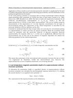
For three-dimensional bodies, the area A
p
in Equations (20) and
(21) is approximated by the plan view area of the hot body (Figure
19A). For horizontal cylinders, A
p
is the product of the length and
the diameter of the rod.
For vertical surfaces, the area A
p
in Equations (20) and (21) is the
area of the airstream (viewed from above) as the flow leaves the ver-
tical surface (Figure 19B). As the airstream moves upward on a ver-
tical surface, it appears to expand at an angle of approximately 4 to
5°. Thus, A
p
is given by
(22)
where
w = width of vertical surface, m
L = height of vertical surface, m
θ = angle of air stream expansion, °
For horizontal heated surfaces, A
p
is the surface area of the heated
surface, and L is the longest length (conservative) of the horizontal
surface or its diameter if it is round (Figure 19C).
If the heat transfer is caused by steam from a hot water tank,
(23)
where
q
conv
= convective heat transfer, kW
h
fg
= latent heat of vaporization, kJ/kg
G = steam generation rate, kg/(s·m
2
)
A
p
= surface area of the tank, m
2
At 100°C, the latent heat of vaporization is 2257 kJ/kg. Using
this value and Equation (23), Equation (20) simplifies to
(24)
The exhaust volumetric flow rate determined by Equation (20) or
(24) is the required exhaust flow rate when (1) a low canopy hood
of the same dimensions as the hot object or surface is used and (2)
side and back baffles are used to prevent room air currents from dis-
turbing the rising air column. If side and back baffles cannot be
used, the canopy hood size and the exhaust flow rate should be
increased to reduce the possibility of contaminant escape around the
hood. A good design provides a low canopy hood overhang equal to
40% of the distance from the hot process to the hood face on all
sides (ACGIH 1998). The increased hood flow rate can be calcu-
lated using the following equation:
(25)
where
Q
t
= total flow rate entering hood, m
3
/s
Q
o
*
= flow rate determined by Equation (20) or (24), m
3
/s
V
f
= desired indraft velocity through the perimeter area, m/s
A
f
= hood face area, m
2
A
p
= plan view area of Equation (20) or (24)
A minimum indraft velocity of 0.5 m/s should be used for most
design conditions. However, if room air currents are appreciable or
if the contaminant discharge rate is high and the design exposure
limit is low, higher values of V
f
may be required.
The volumetric flow rate for a high canopy hood over a round,
square, or rectangular (aspect ratio near 1) source can be predicted
using Equation (11) with adjustments discussed in the section on
Air and Contaminant Distribution with Buoyant Sources.
The diameter D
z
of the plume at any elevation z above the virtual
source can be determined by
Q
o
∗
2gR
pc
p
q
conv
× LA
p
2
13
⁄
=
Q
o
∗
0.038 q
conv
LA
p
2
()
13
⁄
=
Fig. 18 Influence of Hood Location on Contamination of Air
in the Operator’s Breathing Zone
A
p
wL θtan=
q
conv
h
fg
GA
p
=
Fig. 19 A
p
for Various Situations
Q
o
∗
5A
p
GL()
13
⁄
=
Q
t
Q
o
∗
V
f
A
f
A
p
–()+=
29.12 1999 ASHRAE Applications Handbook (SI)
(26)
High canopy hoods are extremely susceptible to room air cur-
rents. Therefore, they are typically much larger (often 100% larger)
than indicated by Equation (26) and are used only if a low canopy
hood cannot be used. The total flow rate exhausted from the hood
can be evaluated using Equation (25) if Q
o
is replaced by Q
z
.
According to Posokhin (1984), the canopy hood is effective
when
where
V
r
= room air velocity,m/s
z
o
= distance from virtual source to upper source level, m
V
z
= air velocity on thermal plume axis at hood face level, m/s
b = source width, m
Sidedraft Hoods
Sidedraft hoods are typically used when the contaminant is
drawn away from the operator’s breathing zone (Figure 2B). With a
buoyant source, a sidedraft hood requires a higher exhaust volumet-
ric flow rate than a low canopy hood. If a low canopy hood restricts
the operation, a sidedraft hood may be more cost-effective than a
high canopy hood. Examples of sidedraft hoods include multislot-
ted “pickling” hoods near welding benches (Figure 16), flanged
hoods (Figure 20), and slot hoods on tanks (Figure 21).
Sidedraft hoods should be installed with the low edge of the suc-
tion area at the level of the top of the heat source. The distance b
between the hood and the source may vary depending on the width
of the source (Figure 22); maximum b is equal to the width B of the
source. Based on studies by Kuz’mina (1959), the following airflow
rate through the sidedraft hood is recommended (Stroiizdat 1992):
(27)
where
c = nondimensional coefficient depending on hood design and loca-
tion relative to contaminant source [see Equations (28) and (29)]
q
conv
= convective component of the heat source, W
H = vertical distance from source top surface to hood center, m
B = source width, m
For a hood without a screen (Figure 22A),
(28)
For a hood with a screen (Figure 22B),
(29)
where m = 1, when b/B = 0; m = 1.5, when b/B = 0.3; m = 1.8 when
b/B = 1, and m = 2 when b/B > 1.
For open vessels, the contaminant can be controlled by a lateral
exhaust hood, which exhausts air through slots on the periphery of
the vessel. The hood capturing effectiveness depends on the exhaust
airflow rate and the hood design; however, it is not influenced by air
velocity through the slot. Hoods are designed with air exhaust from
one side of the vessel or from two sides. Air exhaust from two sides
requires a lower exhaust airflow rate. In most applications, a hood
with a vertical face (Figure 23A) is used when the distance h
l
D
z
0.5z
0.88
=
V
r
zz
o
+()
V
z
b
0.35≤
Q
o
∗
cq
conv
13
⁄
HB+()
53
⁄
=
c 280
I
HB+
23
⁄
=
c 280m
I
HB+
=
Fig. 20 Hood on Bench
Fig. 21 Sidedraft Hood and Slot Hood on Tank
Fig. 22 Schematics of Sidedraft Hood on Work Bench
Fig. 23 Schematics of Sidedraft Slot Hood on Tank
Industrial Local Exhaust Systems 29.13
between the vessel edge and the liquid level is smaller than 100 mm
(Stroiizdat 1992). When h
l
> 100 mm, hoods with the slot tipped
over to the liquid surface (Figure 23B) are more effective.
Stroiizdat (1992) recommends the following exhaust airflow rate
from one- and two-sided lateral slot hoods:
(30)
where
B = vessel width, m
l = vessel length, m
h = vertical distance between the liquid level and the hood face center, m
K
1
= hood design coefficient: K
1
= 1 for two-sided hood; K
1
= 1.8 for
one-sided hood
K
∆t
= coefficient reflecting liquid temperature (see Table 4)
K
t
= coefficient reflecting process toxicity (from 1 to 2; e.g., for electro-
plating tanks, K
t
= 2)
A more cost-effective alternative to a one- or two-sided lateral
hood is a push-pull hood, described in the section on Jet-Assisted
Hoods.
Downdraft Hoods
Downdraft hoods should be considered only when overhead or
sidedraft hoods are impractical. Air can be exhausted through a slot-
ted baffle (e.g., downdraft cutting table—see Figure 24) or through
a circular slot with a round source (Figure 25A) or two linear slots
along the long sides of a rectangular source (Figure 25B). To
achieve higher capturing effectiveness, the exhaust should be
located as close to the source as possible. Capturing effectiveness
decreases with an increase in source height and increases when the
top of the source is located below the hood face surface. With a
buoyant source, the air velocity induced by the exhaust should be
equal to or greater than the air velocity in the plume above the
source (Posokhin 1984).
The target airflow rate for a circular downdraft hood is
(31)
For a double linear slot downdraft hood,
(32)
where
d = source diameter, m
l = source length, m
b = source width, m
= convective heat component from the source vertical surfaces, W
= convective heat component from the source horizontal surface,
W
K
1
= coefficient accounting for hood geometry that can be evaluated
using graphs in Figure 25
K
v
= coefficient accounting for room air movement V
r
= for circular downdraft hood (33)
= for double slot downdraft hood (34)
Example 3. A downdraft hood is to be designed to capture a contaminant
from a rectangular source l × b × h = 0.6 m × 0.5 m × 0 m. Convective
heat component of the source q
conv
= 1000 W. Room air movement V
r
=
0.4 m/s. Two exhaust slots with a width b = 100 mm are located at the
distance B
1
= 0.6 m and B
2
= 0.8 m. Determine the exhaust airflow rate.
Solution: Using the graph in Figure 25 for B
2
/B
1
= 0.8/0.6 = 1.33, and
B
1
/b = 0.6/0.5 = 1.2, obtain K
1
= 5. Coefficient K
v
accounting for room
air movement [Equation (34)] is
Table 4 K
∆t
Coefficient Values
Liquid-to-Air Temperature Difference,
K
01020304050607080
K
∆t
1 1.16 1.31 1.47 1.63 1.79 1.94 2.1 2.26
Fig. 24 Downdraft Welding TableFig. 24 Downdraft Welding Table
Q
o
∗
1400 0.53
Bl
Bl+
h+
13
⁄
BlK
1
K
∆
t
K
t
=
Q
o
∗
0.0314 q
conv
d
5
()
13
⁄
10.06
q
conv
vert
q
conv
horiz
–
K
1
K
v
=
Fig. 25 K
1
Coefficient Evaluation for Downdraft Hoods
Q
o
∗
0.05q
conv
13
⁄
lbK
1
K
v
=
q
conv
vert
q
conv
horiz
1 44.7 V
r
3
d
q
conv
+
1 44.7
V
r
3
b
q
conv
+
K
v
1 44.77 0.4
3
0.5
1000
+1.25==
Industrial Local Exhaust Systems 29.15
where
(36)
V
min
= minimum velocity along jet, m/s
∆p = excessive pressure inside the process equipment, Pa
ρ
air
= density of room air, kg/m
3
ρ
g
= density of gas mixture releasing through the aperture in the pro-
cess equipment, kg/m
3
The supply and exhaust airflow rates Q
sup
and Q
o
, m
3
/s,
can be
determined as follows:
For a nonattached jet,
(37)
(38)
For a wall jet,
(39)
(40)
where
= from graph in Figure 27
= relative width of exhaust hood
= B/2l for a nonattached jet and B/l for a wall jet
B = width of exhaust hood, m
a = length of exhaust hood, m
b = width of supply slot, m
K
1
= coefficient accounting for hood geometry can be evaluated using
graphs in Figure 28
K
v
= coefficient accounting for room air movement V
r
= (41)
The following are some design considerations:
• Push-pull hoods are economically feasible if l > 1 m.
• The jet should be considered a wall jet when the distance H
between the supply nozzle and the vertical surface is smaller than
0.15l. Otherwise, the jet is nonattached.
• When flange width h > H + B, the hood is treated as an opening in
an infinite surface; when h ≤ H + B, the hood is treated as free-
standing.
• The value of the minimum velocity V
min
along the jet should be
greater than 1.5 m/s.
• The width b of the supply air slot is typically chosen to be 0.01l.
However, it should be greater than 5 mm to prevent fouling. The
length a of the supply slot should be equal to the length of the
aperture.
• The supply air velocity V
o
should not exceed 1.5 m/s. This can be
achieved by selection of the appropriate slot width b.
Example 4. A push-pull hood is to capture a contaminant from an oven
aperture. The surplus pressure in the oven ∆p = 2 Pa, and the tempera-
ture inside the oven t
g
= 800°C (ρ
g
= 0.329 kg/m
3
). Canopy hood is
installed at the height of l = 1.2 m from the low edge of the oven aper-
ture. The hood projection B = 0.576 m, and the hood width is equal to
the aperture width a = 1.8 m; the aperture height is 1 m. The room air
velocity near the hood V
r
= 0.4 m/s and the room air temperature t
air
=
20°C (ρ
air
= 1.2 kg/m
3
). Determine the supply and exhaust airflow
rates.
Solution: Using the graph in Figure 27 for = 0.576/(2 × 1.2) = 0.24,
obtain = 1.
From Equations (35) and (36) obtain parameter C and velocity V
min
:
Assuming b = 0.025 m, calculate supply airflow rate [Equation (37)]:
Coefficient K
v
accounting for room air movement [Equation (41)]:
From the graph in Figure 28, K
1
= 1.
The exhaust airflow rate [Equation (38)]:
Push-Pull Hood above Contaminated Area. A canopy hood
with an incorporated slotted nozzle installed around the perimeter of
the hood is used to prevent contaminant transfer from contaminated
areas, for example, the operating zone of one or several welding
robots (Figure 29), where enclosing hoods or other types of nonen-
closing hoods are impractical (U.S. Patent). Air supplied through
the nozzle creates steady air curtain protection along the contour.
Due to the negative pressure created by the hood, the air curtain jet
turns at or below the level of the contaminant source toward the cen-
ter. To minimize the supply airflow rate, the nozzle is equipped with
a honeycomb attachment that produces a low-turbulence jet. The
width of the nozzle can be determined as follows:
(42)
C
1
13.74ρ
g
ρ
air
⁄()+
=
Q
sup
0.435
V
min
V
min
abl=
Q
sup
0.205
V
min
V
min
alK
1
K
v
=
Q
sup
0.31
V
min
V
min
abl=
Q
sup
0.103
V
min
V
min
alK
1
K
v
=
V
min
Fig. 29 Push-Pull Hood over Welding Robot
B
1
V
r
V
min
+
B
V
min
C
1
1 3.74 0.329 1.2
⁄()
+
0.494==
V
min
9.9
2
0.329
1 142 0.494
2
×
+1–
89 0.494
2
×
5.59 m/s==
Q
sup
0.435
5.59
1
1.8
××
0.025 1.2
×
0.76 m
3
s
⁄
==
K
v
1
0.4
5.59
+1.07==
Q
sup
0.205
5.59
1
1.8
××
1.2 1
××
1.07
×
2.65 m
3
s
⁄
==
b
AP⁄
45
A
PH
2
0.566
H
b
1–
2
0.25 0.566
H
b
1+
2
–
=
29.16 1999 ASHRAE Applications Handbook (SI)
where
b = nozzle width, m
A = hood cross-sectional area, m
2
P = hood perimeter, m
H = height of hood above contaminant source, m
Push-Pull Protection System. These systems are used (Strongin
et al. 1986; Strongin and Marder 1988) to prevent contaminant
release from process equipment when the process requires that
entering and/or exiting apertures remain open (e.g., conveyer paint-
ing chambers, cooling tunnels, etc.). The open aperture must be
equipped with a tunnel and supply and exhaust air systems (Figure
30). The aperture is protected by the air jet(s) supplied through one
or two slots installed along one side or two opposite sides of the tun-
nel and directed at angle α = 80 to 85°
to the tunnel cross section. Air
supplied through the slot(s) is thus directed toward the incoming
room air. Moving along the tunnel, the jet(s) slow down, and their
dynamic pressure is converted into static pressure, preventing room
air from entering the chamber. After reaching the point with a zero
centerline velocity, the jet(s) make a U-turn and redirect into the
chamber. The air jet(s) can be supplied vertically (with supply air
ducts installed along vertical walls) or horizontally (with supply air
ducts installed along horizontal walls). The distance X (Figure 30)
from the entrance of a tunnel (with cross-sectional area B × H) to the
supply slot location should be greater than or equal to 5B with a sin-
gle vertical jet (5H with a single horizontal jet) and 2.5B (2.5H)
when air is supplied by two jets.
The air supply slot is equipped with diverging vanes (angle β
between 30 to 90°) creating an air jet with an increased angle of
divergence; the number n of these vanes should be greater than or
equal to β/10. The increased angle of divergence of supply air jets
allows a decrease in the distance X between the tunnel entrance and
the slot.
Airflow rate supplied by the jet is determined as
(43)
where
A
o
= cross-sectional area of the tunnel, m
2
b
o
= supply slot width, m
L
o
= supply slot length, m
J = supply jet parameter
= (44)
for
∆p = chamber to room pressure difference, Pa
= (45)
H = chamber height, m
g = gravitational acceleration, 9.8 m/s
2
ρ
room
= room chamber air density, kg/m
3
ρ
c
= chamber air density, kg/m
3
The minimum airflow rate to be exhausted outside from the
chamber and the corresponding amount of outdoor air to be supplied
through the slot should dilute the contaminants in the chamber to the
desired concentration. In the case of prevention of contaminant
release from a drying chamber, the solvent vapor concentration
should not exceed 25% of the lower explosive limit C
exp(min)
. In this
case, the exhaust airflow rate can be determined as follows:
(46)
where
G = amount of vapor release into the chamber, mg/s
K = coefficient accounting for the nonuniformity of solvent evapora-
tion and other irregularities; typically,
C
exp(min)
= lower explosive limit of pollutant, mg/m
3
OTHER LOCAL EXHAUST SYSTEM
COMPONENTS
Duct Design and Construction
Duct Considerations. The second component of a local exhaust
ventilation system is the duct through which contaminated air is
transported from the hood(s). Round ducts are preferred because
they (1) offer a more uniform air velocity to resist settling of mate-
rial and (2) can withstand the higher static pressures normally found
in exhaust systems. When design limitations require rectangular
ducts, the aspect ratio (height-to-width ratio) should be as close to
unity as possible.
Minimum transport velocity is the velocity required to trans-
port particulates without settling. Table 5 lists some generally
accepted transport velocities as a function of the nature of the con-
taminants (ACGIH 1998). The values listed are typically higher
than theoretical and experimental values to account for (1) damage
to ducts, which would increase system resistance and reduce volu-
metric flow and duct velocity; (2) duct leakage, which tends to
decrease velocity in the duct system upstream of the leak; (3) fan
wheel corrosion or erosion and/or belt slippage, which could reduce
fan volume; and (4) reentrainment of settled particulate caused by
improper operation of the exhaust system. Design velocities can be
higher than the minimum transport velocities but should never be
significantly lower.
When particulate concentrations are low, the effect on fan power
is negligible. Standard duct sizes and fittings should be used to cut
cost and delivery time. Information on available sizes and the cost
of nonstandard sizes can be obtained from the contractor(s).
Q
o
∗
A
o
b
o
L
o
∆p
J
=
α
sin 2.5
A
o
A
c
2.13 1 ψ
+
()
2
ψ
11
ψ⁄
+
2
ψ
2
–++
ψ
Q
exh
Q
o
=
0.5
gH
ρ
room
ρ
c
–
()
Q
exh
GK
0.25C
min
()
exp
=
2 K 5
≤≤
Table 5 Contaminant Transport Velocities
Nature of Contaminant Examples Minimum Transport Velocity, m/s
Vapor, gases, smoke All vapors, gases, smoke Usually 5 to 10
Fumes Welding 10 to 13
Very fine light dust Cotton lint, wood flour, litho powder 13 to 15
Dry dusts and powders Fine rubber dust, molding powder dust, jute lint, cotton dust, shavings (light), soap
dust, leather shavings
15 to 20
Average industrial dust Grinding dust, buffing lint (dry), wool jute dust (shaker waste), coffee beans, shoe dust,
granite dust, silica flour, general material handling, brick cutting, clay dust, foundry
(general), limestone dust, asbestos dust in textile industries
18 to 20
Heavy dust Sawdust (heavy and wet), metal turnings, foundry tumbling barrels and shakeout, sand-
blast dust, wood blocks, hog waste, brass turnings, cast-iron boring dust, lead dust
20 to 23
Heavy and moist dust Lead dust with small chips, moist cement dust, asbestos chunks from transite pipe
cutting machines, buffing lint (sticky), quicklime dust
23 and up
Source: Adapted from Industrial Ventilation: A Manual of Recommended Practice (ACGIH 1998).
29.18 1999 ASHRAE Applications Handbook (SI)
Duct Size Determination. The size of the round duct attached to
the hood can be calculated using Equation (1) for the volumetric
flow rate and Table 5 for the minimum transport velocity.
Example 5. Suppose the contaminant captured by the hood in Example 1
requires a minimum transport velocity of 15 m/s. What diameter round
duct should be specified?
Solution: From Equation (1), the duct area required is
Generally, the area calculated will not correspond to a standard duct
size. The area of the standard size chosen should be less than that calcu-
lated. For this example, a 225 mm diameter duct with an area of 0.0398
m
2
should be chosen. The actual duct velocity is then
Duct Losses. Chapter 32 of the 1997 ASHRAE Handbook—Fun-
damentals covers the basics of duct design and the design of metal-
working exhaust systems. The design method presented there is
based on total pressure loss, including the fitting coefficients;
ACGIH (1998) calculates static pressure loss. Loss coefficients can
be found in Chapter 32 of the 1997 ASHRAE Handbook—Funda-
mentals and in the ASHRAE Duct Fitting Database (ASHRAE
1994), which runs on a personal computer.
For systems conveying particulates, elbows with a centerline
radius-to-diameter ratio (r/D) greater than 1.5 are the most suitable.
If r/D ≤ 1.5, abrasion in dust-handling systems can reduce the life of
elbows. Elbows, especially those with large diameters, are often
made of seven or more gores. For converging flow fittings, a 30°
entry angle is recommended to minimize energy losses and abrasion
in dust-handling systems (Fitting ED5-1 in Chapter 32 of the 1997
ASHRAE Handbook—Fundamentals).
Where exhaust systems handling particulates must allow for a
substantial increase in future capacity, required transport velocities
can be maintained by providing open-end stub branches in the main
duct. Air is admitted through these stub branches at the proper pres-
sure and volumetric flow rate until the future connection is installed.
Figure 31 shows such an air bleed-in. The use of outside air mini-
mizes replacement air requirements. The size of the opening can be
calculated by determining the pressure drop required across the ori-
fice from the duct calculations. Then the orifice velocity pressure
can be determined from one of the following equations:
(47)
or
(48)
where
p
v,o
= orifice velocity pressure, Pa
∆p
t,o
= total pressure to be dissipated across orifice, Pa
∆p
s,o
= static pressure to be dissipated across orifice, Pa
C
o
= orifice loss coefficient referenced to the velocity at the orifice
cross-sectional area, dimensionless (Figure 15)
Equation (47) should be used if total pressure through the system
is calculated; Equation (48) should be used if static pressure through
the system is calculated. Once the velocity pressure is known, Equa-
tion (15) or (16) can be used to determine the orifice velocity. Equa-
tion (1) can then be used to determine the orifice size.
Integrating Duct Segments. Most systems have more than one
hood. If the pressures are not designed to be the same for merging
parallel airstreams, the system adjusts to equalize pressure at the
common point; however, the flow rates of the two merging air-
streams will not necessarily be the same as designed. As a result, the
hoods can fail to control the contaminant adequately, exposing
workers to potentially hazardous contaminant concentrations. Two
design methods ensure that the two pressures will be equal. The pre-
ferred design self-balances without external aids. This procedure is
described in the section on Industrial Exhaust System Duct Design
in Chapter 32 of the 1997 ASHRAE Handbook—Fundamentals. The
second design, which uses adjustable balance devices such as blast
gates or dampers, is not recommended, especially when abrasive
material is conveyed.
Duct Construction. Elbows and converging flow fittings should
be made of thicker material than the straight duct, especially if abra-
sives are conveyed. In some cases, elbows must be constructed with
a special wear strip in the heel. When corrosive material is present,
alternatives such as special coatings or different duct materials
(fibrous glass or stainless steel) can be used. Industrial duct con-
struction is described in Chapter 16 of the 2000 ASHRAE Hand-
book—Systems and Equipment. Refer to SMACNA (1990) for
industrial duct construction standards.
Air Cleaners
Air-cleaning equipment is usually selected to (1) conform to fed-
eral, state, or local emissions standards and regulations; (2) prevent
reentrainment of contaminants to work areas; (3) reclaim usable
materials; (4) permit cleaned air to recirculate to work spaces and/or
processes; (5) prevent physical damage to adjacent properties; and
(6) protect neighbors from contaminants.
Factors to consider when selecting air-cleaning equipment
include the type of contaminant (number of components, particu-
late versus gaseous, and concentration), the contaminant removal
efficiency required, the disposal method, and the air or gas stream
characteristics. See Chapters 24 and 25 of the 2000 ASHRAE
Handbook—Systems and Equipment for information on equipment
for removing airborne contaminants. A qualified applications engi-
neer should be consulted when selecting equipment.
The cleaner’s pressure loss must be added to overall system pres-
sure calculations. In some cleaners, specifically some fabric filters,
the loss increases as operation time increases. The system design
should incorporate the maximum pressure drop of the cleaner, or
hood flow rates will be lower than designed during most of the duty
cycle. Also, fabric collector losses are usually given only for a clean
air plenum. A reacceleration to the duct velocity, with the associated
entry losses, must be calculated in the design phase. Most other
cleaners are rated flange-to-flange with reacceleration included in
the loss.
Air-Moving Devices
The type of air-moving device used depends on the type and con-
centration of contaminant, the pressure rise required, and the allow-
able noise levels. Fans are usually selected. Chapter 18 of the 2000
ASHRAE Handbook—Systems and Equipment describes available
A 0.702 15
⁄
0.047 m
2
==
V 0.702 0.0398
⁄
17.6 m/s==
Fig. 31 Air Bleed-In
p
vo
,
∆p
to
,
C
o
=
p
vo
,
∆p
so
,
C
o
1+
=
Industrial Local Exhaust Systems 29.19
fans and refers the reader to Air Movement and Control Association
(AMCA) Publication 201, Fans and Systems, for proper connection
of the fan(s) to the system. The fan should be located downstream of
the air cleaner whenever possible to (1) reduce possible abrasion of
the fan wheel blades and (2) create negative pressure in the air
cleaner so that air leaks into it and positive control of the contami-
nant is maintained.
In some instances, however, the fan is located upstream from the
cleaner to help remove dust. This is especially true with cyclone col-
lectors, for example, which are used in the woodworking industry.
If explosive, corrosive, flammable, or sticky materials are handled,
an injector can transport the material to the air-cleaning equipment.
Injectors create a shear layer that induces airflow into the duct.
Injectors should be the last choice because their efficiency seldom
exceeds 10%.
Energy Recovery
The transfer of energy from exhausted air to replacement air may
be economically feasible, depending on (1) the location of the
exhaust and replacement air ducts, (2) the temperature of the
exhausted gas, and (3) the nature of the contaminants being
exhausted. The efficiency of heat transfer depends on the type of
heat recovery system used. Rotary air-to-air exchangers have the
best efficiency, 70-80%. Cross flow fixed-surface plate exchangers
and energy recovery loops with liquid coupled coils have efficien-
cies of 50 and 60% (Aro and Kovula 1992).
If exhausted air contains particulate matter (e.g., dust, lint) or oil
mist, the exhausted air should be filtered to prevent fouling the heat
exchanger. If the exhausted air contains gaseous and vaporous con-
taminants such as hydrocarbons and water-soluble chemicals, their
effect on the heat recovery device should be investigated (Aro and
Kovula 1992).
Exhaust Stacks
The exhaust stack must be designed and located to prevent the
reentrainment of discharged air into supply system inlets. The build-
ing’s shape and surroundings determine the atmospheric airflow
over it. Chapter 15 of the 1997 ASHRAE Handbook—Fundamentals
and Chapter 43 of this volume cover exhaust stack design.
If rain protection is important, stackhead design is preferable to
weathercaps. Weathercaps, which are not recommended, have three
disadvantages:
1. They deflect air downward, increasing the chance that contam-
inants will recirculate into air inlets.
2. They have high friction losses.
3. They provide less rain protection than a properly designed
stackhead.
Figure 32 contrasts the flow patterns of weathercaps and stack-
heads. Loss data for weathercaps and stackheads are presented in
the ASHRAE Duct Fitting Database (ASHRAE 1994). Losses in
the straight duct form of stackheads are balanced by the pressure
regain at the expansion to the larger-diameter stackhead.
OPERATION
System Testing
After installation, an exhaust system should be tested to ensure
that it operates properly with the required flow rates through each
hood. If the actual installed flow rates are different from the design
values, they should be corrected before the system is used. Testing
is also necessary to obtain baseline data to determine (1) compliance
with federal, state, and local codes; (2) by periodic inspections,
whether maintenance on the system is needed to ensure design oper-
ation; (3) whether a system has sufficient capacity for additional
airflow; and (4) whether system leakage is acceptable. AMCA Pub-
lication 203 and Chapter 9 of ACGIH (1998) contain detailed infor-
mation on the preferred methods for testing systems.
Operation and Maintenance
Periodic inspection and maintenance are required for the proper
operation of exhaust systems. Systems are often changed or dam-
aged after installation, resulting in low duct velocities and/or incor-
rect volumetric flow rates. Low duct velocities can cause the
contaminant to settle and plug the duct, reducing flow rates at the
affected hoods. Adding hoods to an existing system can change vol-
umetric flow at the original hoods. In both cases, changed hood vol-
umes can increase worker exposure and health risks. The
maintenance program should include (1) inspecting ductwork for
particulate accumulation and damage by erosion or physical abuse,
(2) checking exhaust hoods for proper volumetric flow rates and
physical condition, (3) checking fan drives, and (4) maintaining air-
cleaning equipment according to manufacturers’ guidelines.
REFERENCES
ACGIH. 1998. Industrial ventilation: A manual of recommended practice,
23rd edition. Committee on Industrial Ventilation, American Conference
of Governmental Industrial Hygienists, Cincinnati, OH.
Aksenov, A.A. and A.V. Gudzovskii. 1994. Numerical simulation of turbu-
lent thermal plumes in the stratified space. Proceedings of the First
National Conference on Heat Transfer. Part 2—Free Convection. 21-25
November. Moscow (in Russian).
Alden, J.L. and J.M. Kane. 1982. Design of Industrial Ventilation Systems,
5th ed. Industrial Press, New York.
AMCA. 1995. Fans and systems. Publication 201-95. Air Movement and
Control Association International, Arlington Heights, IL.
AMCA. 1995. Field performance measurement of fan systems. Publication
203-95.
Anichkhin, A.G. and G.N. Anichkhina. 1984. Ventilation of laboratories in
Research Institutions. In “Energy efficiency improvement of mechanical
systems”. Nauka, Moscow.
Aro, T. and K. Kovula. 1992. Learning from experiences with Industrial
Ventilation. Center for the Analysis and Dissemination of Demonstrated
Energy Technologies. AIR-IX Consulting Engineers, Finland.
ASHRAE. 1994. Duct fitting database.
Bastress, E., J. Niedzwecki, and A. Nugent. 1974. Ventilation required for
grinding, buffing, and polishing operations. U.S. Department of Health,
Education, and Welfare. NIOSH. Publication No. 75-107. Washington,
D.C.
Boshnyakov, E.N. 1975. Local exhaust with air curtains. Water Supply and
Sanitary Techniques, #3. Moscow (in Russian).
Fig. 32 Comparison of Flow Pattern for Stackheads
and Weathercaps
29.20 1999 ASHRAE Applications Handbook (SI)
Burgess, W.A., M.J. Ellenbecker, and R.D. Treitman. 1989. Ventilation for
control of the work environment. John Wiley and Sons, New York.
Caplan, K.J. and G.W. Knutson. 1977. The effect of room air challenge on
the efficiency of laboratory fume hoods. ASHRAE Transactions 83(1):
141-156.
Caplan, K.J. and G.W. Knutson. 1978. Laboratory fume hoods: Influence of
room air supply. ASHRAE Transactions 82(1):522-37.
Cesta, T. 1988. Capture of pollutants from a buoyant point source using a
lateral exhaust hood with and without assistance from air curtains. Pro-
ceedings of the 2nd International Symposium on Ventilation for Contam-
ination Control, Ventilation ’88. Pergamon Press, UK.
Chambers, D.T. 1993. Local exhaust ventilation: A philosophical review of
the current state-of-the-art with particular emphasis on improved worker
protection. DCE, Leicester, UK.
Davidson, L. 1989. Numerical simulation of turbulent flow in ventilated
rooms. Ph.D. thesis, Chalmers University of Technology, Sweden.
DallaValle, J.M. 1952. Exhaust hoods, 2nd ed. Industrial Press, New York.
Elinskii, I.I. 1989. Ventilation and heating of galvanic shops of machine-
building plants. Mashinostroyeniye, Moscow (in Russian).
Elterman, V.M. 1980. Ventilation of chemical plants. Moscow: KHIMIA (in
Russian).
Fletcher, B. 1977. Center line velocity characteristics of rectangular
unflanged hoods and slots under suction. Ann. Occup. Hyg. 20:141-46.
Fuller, F.H. and A.W. Etchells. 1979. The rating of laboratory hood perfor-
mance. ASHRAE Journal 21(10):49-53.
Garrison, R.P. 1977. Nozzle performance and design for high-velocity/low-
volume exhaust ventilation. Ph.D. thesis. University of Michigan, Ann
Arbor, MI.
Hagopian, J.H. and E.K. Bastress. 1976. Recommended industrial ventila-
tion guidelines. U.S. Department of Health, Education, and Welfare,
NIOSH. Publication No. 76-162. Washington, D.C.
Heinsohn, R.J. 1991. Industrial ventilation: Engineering principles. John
Wiley and Sons, New York.
Hemeon, W.C.L. 1963. Plant and process ventilation, p. 77. Industrial Press,
New York.
Hinds, W. 1982. Aerosol technology: Properties, behavior, and measure-
ment of airborne particles. John Wiley and Sons, New York.
Holman, J.P. 1989. Heat transfer. McGraw Hill, Singapore.
Idelchik, I.E., G.R. Malyavskaya, O.G. Martynenko, and E. Fried. 1986.
Handbook of hydraulic resistance, 2nd ed. Hemisphere Publishing Cor-
poration, subsidiary of Harper and Row, New York.
Ivanitskaya, M.Yu., and V.I. Kunitsa. 1974. Experimental studies of thermal
plumes above a round heat source. Proceedings of TsNIIPromzdanii.
V.37. TsNIIPromzdanii, Moscow (in Russian).
Kofoed, P. 1991. Thermal plumes in ventilated rooms. Ph.D. thesis, Aalborg
University, Denmark.
Kofoed, P. and P.V. Nielsen. 1991. Thermal plumes in ventilated rooms—
Vertical volume flux influenced by enclosing walls. 12th AIVC Confer-
ence, Ottawa.
Kuz’mina, L.V. 1959. Sidedraft and cornerdraft hoods. Transactions of the
Institutes for Labor Protection of the VTsSPS (All-Union Central
Council of Trade Unions). No. 2. Moscow: PROFIZDAT, pp. 25-34 (in
Russian).
Ljungqvist, B. and C. Waering. 1988. Some observations on “modern”
design of fume cupboards. Proceedings of the 2nd International Sym-
posium on Ventilation for Contaminant Control, Ventilation ’88. Per-
gamon Press, UK.
Morton, B.R., G. Taylor, and J.S. Turner. 1956. Turbulent gravitational con-
vection from maintained and instantaneous sources. Proceedings of
Royal Society. Vol. 234A, p. 1.
Mundt, E. 1992. Convection flows in rooms with temperature gradients—
Theory and measurements. RoomVent ’92. Proceedings of the Third
International Conference on Air Distribution in Rooms. Vol. 3. Aalborg.
Nielsen, P.V. 1993. Displacement ventilation—Theory and design. Depart-
ment of Building Technology and Structural Engineering. Aalborg Uni-
versity, Denmark.
NFPA. 1995. Standard for ovens and furnaces. ANSI/NFPA Standard 86-95.
National Fire Protection Association, Quincy, MA.
Popiolec, Z. 1981. Problems of testing and mathematical modeling of
plumes above human body and other extensive heat sources. A4-seria.
No. 54. KTH, Stockholm.
Posokhin, V.N. 1984. Design of local ventilation systems for process equip-
ment with heat and gas release. Mashinostroyeniye, Moscow (in Rus-
sian).
Posokhin, V.N. and V.A. Broida. 1980. Local exhausts incorporated with air
curtains. Hydromechanics and heat transfer in sanitary technique equip-
ment. KHTI, Kazan (in Russian).
Posokhin, V.N. and A.M. Zhivov. 1997. Principles of local exhaust design.
Proceedings of the 5th International Symposium on Ventilation for Con-
taminant Control. Vol.1. The Canadian Environment Industry Associa-
tion (CEIA), Ottawa.
Romeyko, N.F., N.E. Siromyatnikova, and E.V. Schibraev. 1976. Design of
air curtains near an oven opening supplied with a hood. Heating and Ven-
tilation. Proceedings of the A.I. Mikoyan Institute of Civil Engineers (in
Russian).
Schaelin, A. and P. Kofoed. 1992. Numerical simulation of thermal plumes
in rooms. RoomVent ’92. Proceedings of the Third International Confer-
ence on Air Distribution in Rooms. Vol. 1. Aalborg, Denmark.
Schmidt, W. 1941. Turbulente Ausbreitung eines Stromes erhitzter Luft.
ZAMM. Bd. 21 # 5 (in German).
Sciola, V. 1993. The practical application of reduced flow push-pull plating
tank exhaust systems. 3rd International Symposium on Ventilation for
Contaminant Control, Ventilation ’91 (Cincinnati, OH).
Shepelev, I.A. 1961. Turbulent convective stream above a heat source. Pro-
ceedings of Acad. Sci. USSR. Mechanics and Machinery Construction
#4 (in Russian).
Skäret, E. 1986. Ventilasjonsteknikk. Textbook. Institute of Heating, Venti-
lation and Sanitary Techniques, NTH. Trondheim (in Norwegian).
Skistad, H. 1994. Displacement ventilation. Research Studies Press, John
Wiley and Sons, West Sussex. UK.
SMACNA. 1977. Round industrial duct standards. Sheet Metal and Air
Conditioning Contractors’ National Association, Vienna, VA.
SMACNA. 1980. Rectangular industrial duct construction standards.
Stoler, V.D. and Yu. L. Savelyev. 1977. Push-pull systems design for etching
tanks. Heating, Ventilation, Water Supply, and Sewage Systems Design
8(124). TsINIS, Moscow (in Russian).
Stroiizdat. 1992. Designer’s guide. Ventilation and air conditioning, 4th ed.
Part 3(1). Stroiizdat, Moscow (in Russian).
Strongin, A.S. and M.L. Marder. 1988. Complex solution of painting shops
ventilation. Proceedings of the conference “Utilization of Natural
Resources and New Ventilation and Dust Transportation Systems
Design”. Penza (in Russian).
Strongin, A.S., M.Yu. Ivanitskaya, and E.A. Visotskaya. 1986. Studies of the
application of air curtains in tunnels for local ventilation. Heating and
Ventilation. Transactions of TsNIIpromzdanii (in Russian).
Tyaglo, I.G. and I.A. Shepelev. 1970. Air flow near an exhaust opening.
Vodosnabzheniye i Sanitarnaya Tekhnika #5, pp. 24-25 (in Russian).
U.S. Patent. Device for removal of deleterious impurities from room atmo-
sphere. U.S. Patent # 5,716,268. February 1998.
Zeldovitch, Y.B. 1937. Fundamental principles for free convective
plumes. Journal of Experimental and Technical Physics 7(12). Mos-
cow (in Russian).
Zhivov, A.M. 1993. Principles of source capturing and general ventilation
design for welding premises. ASHRAE Transactions 99(1):979-86.
Zhivov, A.M. and J.T. Ashe. 1997. Principles of welding fume control. Pro-
ceedings of the 5th International Symposium on Ventilation for Contam-
inant Control. Vol. 1. The Canadian Environment Industry Association
(CEIA), Ottawa.
Zhivov, A.M., L.L. Christianson, and G.L. Riskowski. 1997. Influence of
space air movement on hood performance. ASHRAE Research Project
RP-744.
BIBLIOGRAPHY
AICVF. 1991. Principles of airflow applied to the HVAC field. Collection
des guides de l’AICVF. Association d’Ingenierie de Chauffage, Ventila-
tion et Froid, Paris (in French).
Balchin, N.C. (Ed.) 1991. Health and safety in welding and allied processes,
4th ed. Abington Publishing, Cambridge, UK.
Baturin, V.V. 1972. Fundamentals of industrial ventilation, 3rd English ed.
Pergamon Press, New York.
Braconnier, R. 1988. Bibliographic review of velocity field in the vicinity of
local exhaust hood openings. American Industrial Hygiene Association
Journal 49(4):185-98.
Brandt, A.D., R.J. Steffy, and R.G. Huebscher. 1947. Nature of air flow at
suction openings. ASHVE Transactions 53:55-76.
British Occupational Hygiene Society (BOHS). 1987. Controlling airborne
contaminants in the workplace. Technical Guide No. 7. Science Review
Ltd. and H&H Sci. Consult., Leeds, UK.
Industrial Local Exhaust Systems 29.21
CIBSE. 1986. Guide B: Installation and equipment data. Chartered Institu-
tion of Building Services Engineers, London.
Elterman V. 1985. Pollution control at chemical and oil-chemical industry.
Chemia, Moscow (in Russian).
Flynn, M.R. and M.J. Ellenbecker. 1985. The potential flow solution for air
flow into a flanged circular hood. American Industrial Hygiene Journal
46(6):318-22.
Glinski, M. 1978. Influence of disturbing streams on efficiency of suction
pipes in local ventilation installations. Transactions of Central Institute
for Labor Protection 28:45-60. Warsaw.
Goodfellow, H.D. 1985. Advanced design of ventilation systems for con-
taminant control. Chem Eng. Monograph 231. Elsevier, Amsterdam.
Goodfellow, H.D. 1986. Ventilation ’85 (Conference Proceedings). Elsevier,
Amsterdam.
Grimitlyn, M. et al. 1983. Ventilation and heating of plastics processing
shops. Chemia, Leningrad (in Russian).
Grimitlyn, M. et al. 1993. Ventilation and heating of shops of machinery
building plants. 2nd ed. Mashinostroyeniye, Moscow (in Russian).
Heinsohn, R.J., K.C. Hsieh, and C.L. Merkle. 1985. Lateral ventilation sys-
tems for open vessels. ASHRAE Transactions 91(1B):361-82.
Huebener, D.J. and R.T. Hughes. 1985. Development of push-pull ventila-
tion. American Industrial Hygiene Association Journal 46(5):262-67.
INRS. 1983. Ventilation of foundry knock-out workplace. Guide for venti-
lation practice #4. ED662. Institut National de Recherche et de Sécurité,
Paris (in French).
INRS. 1985. Extraction and air cleaning from oil mist. Guide for ventilation
practice #6. ED680 (in French).
INRS. 1986. General principles of ventilation. Guide for ventilation practice
#0. ED695 (in French).
INRS. 1987. Painting of large and/or bulky equipment. Guide for ventilation
practice #10. ED713 (in French).
INRS. 1988. Screen printing. Guide for ventilation practice #11. ED711 (in
French).
INRS. 1988. Ventilation of arc welding operations. Guide for ventilation
practice #8. ED668 (in French).
INRS. 1988. Ventilation of confined spaces. Guide for ventilation practice
#9. ED703 (in French).
INRS. 1989. Production processes in laminated polyester workshops. Guide
for ventilation practice #3. ED665 (in French).
INRS. 1989. Small articles gluing workshops. Guide for ventilation practice
#5. ED672 (in French).
INRS. 1989. Workroom air cleaning. Guide for ventilation practice #1.
ED657 (in French).
INRS. 1990. Ventilation of open surface tanks. Guide for ventilation prac-
tice #2. ED651 (in French).
INRS. 1991. Lead accumulator manufacturing. Guide for ventilation prac-
tice #13. ED746 (in French).
INRS. 1991. Ventilation of painting booths and workplace. Guide for venti-
lation practice #7. ED663 (in French).
INRS. 1992. Automobile radiator repairs. Guide for ventilation practice
#15. ED752 (in French).
INRS. 1992. Denture manufacturing workshops. Guide for ventilation prac-
tice #16. ED760 (in French).
INRS. 1992. Woodworking. Guide for ventilation practice #12. ED750 (in
French).
INRS. 1993. Use of powders. Guide for ventilation practice #17. ED767 (in
French).
Pozin, G.M. 1977. Calculation of the effect of limitation planes on suction
flows. Transactions of the Central Institute for Labor Protection of the
VCSPS 105:8-13. Profizdat, Moscow (in Russian).
Qiang, Y.L. 1984. The effectiveness of hoods in windy conditions. Kungl
Tekniska Hoggskolan. Stockholm, Sweden.
Safemazandarani, P. and H.D. Goodfellow. 1989. Analysis of remote recep-
tor hoods under the influence of cross-drafts. ASHRAE Transactions
95(1):465-71.
Sepsy, C.F. and D.B. Pies. 1973. An experimental study of the pressure
losses in converging flow fittings used in exhaust systems. Document PB
221 130. Prepared by Ohio State University for National Institute for
Occupational Health.
Shibata, M., R.H. Howell, and T. Hayashi. 1982. Characteristics and design
method for push-pull hoods: Part 1—Cooperation theory on air flow;
Part 2—Streamline analysis of push-pull flows. ASHRAE Transactions
88(1):535-70.
Silverman, L. 1942. Velocity characteristics of narrow exhaust slots. Journal
of Industrial Hygiene and Toxicology 24 (November):267.
Sutton, O.G. 1950. The dispersion of hot gases in the atmosphere. Journal of
Meteorology 7(5):307.
Ventilation ’85. 1986. Proceedings of the 1st International Symposium on
Ventilation for Contaminant Control. Elsevier Science Publishers,
Amsterdam.
Ventilation ’88. 1989. Proceedings of the 2nd International Symposium on
Ventilation for Contaminant Control. Elsevier Science Publishers,
Amsterdam.
Ventilation ’91. 1993. Proceedings of the 3nd International Symposium on
Ventilation for Contaminant Control. American Conference of Govern-
mental Industrial Hygienists (ACGIH), Cincinnati, OH.
Ventilation ’94. 1994. Proceedings of the 4th International Symposium on
Ventilation for Contaminant Control. Arbets Miljo Institutet (National
Institute of Occupational Health), Stockholm.
Ventilation ’97. 1997. Proceedings of the 5th International Symposium on
Ventilation for Contaminant Control. The Canadian Environment Indus-
try Association (CEIA), Ottawa.
Zarouri, M.D., R.J. Heinsohn, and C.L. Merkle. 1983. Computer-aided
design of a grinding booth for large castings. ASHRAE Transactions 89
(2A):95-118.
Zarouri, M.D., R.J. Heinsohn, and C.L. Merkle. 1983. Numerical computa-
tion of trajectories and concentrations of particles in a grinding booth.
ASHRAE Transactions 89(2A):119-35.
CHAPTER 30
KITCHEN VENTILATION
Cooking Effluent 30.1
Exhaust Hoods 30.1
Exhaust Systems 30.6
Replacement (Makeup)
Air Systems 30.9
System Integration and Balancing 30.9
Energy Considerations 30.11
Fire Protection 30.12
Operation and Maintenance 30.15
Residential Kitchen Ventilation 30.17
ITCHEN ventilation is a complex application of HVAC sys-
Ktems. System design includes aspects of air conditioning, fire
safety, ventilation, building pressurization, refrigeration, air distri-
bution, and food service equipment. Kitchens are in many build-
ings, including hotels, hospitals, retail malls, single- and multi-
family dwellings, and correctional facilities. Each of these building
types has special requirements for its kitchens, but many of the basic
needs are common to all.
Kitchen ventilation has at least two purposes: (1) to provide a
comfortable environment in the kitchen and (2) to enhance the
safety of personnel working in the kitchen and of other building
occupants. “Comfortable” in this context has different meanings
because, depending on the local climate, some kitchens are not air
conditioned. Obviously, the kitchen ventilation system can affect
temperature and humidity in the kitchen. The ventilation system can
also affect the acoustics of a kitchen.
The centerpiece of almost any kitchen ventilation system is an
exhaust hood, which is used primarily to remove effluent from
kitchens. Effluent includes the gaseous, liquid, and solid contami-
nants produced by the cooking process. These contaminants must
be removed for both comfort and safety. Effluent can range from
simply annoying to potentially life-threatening and, under certain
conditions, flammable. The arrangement of the food service equip-
ment and its coordination with the hood(s) greatly affect the oper-
ating costs of the kitchen.
HVAC system designers are most frequently involved in com-
mercial kitchen applications, in which cooking effluent contains
large amounts of grease or water vapor. Residential kitchens typi-
cally use a totally different type of hood. The amount of grease
produced in residential applications is significantly less than in
commercial applications, so the health and fire hazard is much
lower.
COOKING EFFLUENT
Effluent Generation
Cooking is the process of creating chemical and physical
changes in food by applying heat to the raw or precooked food.
Cooking improves edibility, taste, or appearance or delays decay. As
heat is applied to the food, effluent is released into the surrounding
atmosphere. This effluent includes heat that has not transferred to
the food, water vapor, and organic material released from the food.
The heat source, especially if it involves combustion, may release
other contaminants.
All cooking methods release some heat, some of which radiates
from all hot surfaces; but most is dissipated by natural convection
via a rising plume of heated air. Most of the effluent released from
the food and the heat source is entrained in this plume, so primary
contaminant control should be based on capturing and removing the
air and effluent that constitute the plume. A quantitative analysis, or
even a relative determination, of plume and combustion product
volumetric flow rates is not available at present.
Plume Behavior
The most common method of contaminant control is to install an
air inlet device (a hood) where the plume can enter it and be con-
veyed away by an exhaust system. The hood is generally located
above or behind the heated surface to intercept the normal upward
flow path. Understanding the behavior of the plume is central to
designing effective ventilation systems.
Effluent released from a noncooking cold process, such as metal
grinding, is captured and removed by placing air inlets so that they
catch forcibly ejected material, or by creating airstreams with suffi-
cient velocity to induce the flow of effluent into an inlet. This tech-
nique has led to an empirical concept of capture velocity that is
often misapplied to hot processes. Effluent released from a hot pro-
cess and contained in a plume may be captured by locating an inlet
hood so that the plume flows into it by buoyancy. The hood exhaust
rate must equal or slightly exceed the plume flow rate, but the hood
need not actively capture the effluent if the hood is large enough at
its height above the cooking operation to encompass the plume as it
expands during its rise. Additional exhaust airflow may be needed
to resist crosscurrents that carry the plume away from the hood.
A plume, in the absence of crosscurrents or other interference,
rises vertically. As it rises, it entrains additional air, which causes
the plume to enlarge and its average velocity and temperature to
decrease. In most cooking processes, the distance between the
heated surface and the hood is so short that entrainment is negligi-
ble, and the plume loses very little of its velocity or temperature
before it reaches the hood. If a surface parallel to the plume center-
line (e.g., a back wall) is located nearby, the plume will attach to the
surface by the Coanda effect. This tendency also directs the plume
into the hood.
Appliance Types (Steam, Electric, Solid Fuel, Gas)
The heat source affects the type and quantity of effluent released.
When steam is the heat source, it releases no contaminants because
it is contained in a closed vessel. Electric heating sources similarly
release no significant contaminants.
Solid (wood or charcoal) or gaseous (natural gas or liquefied
petroleum gas) fuels are common sources of heat for cooking. Their
combustion generates water vapor and carbon dioxide, and it may
also generate carbon monoxide and other potentially harmful gases.
These effluents must be controlled along with those released from
the food. In some cases, the food or its container is directly exposed
to the flame; as a result, the combustion effluent and the food efflu-
ent are mixed, and a single plume is generated. In other cases, such
as ovens, the combustion products are ducted to an outlet adjacent
to the plume, and the effluents still mix.
EXHAUST HOODS
The kitchen exhaust hood captures, contains, and evacuates
heat, smoke, odor, steam, grease, vapor, and other contaminants
generated from cooking in order to provide a safe, healthy, com-
fortable, and productive work environment for kitchen personnel.
The preparation of this chapter is assigned to TC 5.10, Kitchen Ventilation.
30.2 1999 ASHRAE Applications Handbook (SI)
This section discusses all aspects of kitchen hood design; it is based
primarily on model codes and standards in the United States.
The design, engineering, construction, installation, and mainte-
nance of commercial kitchen exhaust hoods are controlled by the
major nationally recognized standards (e.g., NFPA Standard 96)
and model codes. In some cases, local codes may prevail. Prior to
designing a kitchen ventilation system, the designer should identify
governing codes and consult the authority having jurisdiction. Local
authorities having jurisdiction may have amendments or additions
to these standards and codes.
Hood Types
Many types, categories, and styles of hoods are available, and
hood selection depends on many factors. Hoods are classified based
on whether they are designed to handle grease. Type I refers to
hoods designed for removal of grease and smoke, and Type II refers
to all other hoods. The model codes distinguish between grease-
handling and non-grease-handling hoods, but not all model codes
use Type I/Type II terminology. A Type I hood may be used where
a Type II hood is required, but the reverse is not allowed. However,
the characteristics of the cooking equipment under the hood, and not
the hood type, determine the requirements for the entire exhaust
system, including the hood.
A Type I hood is used for collection and removal of grease and
smoke. It includes (1) listed grease filters, baffles, or extractors for
removal of the grease and (2) fire suppression equipment. Type I
hoods are required over restaurant equipment, such as ranges, fry-
ers, griddles, broilers, ovens, and steam kettles, that produce smoke
or grease-laden vapors.
A Type II hood is for collection and removal of steam, vapor,
heat, and odors where grease is not present. It may or may not have
grease filters or baffles and typically does not have a fire suppres-
sion system. It is typically used over dishwashers, steam tables, and
so forth. The Type II hood is sometimes used over ovens, steamers,
or kettles if they do not produce smoke or grease-laden vapor and if
the authority having jurisdiction allows it.
Type I Hoods Categories
Type I hoods fall into two categories. One is the conventional
(nonlisted) category, which meets the design, construction, and per-
formance criteria of the applicable national and local codes. Con-
ventional
(nonlisted) hoods are not allowed to have fire-actuated
exhaust dampers.
The second category comprises hoods that are listed in Under-
writers Laboratories (UL) Standard 710. Listed hoods are not gen-
erally designed, constructed, or operated in accordance with
requirements of the model codes, but are constructed in accor-
dance with the terms of the hood manufacturer’s listing. This is
allowed because the model codes include exceptions for hoods
listed to show equivalency with the safety criteria of the model
code requirements.
The two basic subcategories of Type I listed hoods, as defined in
UL Standard 710, are exhaust hoods without exhaust dampers and
exhaust hoods with exhaust dampers. The UL listings do not distin-
guish between water-wash and dry hoods, except that water-wash
hoods with fire-actuated water systems are identified in UL’s prod-
uct directory.
All listed hoods are subjected to electrical tests, temperature
tests, and fire and cooking smoke capture tests. The listed exhaust
hood with exhaust damper includes a fire-actuated damper, typi-
cally located at the exhaust duct collar (and at the replacement air
duct collar, depending on the hood configuration). In the event of a
fire, the damper closes to prevent fire from entering the duct. Fire-
actuated dampers are permitted only as part of a hood listing.
Listed exhaust hoods with fire-actuated water systems are typi-
cally water-wash hoods in which the wash system also operates as
a fire-extinguishing system. In addition to meeting the requirements
of UL Standard 710, these hoods are tested under UL Standard 300
and may be listed for plenum extinguishment, duct extinguishment,
or both.
Type I Hoods—Grease Removal
Most grease removal devices in Type I hoods operate on the
same general principle—the exhaust air passes through a series of
baffles in which a centrifugal force that throws the grease particles
out of the airstream is created as the exhaust air passes around the
baffles. The amount of grease removed varies with the design of the
baffles, the air velocity, the temperature, the type of cooking, and
other factors. A recognized test protocol is not available at present.
Mesh filters cannot meet the requirements of UL Standard 1046 and
therefore cannot be used as primary grease filters. Grease removal
devices generally fall into the following categories:
• Baffle filter. The baffle filter is a series of vertical baffles
designed to capture grease and drain it into a container. The filters
are arranged in a channel or bracket for easy insertion and easy
removal from the hood for cleaning. Each hood usually has two or
more baffle filters. The filters are typically constructed of alumi-
num, steel, or stainless steel, and they come in various standard
sizes. Filters are cleaned by running them through a dishwasher or
by soaking and rinsing. NFPA Standard 96 requires that grease
filters be listed. Listed grease filters are tested and certified by a
nationally recognized test laboratory under UL Standard 1046.
• Removable extractor. Removable extractors are an integral
component of listed exhaust hoods designed to use them. They
are typically constructed of stainless steel and contain a series of
horizontal baffles designed to remove grease and drain it into a
container. Removable extractors come in various sizes. They are
cleaned by running them through a dishwasher or by soaking and
rinsing.
• Stationary extractor. The stationary extractor (also called a
water-wash hood) is an integral component of listed exhaust
hoods that use them. They are typically constructed of stainless
steel and contain a series of horizontal baffles that run the full
length of the hood. The baffles are not removable for cleaning.
The stationary extractor includes one or more water manifolds
with spray nozzles that, upon activation, wash the grease extrac-
tor with hot, detergent-injected water, removing accumulated
grease. The wash cycle is typically activated at the end of the day,
after the cooking equipment and fans have been turned off; how-
ever, it can be activated more frequently. The cycle lasts for 5 to
10 min, depending on the hood manufacturer, the type of cooking,
the duration of operation, and the water temperature and pressure.
Most water-wash hood manufacturers recommend a water tem-
perature of 55 to 80°C and water pressure of 200 to 550 kPa.
Average water consumption varies from 0.1 to 0.3 L/s per linear
metre of hood, depending on the hood manufacturer. Most water-
wash hood manufacturers provide a manual and/or an automatic
means of activating the water-wash system in the event of a fire.
Some manufacturers of water-wash hoods provide continuous
cold water as an option. The cold water
runs continuously during
cooking and may or may not be recirculated, depending on the
manufacturer. Typical cold water usage is 3.5 mL/s per linear
metre of hood. The advantage of continuous cold water
is that it
improves grease extraction and removal, partly through conden-
sation of the grease. Many hood manufacturers recommend con-
tinuous cold water
in hoods that are located over solid-fuel-
burning equipment, as the water also extinguishes hot embers that
may be drawn up into the hood and helps cool the exhaust stream.
UL Standards 1046 and 710 do not include grease extraction
tests because no industry-accepted tests are available at present in
the United States. Grease extraction rates published by filter and
hood manufacturers are usually derived from tests conducted by
Kitchen Ventilation 30.3
independent test laboratories retained by the manufacturer. Test
methods and results therefore vary greatly.
Type I Hoods—Styles
Figure 1 shows the six basic hood styles for Type I applications.
These style names are not used universally in all standards and
codes but are well accepted in the industry. The styles are as fol-
lows:
1. Wall-mounted canopy. Used for all types of cooking equipment
located against a wall.
2. Single-island canopy. Used for all types of cooking equipment
in a single-line island configuration.
3. Double-island canopy. Used for all types of cooking equipment
mounted back-to-back in an island configuration.
4. Back shelf. Used for counter-height equipment typically located
against a wall, but could be freestanding.
5. Eyebrow. Used for direct mounting to ovens and some dish-
washers.
6. Pass-over. Used over counter-height equipment when pass-over
configuration (from the cooking side to the serving side) is
required.
Type I Hoods—Sizing
The size of the exhaust hood in relation to cooking appliances is
an important aspect of hood performance. Usually the hood must
extend beyond the cooking appliances—on all open sides on can-
opy-style hoods and over the ends on back shelf and pass-over
hoods—to capture the expanding thermal currents rising from the
appliances. This overhang varies with the style of the hood, the dis-
tance between the hood and the cooking appliance, and the charac-
teristics of the cooking equipment. With back shelf and pass-over
hoods, the front of the hood must be kept behind the front of the
cooking equipment (set back) to allow head clearance for the
cooks. These hoods may require a higher front inlet velocity to catch
and contain the expanding thermal currents. All styles may have full
or partial side panels to close the area between the appliances and
the hood. This may eliminate the overhang requirement and gener-
ally reduces the exhaust flow rate requirement.
For conventional hoods, hood size is dictated by the prevailing
model code, and for listed hoods, by the terms of the manufacturer’s
listing. Typically, the overhang requirements applied to listed hoods
are similar to those for conventional hoods. General overhang
requirements are shown in Table 1.
Type I Hoods—Exhaust Flow Rates
Exhaust flow rate requirements to capture, contain, and remove
the effluent vary considerably depending on the hood style, the
amount of overhang, the distance from the cooking surface to the
hood, the presence and size of side panels, and the cooking equip-
ment and product involved. The hot cooking surfaces and product
vapors create thermal air currents that are received or captured by
the hood and then exhausted. The velocity of these currents depends
largely on the surface temperature and tends to vary from 75 mm/s
over steam equipment to 0.75 m/s over charcoal broilers. The actual
required flow rate is determined by these thermal currents, a safety
allowance to absorb crosscurrents and flare-ups, and a safety factor
for the style of hood.
Overhangs, the distance from the cooking surface to the hood,
and the presence or absence of side panels all help determine the
safety factor for different hood styles. Use of gas-fired cooking
equipment may require an additional allowance for the exhaust of
combustion products and combustion air. Because it is not practical
to place a separate hood over each piece of equipment, general prac-
tice is to categorize the equipment into four groups. While pub-
lished lists vary, and accurate documentation does not yet exist, the
following is a consensus opinion list (great variance in product or
volume could shift an appliance into another category):
1. Light duty, such as ovens, steamers, and small kettles (up to
200°C)
2. Medium duty, such as large kettles, ranges, griddles, and fryers
(up to 200°C)
3. Heavy duty, such as upright broilers, charbroilers, and woks (up
to 315°C)
4. Extra heavy duty, such as solid-fuel-burning equipment (up to
370°C)
The exhaust volumetric flow rate requirement is based on the
group of equipment under the hood. If there is more than one group,
the flow rate is based on the heaviest duty group unless the hood
design permits different rates over different sections of the hood.
For areas where model codes or other regional codes have been
adopted, the exhaust flow rate requirement for conventional hoods
is dictated by the codes; therefore, the manufacturers’ calculation
methods may not be used without consultation with the authority
having jurisdiction. The model code required exhaust flow rates for
conventional canopy hoods are typically calculated by multiplying
the area A of the hood opening by a given air velocity. Table 2 indi-
cates typical formulas, taken from the model codes, for determining
the exhaust flow rate Q for conventional canopy hoods. Some juris-
dictions may use the length of the open perimeter of the hood times
the vertical height between the hood and the appliance instead of the
horizontal hood area.
The International Mechanical Code (IMC) and some state codes
have alternate formulas that allow lower flow rates for equipment
that produces less heat and smoke; however, the IMC does require
1 m
3
/s per square metre of hood area for hoods covering charbroil-
ers. Back shelf and pass-over style nonlisted hoods are usually cal-
culated at 0.45 m
3
/s per linear metre of exhaust hood.
Listed hoods are allowed to operate at their listed exhaust flow
rates by exceptions in the model codes. Most manufacturers of
listed hoods verify their listed flow rates by conducting tests per UL
Standard 710. Typically, the average flow rates are much lower than
those dictated by the model codes. It should be noted that these
listed values are established under draft-free laboratory conditions.
The four categories of equipment groups mentioned are tested and
marked according to cooking surface temperature: light and
medium duty up to 200°C, heavy duty up to 315°C, and extra heavy
duty up to 370°C. Each of these groups has an air quantity factor
Table 1 Typical Overhang Requirements for Both Listed
and Conventional (Nonlisted) Type I Hoods
Type of Hood
End
Overhang
Front
Overhang
Rear
Overhang
Wall-mounted canopy 150 mm 300 mm —
Single-island canopy 300 mm 300 mm 300 mm
Double-island canopy 150 mm 300 mm 300 mm
Eyebrow 0 mm 300 mm —
Back shelf/Pass-over 0
mm 150 to 300 mm front setback
Note: The model codes typically require a 150 mm minimum overhang, but most man-
ufacturers design for a 300 mm overhang.
Table 2 Typical Model Code Exhaust Flow Rates
for Conventional Type I Hoods
Wall-mounted canopy Q = 0.5A
Single-island canopy Q = 0.75A
Double-island canopy Q = 0.5A
Eyebrow Q = 0.5A
Back shelf/Pass-over Q = 0.45 × Length of hood
Note: Q = exhaust flow rate, m
3
/s; A = area of hood exhaust aperture, m
2
Kitchen Ventilation 30.5
assigned for each style of hood, with the total exhaust flow rate typ-
ically calculated by multiplying this factor times the length of the
hood.
Minimum exhaust flow rates for listed hoods serving single cat-
egories of equipment vary from manufacturer to manufacturer but
are generally as shown in Table 3.
Actual exhaust flow rates for hoods with internal short-circuit
replacement air are typically higher than those in Table 3, although
the net exhaust (actual exhaust less replacement air quantity) may
be similar. The specific hood manufacturer should be contacted for
exact exhaust and replacement flow rates.
ASTM Standard F 1704 details a laboratory flow visualization
procedure for determining the capture and containment threshold of
an appliance/hood system. This procedure is consistent with the UL
Standard 710 capture test and can be applied to all hood types and
configurations operating over any cooking appliances.
Type I Hoods—Replacement (Makeup) Air Options
Air exhausted from the kitchen space must be replaced. Replace-
ment air can be brought in through the traditional method of ceiling
registers; however, they must be located so that the discharged air
does not disrupt the pattern of air entering the hood. Air should be
supplied either (1) as far from the hood as possible or (2) close to the
hood and directed away from it or straight down at very low veloc-
ity. Exhaust and replacement air fans should be interlocked.
Another way of distributing replacement air is through systems
built as an integral part of the hood. Figure 2 shows three available
designs for internal replacement air. Combinations of these designs
are also available. Because the actual flows and percentages vary
with all hoods, the manufacturer should be consulted about specific
applications. The following are typical descriptions:
Front Face Discharge. This method of introducing replacement
air into the kitchen is flexible and has many advantages. Typical
supply volume is 70 to 80% of the exhaust, depending on the air bal-
ance desired. Supply air temperature should range from 15 to 18°C
but may be as low as 10°C, depending on flow rates, distribution,
and internal heat load. This air should be directed away from the
hood, but the closer the air outlet’s lower edge is to the bottom of the
hood, the lower the velocity must be to avoid drawing effluent out
of the hood.
Down Discharge. This method of introducing replacement air to
the kitchen area is typically used when spot cooling of the cooking
staff is desired to help relieve the effects of severe radiant heat gen-
erated from such equipment as charbroilers. The air must be heated
and/or cooled, depending on the climate. Discharge velocities must
be carefully selected to avoid air turbulence at the cooking surface,
discomfort to personnel, and cooling of food. The amount of supply
air introduced may be up to 70% of the exhaust, depending on the
cooking equipment involved. Air temperature should be between 10
and 18°C.
Table 3 Typical Minimum Exhaust Flow Rates for
Listed Type I Hoods by Cooking Equipment Type
Type of Hood
Minimum Exhaust Flow Rate,
m
3
/s per linear metre of hood
Light
Duty
Medium
Duty
Heavy
Duty
Extra Heavy
Duty
Wall-mounted
canopy
0.25 to 0.3 0.35 to 0.45 0.3 to 0.6 0.55+
Single-island 0.4 to 0.45 0.45 to 0.6 0.45 to 0.95 0.85+
Double-island
(per side)
0.25 to 0.3 0.3 to 0.45 0.4 to 0.6 0.8+
Eyebrow 0.25 to 0.4 0.25 to 0.4 ——
Back shelf/
Pass-over
0.15 to 0.3 0.3 to 0.45 0.45 to 0.6 Not
recommended
Fig. 2 Internal Methods of Introducing Replacement Air
Kitchen Ventilation 30.7
Effluent Control
Effluents generated by the cooking process include grease in the
solid, liquid, and vapor states; smoke particles; and volatile organic
compounds (VOCs or low-carbon aromatics, commonly referred to
as odors). Effluent controls in the vast majority of today’s kitchen
ventilation systems are limited to the removal of solid and liquid
grease particles by grease removal devices located in the hood. With
currently available equipment, effluent control is typically a three-
stage process: (1) grease removal, (2) smoke removal, and (3)
VOC/odor removal.
Grease removal typically starts in the hood with baffle filters or
grease removal devices. The more effective devices reduce grease
buildup downstream of the hood, lowering the frequency of duct
cleaning and reducing the fire hazard. Higher efficiency grease
removal devices increase the efficiency of smoke and odor control
equipment, if present.
The term grease extraction filters may be a misnomer. These fil-
ters are tested and listed not for their grease extraction ability, but
for their ability to limit (not totally prevent) flame penetration into
the hood plenum and duct. Additionally, research is beginning to
indicate that grease particles are generally small, aerodynamic par-
ticles that are not easily removed by the centrifugal impingement
principle used in most grease extraction devices (Kuehn et al.
1999).
If removal of these small particles is required, the next device is
typically a particulate removal unit that removes a large percentage
of the grease that was not removed by the grease removal device in
the hood and a large percentage of smoke particles.
The following technologies are available today and applied to
varying degrees for control of cooking effluent. Following the
description of each technology are some qualifications and con-
cerns about its use.
Electrostatic precipitators (ESPs). Particulate removal is by
high-voltage ionization, then collection on flat plates.
• In a cool environment, collected grease can block airflow.
• As the ionizer section becomes dirty, efficiency drops because the
effective plate surface area is reduced.
Water mist, waterfall, and water bath. Passage of the effluent
stream through water mechanically entraps particulates.
• Airflow separates the bath and the waterfall, so they are less
effective.
• Bath types have a very high static pressure loss.
• Spray nozzles need much attention. Water may need softening to
minimize clogging.
• Drains tend to become blocked.
Pleated or bag filters of fine natural and synthetic fibers.
Very fine particulate removal is by mechanical filtration. Some
types have an activated carbon face coating for odor control.
• Filters become blocked quickly if too much grease enters.
• Static loss builds quickly with extraction, and airflow drops.
• Almost all filters are disposable and very expensive.
Activated carbon filters. VOC control is through adsorption by
fine activated charcoal particles.
• Require a large volume and thick bed to be effective.
• Heavy and can be difficult to replace.
• Expensive to change and recharge. Many are disposable.
• Ruined quickly if they are grease-coated or subjected to water.
• Some concern that carbon is a source of fuel for a fire.
Oxidizing pellet bed filters. VOC and odor control is by oxida-
tion of gaseous effluent into solid compounds.
• Require a large volume and long bed to be effective.
• Heavy to handle and can be difficult to replace.
• Expensive to change.
• Some concern about increased oxygen available in fire.
Incineration. Particulate, VOC, and odor control is by high-
temperature oxidation (burning) into solid compounds.
• Must be at system terminus and clear of combustibles.
• Expensive to install with adequate clearances.
• Can be difficult to access for service.
• Very expensive to operate.
Catalytic conversion. A catalytic or assisting material, when
exposed to relatively high-temperature air, provides additional heat
adequate to decompose (oxidize) most particulates and VOCs.
• Requires high temperature (260°C minimum).
• Expensive to operate due to high temperature requirement.
Duct Systems
The exhaust ductwork conveys the exhaust air from the hood to
the outdoors, along with any grease, smoke, VOCs, and odors that
are not extracted from the airstream along the way. In addition, this
ductwork may be used to exhaust smoke from a fire. To be effective,
the ductwork must be greasetight; it must be clear of combustibles,
or the combustible material must be protected so that it cannot be
ignited by a fire in a duct; and ducts must be sized to convey the vol-
umetric flow of air necessary to remove the effluent. Building codes
set the minimum air velocity for exhaust ducts at 7.5 m/s. Maximum
velocities are limited by pressure drop and noise and should not
exceed 12 m/s. At the present time, 9 m/s is considered the optimum
design velocity.
The ductwork should have no traps that can hold grease, which
would be an extra fuel source in the event of a fire, and ducts should
pitch toward the hood for constant drainage of liquefied grease or
condensates. On long duct runs, allowance must be made for possi-
ble thermal expansion due to a fire, and the slope back to the hood
must be at least 1%.
Single-duct systems carry effluent from a single hood or section
of a large hood to a single exhaust termination. In multiple-hood
systems, several branch ducts carry effluent from several hoods to
a single master duct that has a single termination.
For correct flow through the branch duct in multiple-hood sys-
tems, the static pressure loss of the branch must match the static
pressure loss of the common duct upstream from the point of con-
nection. Any exhaust points subsequently added or removed must
be designed to comply with the minimum velocities required by
code and to maintain the balance of the remaining system.
Ducts may be constructed of round or rectangular sections. The
standards and model codes contain minimum specifications for duct
materials, including gage, joining methods, and minimum clear-
ances to combustible materials. UL-listed prefabricated duct sys-
tems may also be used. These systems typically allow reductions in
the clearance to combustible materials.
Types of Exhaust Fans
Exhaust fans for kitchen ventilation must be capable of handling
hot, grease-laden air. The fan should be designed to keep the motor
out of the airstream and should be effectively cooled to prevent pre-
mature failure. To prevent roof damage, the fan should contain and
properly drain all grease removed from the airstream.
The following types of exhaust fans are in common use (all have
centrifugal wheels with backward-inclined blades):
• Upblast. These fans (Figure 4) are designed for roof mounting
directly on top of the exhaust stack, and they discharge upward.
Upblast fans are generally aluminum and must be listed for the
service. They typically can provide static pressures only up to
250 Pa (gage) but are available with higher pressures. They may
30.10 1999 ASHRAE Applications Handbook (SI)
• To better contain the unavoidable grease vapors in the kitchen
area and limit the extent of cleanup necessary
• To keep cooking odors in the kitchen area
• To prevent the generally hotter and more humid kitchen air
from diminishing the comfort level of the adjacent spaces,
especially the dining areas
3. Cross-zoning of airflow should be minimal, especially in the
temperate seasons, when adjacent zones may be in different
modes (e.g., economizer versus air-conditioning or heating).
Two situations to consider are the following:
• In the transitions from winter to spring and from summer to
fall, the kitchen zone could be in the economizer mode, or
even the mechanical cooling mode, while the dining areas are
in the heating mode. Bringing heated dining area supply air
into a kitchen that is in the cooling mode only adds to the cool-
ing load. In some areas, this situation is present every day.
• When all zones are in the same mode, it is more acceptable,
and even more economical, to bring dining area air into the
kitchen. However, the controls to automatically effect this
method of operation are more complex and costly.
4. Typically, no drafts should be noticeable, and temperatures
should vary no more than 0.6 K in dining areas and 1.6 K in
kitchen areas. These conditions can be achieved with even dis-
tribution and thorough circulation of air in each zone by an ade-
quate number of registers sized to preclude high air velocities. If
there are noticeable drafts or temperature differences, customers
and restaurant personnel will be distracted and will not enjoy
dining or working.
Both design concepts and operating principles for proper inte-
gration and balance are involved in bringing about the desired
results under varying conditions. The same principles are important
in almost every aspect of restaurant ventilation.
In designing restaurant ventilation, all the exhaust is assumed to
be in operation at one time, and the design replacement air quantity
is a maximum requirement because it is for these maximum design
conditions that the heating and cooling equipment are sized.
In restaurants with a single large exhaust hood, balancing should
be set for this one operation only. In restaurants with multiple
exhaust hoods, some may be operated only during heavy business
hours or for special menu items. In this case, replacement air must
be controlled to maintain minimum building positive pressure and
to maintain the kitchen at a negative pressure under all operating
conditions. The more variable the exhaust, the more complex the
design; the more numerous and smaller the zones involved, the
more complex the design. But the overall pressure relationship prin-
ciples must be maintained to provide optimum comfort, efficiency,
and economy.
A different application is a kitchen having one side exposed to a
larger building with common or remote dining. Examples are a food
court in a mall or a small restaurant in a hospital, airport, or similar
building. Pressurizing the kitchen at the front of its space might
cause some of the cooking grease, vapor, and odors to spread into
the common building space, which would be undesirable. In such a
case, the kitchen area is held at a negative pressure relative to other
common building areas as well as to its own back room storage or
office space.
Air Balancing
Balancing is best performed when the manufacturers of all the
various equipment are able to provide a certified reference method
of measuring the airflows, rather than depending on generic mea-
surements of duct flows or other forms of measurement in the field.
These field measurements can be in error by 20% or more. The man-
ufacturer of the equipment should be able to develop a reference
method of measuring airflow in a portion of the equipment that is
dynamically stable in the laboratory as well as in the field. This
method should relate directly to airflow by graph or formula.
The general steps for air balancing in restaurants are as follows:
1. The exhaust hoods should first be set to their proper flow rates.
This should be done with the supply and exhaust fans on.
Next, the supply air flow rate, whether part of combined
HVAC units or separate replacement air units, should be set to
the design values through the coils and the design supply flows
from each outlet, with the approximate correct settings on the
outside air flow rate. Then, the correct outside and return air flow
rates should be set proportionately for each unit, as applicable.
These settings should be made with the exhaust on, to ensure
adequate relief for the outside air.
Where the outside air and return air flows of a particular unit
are expected to modulate, there should ideally be similar static
losses through both airflow paths to preclude large changes in
total supply air from the unit. Such changes, if large enough,
could affect the efficiency of heat exchange and could also
change the airflows within and between zones, thereby upsetting
the air distribution and balance.
2. Next, outside air should be set with all fans (exhaust and supply)
operating.
The pressure difference between inside and outside should be
checked to see that (1) the nonkitchen zones of the building are
at a positive pressure compared to outside and (2) the kitchen
zone pressure is negative compared to the surrounding zones and
negative or neutral compared to outside.
For applications with modulating exhaust, every step of
exhaust and replacement should be shut off, one step at a time.
Each combination of operation should be rechecked to be sure
that the design pressures and flows are maintained within each
zone and between zones. This requires that the replacement air-
flow rate compensate automatically with each increment of
exhaust. It may require some adjustments in controls or in
damper linkage settings to get the correct proportional response.
3. When the above steps are complete, the system is properly inte-
grated and balanced. At this time, all fan speeds and damper set-
tings (at all modes of operation) should be permanently marked
on the equipment and in the test and balance report. The air bal-
ance records of exhaust, supply, return, fresh air, and individual
register airflows must also be completed. These records should
be kept by the food service facility for future reference.
4. For new facilities, after two or three days in operation (no longer
than a week and usually before the facility opens), all belts in the
system should be checked and readjusted because new belts
wear in quickly and could begin slipping.
5. Once the facility is operational, the performance of the ventila-
tion system should be checked to verify that the design is ade-
quate for the actual operation, particularly at maximum cooking
and at outdoor environmental extremes. Any necessary changes
should be made, and all the records should be updated to show
the changes.
Rechecking the air balance should not be necessary more than
once every 2 years unless basic changes are made in facility
operation. If there are any changes, such as a new type of cook-
ing equipment or added or deleted exhaust connections, the sys-
tem should be modified accordingly.
Multiple-Hood Systems
Kitchen exhaust systems serving more than a single hood present
several design challenges not encountered with single-hood sys-
tems. One of the main challenges of multiple-hood exhaust systems
is air balancing. Because balancing dampers are not permitted in the
exhaust ductwork, the system must be balanced by design. Most fil-
ters come in varying sizes to allow pressure loss equalization at
varying airflows. Some hoods and grease filters have adjustable
Kitchen Ventilation 30.13
The most common fire-extinguishing systems are wet chemical and
water spray systems.
Operation. Actuation of any fire-extinguishing system should
not depend on normal building electricity. If actuation relies on
electricity, it should be supplied with standby power.
Any extinguishing system must automatically shut off all sup-
plies of fuel and heat to all equipment protected by that system. Any
gas appliance not requiring protection but located under the same
ventilating equipment must also be shut off. Upon operation of a
wet chemical or water fire-extinguishing system, all electrical
sources located under the ventilating equipment, if subject to expo-
sure to discharge from the fire-extinguishing system, must be shut
off. If the hood is in a building with a fire alarm system, actuation of
the hood extinguishing system should send a signal to the fire alarm.
Dry and Wet Chemical Systems. Wet chemical fire-extinguish-
ing systems are the most common in new construction for the pro-
tection of hoods and exhaust systems. Dry chemical systems were
popular; however, most manufacturers have removed them from the
market because they have not passed UL Standard 300. Dry chem-
ical systems are covered in NFPA Standard 17, and wet chemical
systems are covered in NFPA Standard 17A. Both standards pro-
vide detailed application information. These systems are tested for
their ability to extinguish fires occurring in cooking operations in
accordance with UL Standard 300. To date, only wet chemical sys-
tems are listed to UL Standard 300.
Both dry and wet chemicals extinguish a fire by reacting with
fats and grease to saponify, or form a soapy layer of foam that pre-
vents oxygen from reaching the hot surface. This suppresses the fire
and prevents reignition. Saponification is particularly important
with deep fat fryers, where the frying medium may be hotter than its
autoignition temperature for some time after the fire is extin-
guished. Should the foam layer disappear or be disturbed before the
frying medium has cooled below its autoignition temperature, it
could reignite.
Frying media commonly used today have autoignition points of
about 360 to 375°C when they are new. Contamination through nor-
mal use lowers the autoignition point. The chemical agent that
extinguishes the fire also contaminates the frying medium, which
can further reduce the autoignition point by 28 to 33 K. One advan-
tage of wet chemical systems over dry chemical systems is that the
wet chemical provides extra cooling to the frying medium, so that it
falls below the autoignition point more quickly.
For a chemical system protecting the entire exhaust system, fire-
extinguishing nozzles are located over the cooking equipment being
protected, in the hood to protect the grease removal devices and
hood plenum, and at the duct collar (downstream from any fire
dampers) to protect the ductwork. The duct nozzle is rated to protect
an unlimited length of ductwork, so additional nozzles are not
required further downstream in the ductwork. Fire detection is
required at the entrance to each duct (or ducts, in hoods with multi-
ple duct takeoffs) and over each piece of cooking equipment that
requires protection. The detector at the duct entrance may also cover
the piece of cooking equipment directly below it.
Chemical fire-extinguishing systems are available as listed, pre-
engineered (packaged) systems. Chemical systems typically consist
of one or more tanks of chemical agent (dry or wet), a propellant
gas, piping to the suppression nozzles, fire detectors, and auxiliary
equipment. The fire detectors are typically fusible links that melt at
a set temperature associated with a fire, although electronic devices
are also available. Auxiliary equipment may include manual pull
stations, gas shutoff valves (spring-loaded or solenoid-actuated),
and auxiliary electric contacts.
Actuation of dry and wet chemical suppression systems is typi-
cally completely mechanical, requiring no electric power. The fire
detectors are typically interconnected with the system actuator by
steel cable in tension, so that melting of any of the fusible links
releases the tension on the steel cable, causing the actuator to release
the propellant and suppressant. The total length of the steel cable
and the number of pulley elbows permitted are limited. A manual
pull station is typically connected to the system actuator by steel
cable. If a mechanical gas valve is used, it is also connected to the
system actuator by steel cable. Actuation of the system also
switches auxiliary dry electrical contacts, which can be used to shut
off electrical cooking equipment, operate an electric gas valve, shut
off a replacement air fan, and/or send an alarm signal to the building
fire alarm system.
Manual pull stations are generally required to be at least 3 m
from the cooking appliance and in a path of egress. Some authorities
may prefer that the pull station be installed closer to the cooking
equipment, for faster response. However, if the pull station is too
close to the cooking equipment, it may not be possible to approach
it once a fire has started. Refer to the applicable code requirements
for each jurisdiction to determine specific requirements for location
and mounting heights of pull stations.
Water Systems. Water can be used for protection of cooking
appliances, hoods, and grease exhaust systems. Standard fire sprin-
klers may be used throughout the system, except over deep fat fry-
ers, where special automatic spray nozzles specifically listed for the
application must be used. These nozzles must be aimed properly
and be supplied with the correct water pressure. Many hood manu-
facturers market a pre-engineered water spray system that typically
includes a cabinet containing the necessary plumbing and electrical
components to monitor the system and initiate fuel shutoff and
building alarms. A water system for cleaning or grease removal in
a hood can also protect the hood or duct in the case of fire, if the sys-
tem is listed for this purpose.
Application of standard fire sprinklers for protection of cooking
appliances, hoods, and grease exhaust systems is covered by NFPA
Standard 13. NFPA Standard 96 covers maintenance of sprinkler
systems serving an exhaust system. The sprinklers must connect to
a wet-pipe building sprinkler system installed in compliance with
NFPA Standard 13.
Water systems can be used to protect cooking equipment if the
water spray is a fine mist. The water spray works in two ways to sup-
press the fire: the mist spray first absorbs heat from the fire, and then
it becomes steam, which displaces air and suffocates the fire.
Although standard sprinklers may be used to protect cooking
equipment other than deep fat fryers, care must be taken to ensure
that sprinklers are properly selected for a fine mist discharge; if the
pressure is too high or the spray too narrow, the water spray could
push the flames off of the cooking equipment. Most hood manufac-
turers that use water to protect the cooking equipment use the sprin-
klers listed for deep fryers over all the cooking equipment.
One advantage of a sprinkler system is that it has virtually unlim-
ited capacity, whereas chemical systems have limited chemical sup-
plies. This can be an advantage in suppressing a serious fire, but all
the water must be safely removed from the space. Where sprinklers
are used in ductwork, the ductwork should be pitched to drain safely.
When sprinklers are used to protect ductwork, NFPA Standard
13 requires that they be installed every 3 m on center in horizontal
ductwork, at the top of every vertical riser, and in the middle of any
vertical offset. Care must be taken to protect any sprinklers exposed
to freezing temperatures.
Hoods that use water either for periodic cleaning (water-wash) or
for grease removal (cold water mist) can use this feature as a fire-
extinguishing system to protect the hood,
grease removal device,
and/or ductwork in the event of a fire, if the system has been tested
and listed for the purpose. The water supply for these systems may
be from the kitchen water supply if flow and pressure requirements
are met. These hoods can also act as a fire stop because of their mul-
tipass configuration and the fact that the grease extractors are not
removable.
Combination Systems. Different system types may protect
different parts of the grease exhaust system, as long as the entire
30.14 1999 ASHRAE Applications Handbook (SI)
system is protected. Examples include (1) an approved water-
wash or water mist system to protect the hood in combination
with a dry or wet chemical system to protect the ductwork and
the cooking surface or (2) a chemical system in the hood backed
up by water sprinklers in the ductwork. Combination systems are
more common in multiple-hood systems, where a separate extin-
guishing system may be used to protect a common duct. If com-
bination systems will discharge their suppressing agents together
in the same place, the agents must be compatible.
Multiple-Hood Systems. All hoods connected to a multiple-
hood exhaust system must be on the same floor of the building to
prevent the spread of fire through the duct from floor to floor. Pref-
erably, there should be no walls requiring greater than a 1 h fire
resistance rating between hoods.
The multiple-hood exhaust system must be designed (1) to pre-
vent a fire in one hood or in the duct from spreading through the
ductwork to another hood and (2) to protect against a fire starting in
the common ductwork. Of course, the first line of protection for the
ductwork is to keep it clean. Especially in a multiple-tenant system,
a single entity must assume responsibility for cleaning the common
ductwork frequently.
Each hood must have its own fire-extinguishing system to pro-
tect the hood and cooking surface. A single system could serve more
than one hood, but in the event of fire under one hood, the system
would discharge its suppressant under all of the hoods served,
resulting in unnecessary cleanup expense and inconvenience. A
water mist system could serve multiple hoods if the sprinkler heads
were allowed to operate independently.
Because of the possibility of a fire spreading through the duct-
work from one hood to another, the common ductwork must have its
own fire protection system. The appendices of NFPA Standards 17
and 17A present detailed examples of how the common ductwork
can be protected either by one system or by a combination of sepa-
rate systems serving individual hoods. Different types of fire-extin-
guishing systems may be used to protect different portions of the
exhaust system; however, in any case where two different types of
system can discharge into the common duct at the same time, the
agents must be compatible.
As always, actuation of the fire-extinguishing system protecting
any hood must shut off fuel or power to all cooking equipment
under that hood. When a common duct, or portion thereof, is pro-
tected by a chemical fire-extinguishing system, and it activates
from a fire in a single hood, NFPA Standards 17 and 17A require
shutoff of fuel or power to the cooking equipment under every
hood served by that common duct, or portion of it protected by the
activated system, even if there was no fire in the other hoods served
by that duct.
From an operational standpoint, it is usually most sensible to pro-
vide one or more fire-extinguishing systems to detect and protect
against fire in the common ductwork and a separate system to pro-
tect each hood and its connecting ductwork. This (1) prevents a fire
in the common duct from causing discharge of fire suppressant
under an unaffected hood and (2) allows unaffected hoods to con-
tinue operation in the event of a fire under one hood unless the fire
spreads to the common duct.
Preventing Fire Spread
The exhaust system must be designed and installed both to pre-
vent a fire starting in the grease exhaust system from spreading to
other areas of the building or damaging the building and to prevent
a fire in one area of the building from spreading to other parts of the
building via the grease exhaust system. This protection has two
main aspects: (1) maintaining a clearance from the duct to other por-
tions of the building and (2) enclosing the duct in a fire resistance
rated enclosure. Both aspects are sometimes addressed by a single
action.
Clearance to Combustibles. A grease exhaust duct fire can gen-
erate gas temperatures of 1100°C or greater in the duct. In such a
grease fire, heat radiating from the hot duct surface can ignite com-
bustible materials in the vicinity of the duct. Most codes require a
minimum clearance of 460 mm from the grease exhaust duct to any
combustible material. However, even 460 mm may not be sufficient
clearance to prevent ignition of combustibles in the case of a major
grease fire, especially in larger ducts.
Several methods to protect combustible materials from the radi-
ant heat of a grease duct fire and permit reduced clearance to com-
bustibles are described in NFPA Standard 96. Previous editions
required that these protections be applied to the combustible mate-
rial rather than to the duct, on the theory that if the duct is covered
with an insulating material, the duct itself will become hotter than it
would if it were free to radiate its heat to the surroundings. The hot-
ter temperatures could result in structural damage to the duct. NFPA
Standard 96 allows materials to be applied to the actual duct. How-
ever, because this edition may not have been accepted by some
jurisdictions, the authority having jurisdiction should be consulted
before clearances to combustible materials are reduced.
Listed grease ducts, typically double-wall ducts with or without
insulation between the walls, may be installed with reduced clear-
ance to combustibles in accordance with manufacturers’ installation
instructions, which should include specific information regarding
the listing. Listed grease ducts are tested under UL Standard 1978.
NFPA Standard 96 also requires a minimum clearance of 75 mm
to “limited combustible” materials (e.g., gypsum wallboard on metal
studs). At present, none of the standards and model codes requires
any clearance to noncombustible materials except for enclosures.
Enclosures. Normally, when a duct penetrates a fire resistance
rated wall or floor, a fire damper is used to maintain the integrity of
the wall or floor. Because fire dampers may not be installed in a
grease exhaust duct unless specifically approved for such use, there
must be an alternate means of maintaining the integrity of rated walls
or floors. Therefore, grease exhaust ducts that penetrate a fire resis-
tance rated wall or floor-ceiling assembly must be continuously
enclosed in a fire-rated enclosure from the point the duct penetrates
the first fire barrier until the duct leaves the building. Listed grease
ducts are also subject to these enclosure requirements. The require-
ments are similar to those for a vertical shaft (typically 1 h rating if
the shaft penetrates fewer than three floors, 2 h rating if the shaft pen-
etrates three or more floors), except that the shaft can be both vertical
and horizontal. In essence, the enclosure extends the room contain-
ing the hood through all the other compartments of the building with-
out creating any unprotected openings to those compartments.
Where a duct is enclosed in a rated enclosure, whether vertical or
horizontal, clearance must be maintained between the duct and the
shaft. NFPA Standard 96 and IMC require minimum 150 mm clear-
ance
and that the shaft be vented to the outdoors. IMC requires that
each exhaust duct have its own dedicated enclosure.
Some available materials are listed to serve as a fire resistance
rated enclosure for a grease duct when used to cover a duct directly
with minimal clear space between the duct and the material. These
listed materials must be applied in strict compliance with the man-
ufacturer’s installation instructions, which may limit the size of duct
to be covered and specify required clearances for duct expansion
and other installation details. When a duct is directly covered with
an insulating material, there is a greater chance of structural damage
to the duct due to the heat of a severe fire. The structural integrity of
exhaust ducts should be assessed after any serious duct fire.
Insulation materials that have not been specifically tested and
approved for use as fire protection for grease exhaust ducts should
not be used in lieu of rated enclosures or to reduce clearance to com-
bustibles. Even insulation that is approved for other fire protection
applications, such as to protect structural steel, may not be appro-
priate for grease exhaust ducts because of the high temperatures that
may be encountered in a grease fire.
30.16 1999 ASHRAE Applications Handbook (SI)
modest ongoing cost and fewer unexpected costs. It is clearly the
lowest cost maintenance in the long run because it keeps the system
components in peak condition, which extends the operating life of
all components.
Emergency maintenance must be applied when a breakdown
occurs. Sufficient staffing and money must be applied to the situa-
tion to bring the system back on line in the shortest possible time.
Such emergencies can be of almost any nature. They are impossible
to predict or address in advance, except to presume the type of com-
ponent failures that could shut the system down and keep spares of
these components on hand, or readily accessible, so they can be
quickly replaced. Preventive maintenance, which includes regular
inspection of critical system components, is the most effective way
to avoid emergency maintenance.
Following are brief descriptions of typical operations of various
components of kitchen ventilation systems and the type of mainte-
nance and cleaning that would be applied to the abnormally operat-
ing system to bring it back to normal. Many nontypical operations
are not listed here.
Cooking Equipment
Normal Operation. Produces properly cooked product, of correct
temperature, within expected time period. Minimum smoke during
cooking cycles.
Abnormal Operation. Produces undercooked product, of lower
temperature, with longer cooking times. Increased amount of smoke
during cooking cycles.
Cleaning/Maintenance. Clean solid cooking surfaces between
each cycle if possible, or at least once a day. Baked-on product insu-
lates and retards heat transfer. Filter frying medium daily and
change it on schedule recommended by supplier. Check that (1) fuel
source is at correct rating, (2) thermostats are correctly calibrated,
and (3) conditioned air is not blowing on cooking surface.
Exhaust Systems
Normal Operation. All cooking vapors are readily drawn into the
exhaust hood, where they are captured and removed from the space.
The environment immediately around the cooking operation is clear
and fresh.
Abnormal Operation. Many cooking vapors do not enter the
exhaust hood at all, and some that enter subsequently escape. The
environment around the cooking operation, and likely in the entire
kitchen, is contaminated with cooking vapors.
Cleaning/Maintenance. Clean all grease removal devices in the
exhaust system. Hood filters should be cleaned at least daily. For
other devices, follow the minimum recommendations of the manu-
facturer; even these may not be adequate at very high flow rates or
with products producing large amounts of effluent. Check that (1)
all dampers are in their original position, (2) fan belts are properly
tensioned, (3) the exhaust fan is operating at the proper speed and
turning in the proper direction, (4) the exhaust duct is not restricted,
and (5) the fan blades are clear.
NFPA Standard 96 design requirements for access to the system
should be followed to facilitate cleaning of the exhaust hood, duct-
work, and fan. If the cleaner cannot get to parts of the system, these
parts will not be cleaned. Cleaning should be done before the grease
has built up to 6 mm in any part of the system. Cleaning should be
by a method that cleans to bare metal, and the metal should be left
clean. Cleaning agents should be thoroughly rinsed off, and all loose
grease particles should be removed, as they can ignite more readily.
Agents should not be added to the surface after cleaning, as their
textured surfaces merely collect more grease more quickly. Fire-
extinguishing systems may need to be disarmed prior to cleaning to
prevent accidental discharge and then reset by authorized personnel
after cleaning. All access panels removed must be reinstalled after
cleaning, with the proper gasketing in place to prevent grease leaks
and escape of fire.
Supply, Replacement, and Return Air Systems
Normal Operation. The environment in the kitchen area is clear,
fresh, comfortable, and free of drafts and excessive air noise.
Abnormal Operation. The kitchen is smoky, choking, hot, and
humid, and perhaps very drafty with excessive air noise.
Cleaning/Maintenance. Check that the replacement air system is
operating and that it is providing the correct amount of air to the
space. If it is not, the exhaust system cannot operate properly. Check
that the dampers are set correctly, the filters and exchangers are
clean, the belts are tight, the fan is turning in the correct direction,
and the supply and return ductwork and registers are open with the
supply air discharging in the correct direction and pattern. If drafts
persist, the system may need to be rebalanced. If noise persists in a
balanced system, system changes may be required.
Filter cleaning or changing frequency varies widely depending
on the quantity of airflow and the contamination of the local air.
Once determined, the cleaning schedule must be maintained.
With replacement air systems, the air-handling unit, coils, and
fan are usually cleaned in spring and fall, at the beginning of the sea-
sonal change. More frequent cleaning or better quality filtering may
be required in some contaminated environments. Duct cleaning for
the system is on a much longer cycle, but local codes should be
checked as stricter requirements are invoked. Ventilation systems
should be cleaned by professionals to ensure that none of the expen-
sive system components are damaged. Cleaning companies should
be required to carry adequate liability insurance. The International
Kitchen Exhaust Cleaning Association (IKECA) and the National
Air Duct Cleaners Association (NADCA), both located in Washing-
ton, D.C., can provide descriptions of proper cleaning and inspec-
tion techniques and lists of their members.
Control Systems (Operation and Safety)
Normal Operation. Control systems should not permit the cook-
ing equipment to operate unless both the exhaust and replacement
air systems are operating and the fire suppression system is armed.
With multiple exhaust and replacement air systems, the controls
maintain the proper balance as cooking equipment is turned on and
off. In the event that a fire suppression system operates, the energy
source for the cooking equipment it serves is shut off. On ducted
systems, the exhaust fan usually keeps running to remove fire and
smoke from building. On ductless systems, the fan may or may not
keep running, but a discharge damper closes to keep the flames
away from the ceiling. The replacement air system may continue to
run, or it may be shut off by a separate local area fire and smoke sen-
sor. If the control system does not operate in this way, changing to
this operation should be considered.
Abnormal Operation. The cooking equipment can operate
when the exhaust and supply are turned off, perhaps because the
fire suppression system is unarmed or has been bypassed. When
extra cooking systems are turned on or off, the operator must
remember to manually turn the exhaust and replacement air fans
on or off as well.
When the exhaust and replacement air systems are not inter-
locked, the system can be out of balance. This can cause many of the
kinds of abnormal operation described for the other systems. With
gas-fired cooking equipment, the fire suppression system may have
a false discharge if the exhaust system is not operating. If cooking is
permitted when the fire suppression system inoperable, there is a
great chance of a serious fire, and the operator is liable because
insurance usually does not cover this situation.
Cleaning/Maintenance. Cleaning is usually restricted to the
mechanical operators and electrical sensors in the fire suppression
system and within the hood that are exposed to grease. If they
30.18 1999 ASHRAE Applications Handbook (SI)
infiltration. This may cause slight negative pressurization of the res-
idence, but it is usually less than that caused by other equipment
such as the clothes dryer. Still, the penalties for backdrafts through
the flue of a combustion appliance are high. If the residence has a
gas furnace and water heater, the flue should be checked for ade-
quate flow with all exhaust devices turned on unless the furnace and
water heater are of the sealed combustion type.
Sometimes commercial-style cooking equipment approved for
residential use, with its associated higher ventilation requirements,
is installed in residences. In such cases, designers should refer to the
earlier sections of this chapter, possibly including the section on
Replacement (Makeup) Air Systems.
Energy Conservation
The energy cost of residential hoods is quite low because of the
few hours of running time and the low rate of exhaust. For example,
it typically costs less than $10 per heating season in Chicago to run
a hood and heat the replacement air, based on running at 70 L/s for
an hour a day and using gas heat.
Fire Protection for Residential Hoods
Residential hoods must be installed with metal (preferably steel)
duct, and the duct should be positioned to prevent pooling of grease.
Residential hood exhaust ducts are almost never cleaned, and there
is no evidence that this causes fires. Several attempts have been
made to make fire extinguishers available in residential hoods, but
none has met with broad acceptance. In contrast, residential grease
fires on the cooking surface are still a problem. Although the fires
always ignite at the cooking surface when cooking grease is left
unattended and overheats, the hood is sometimes blamed. That
problem is not solved with fire-extinguishing equipment.
Maintenance of Residential Kitchen
Ventilation Equipment
All UL-listed hoods and kitchen exhaust fans are designed for
simple cleaning, which should be done at intervals consistent with
the cooking practices of the user. Although cleaning is often thought
to be for fire prevention only, it also benefits health by removing
nutrients available for the growth of organisms.
REFERENCES
ASHRAE. 1989. Ventilation for acceptable indoor air quality. ANSI/ASH-
RAE Standard 62-1989.
ASTM. 1996. Test method for performance of commercial kitchen ventila-
tion systems. Standard F 1704-96. American Society for Testing and
Materials, West Conshohocken, PA.
Claar, C.N., R.P. Mazzucchi, and J.A. Heidell. 1985. The project on restau-
rant energy performance (PREP)—End use monitoring and analysis.
Office of Building Energy Research and Development. U.S. Department
of Energy, Washington, DC.
Elovitz, G. 1992. Design considerations to master kitchen exhaust systems.
ASHRAE Transactions 98(1):1199-1213.
HUD. Manufactured home construction and safety standards. Code of fed-
eral regulations Title 24, Part 3280. Department of Housing and Urban
Development, Washington, DC.
HVI. 1998. Home ventilating guide. Home Ventilating Institute, Air Move-
ment and Control Association International, Arlington Heights, IL.
ICC. 1996. International mechanical code. International Code Council,
Falls Church, VA.
Kuehn, T.H., W.D. Gerstler, D.Y.H. Pui, and J.W. Ramsey. 1999. Compari-
son of emissions from selected commercial kitchen appliances and food
products. ASHRAE Transaction 105(2).
NFPA. 1994. Dry chemical extinguishing systems. ANSI/NFPA Standard
17-94. National Fire Protection Association, Quincy, MA.
NFPA. 1994. Ventilation control and fire protection of commercial cooking
operations. Standard 96-94. National Fire Protection Association,
Quincy, MA.
NFPA. 1994. Wet chemical extinguishing systems. ANSI/NFPA Standard
17A-94.
NFPA. 1996. Installation of sprinkler systems. ANSI/NFPA Standard 13-96.
Spata, A.J. and S.M. Turgeon. 1995. Impact of reduced exhaust and venti-
lation rates at ‘no-load’ cooking conditions in a commercial kitchen dur-
ing winter operation. ASHRAE Transactions 101(2):606-10.
UL. 1979. Grease filters for exhaust ducts, 2nd ed. Standard 1046-79.
Underwriters Laboratories, Northbrook, IL.
UL. 1994. Electric fans, 8th ed. ANSI/UL Standard 507-94.
UL. 1995. Exhaust hoods for commercial cooking equipment, 5th ed. Stan-
dard 710-95.
UL. 1995. Grease ducts, 1st ed. Standard 1978-95.
UL. 1996. Fire testing of fire extinguishing systems for protection of restau-
rant cooking areas, 2nd ed. Standard 300-96.
BIBLIOGRAPHY
Abrams, S. 1989. Kitchen exhaust systems. The Consultant (FCSI) 22(4).
Alereza, T. and J.P. Breen. 1984. Estimates of recommended heat gains due
to commercial appliances and equipment. ASHRAE Transactions
89(2A):25-58.
Annis, J.C. and P.J. Annis. 1989. Size distributions and mass concentrations
of naturally generated cooking aerosols. ASHRAE Transactions
95(1):735-43.
Balogh, E.A. 1989. Tandem wet/dry chemical cooking area fire extinguish-
ing concept. The Consultant (FCSI) 22(4).
Bevirt, W.D. 1994. What engineers need to know about testing and balanc-
ing. ASHRAE Transactions 100(1):705-14.
Black, D.K. 1989. Commercial kitchen ventilation—Efficient exhaust and
heat recovery. ASHRAE Transactions 95(1):780-86.
Capalbo, F.J. 1991. Efficient kitchen ventilation: Grease filters are the key.
The Consultant.
Chih-Shan, L., L. Wen-Hai, and J. Fu-Tien. 1993. Removal efficiency of
particulate matter by a range exhaust fan. Environmental International
19:371-80.
Chih-Shan, L., L. Wen-Hai, and J. Fu-Tien. 1993. Size distributions of sub-
micrometer aerosols from cooking. Environmental International.
Cini, J.C. 1989. Innovative kitchen exhaust systems. The Consultant (FCSI)
22(4).
Collison, R. 1979. Energy consumption during cooking. Journal of Food
Technology 14:173-79.
Conover, D.R. 1992. Building construction regulation impacts on commer-
cial kitchen ventilation and exhaust systems. ASHRAE Transactions
98(1):1227-35.
Crabtree, S. 1989. Ventilation: Where less is better. The Consultant (FCSI)
22(4).
Dallavalle, J. 1953. Design of kitchen range hoods. Heating and Ventilating
(August).
de Albuquerue, A.J. 1972. Equipment loads in laboratories. ASHRAE Jour-
nal 14(9):59-62.
Department of Mechanical Engineering, University of Manitoba-BETT
Program. 1984. Analysis of commercial kitchen exhaust systems design
and energy conservation. Report prepared for Energy, Mines and
Resources Canada.
Deppisch, J.R. and L.J. Irwin. 1974. Energy efficiencies of gas and electric
range top sections. Research Report 1504. American Gas Association
Laboratories, Cleveland, OH.
Donnelly, F. 1966. Preventing fires in kitchen ventilating ducts. Air Condi-
tioning, Heating and Ventilating (December).
Drees, K.H., J.D. Wenger, and G. Janu. 1992. Ventilation airflow measure-
ment for ASHRAE Standard 62-1989. ASHRAE Journal 34(10):40-44.
Electrification Council. 1975. New electric kitchen ventilation design crite-
ria—Leader’s guide. The Electrification Council, New York.
EPRI. 1989. Analysis of building codes for commercial kitchen ventilation
systems. Final Report CU-6321 for National Conference of States on
Building Codes and Standards. Electric Power Research Institute, Palo
Alto, CA.
EPRI. 1989. Assessment of building codes, standards and regulations
impacting commercial kitchen design. Final Report for National Confer-
ence of States on Building Codes and Standards. Electric Power
Research Institute, Palo Alto, CA.
EPRI. 1991. Proposed testing protocols for commercial kitchen ventilation
research. Final Report CU-7210 for Underwriters Laboratories. Electric
Power Research Institute, Palo Alto, CA.
Kitchen Ventilation 30.19
Esmen, N.A., D.A. Wegel, and F.P. McGuigan. 1986. Aerodynamic proper-
ties of exhaust hoods. American Industrial Hygiene Association Journal
47(8).
Farnsworth, C.A. and D.E. Fritzsche. Improving the ventilation of residen-
tial gas ranges. American Gas Association Laboratories, Cleveland, OH.
Farnsworth, C., A. Waters, R.M. Kelso, and D. Fritzsche. 1989. Develop-
ment of a fully vented gas range. ASHRAE Transactions 95(1):759-68.
Fitzgerald, H. 1969. Code reduces kitchen exhaust fires. Air Conditioning,
Heating and Ventilating (May).
Frey, D.J., C.N. Claar, and P.A. Oatman. 1989. The model electric restau-
rant. Final Report CU-6702. Electric Power Research Institute, Palo
Alto, CA.
Frey, D.J., K.F. Johnson, and V.A. Smith. 1993. Computer modeling analysis
of commercial kitchen equipment and engineered ventilation. ASHRAE
Transactions 99(2):890-908.
Fritz, R.L. 1989. A realistic evaluation of kitchen ventilation hood designs.
ASHRAE Transactions 95(1):769-79.
Fugler, D. 1989. Canadian research into the installed performance of kitchen
exhaust fans. ASHRAE Transactions 95(1):753-58.
Garrett, R.T. 1984. Commercial/Institutional kitchen and make-up air anal-
ysis: Design and selection application guide. Muckler Industries, St.
Louis, MO.
Garrett, R.T. 1987. Psychrometric limitations of exhaust and makeup air
conditions associated with commercial kitchen ventilation. IAQ 87,
Practical control of indoor air problems, pp. 359-71. ASHRAE.
Garrett, R.T. 1989. Are you willing to save money on heating costs just to
blow your air conditioning out the exhaust? The Consultant (FCSI)
22(4).
Gordon, E.B. and N.D. Burk. 1993. A two-dimensional finite-element anal-
ysis of a simple commercial kitchen ventilation system. ASHRAE Trans-
actions 99(2):90914.
Gordon, E.B., D.J. Horton, and F.A. Parvin. 1994. Development and appli-
cation of a standard test method for the performance of exhaust hoods
with commercial cooking appliances. ASHRAE Transactions 100(2):
988-99.
Gordon, E.B., D.J. Horton, and F.A. Parvin. 1995. Description of a commer-
cial kitchen ventilation (CKV) laboratory facility. ASHRAE Transactions
101(1):249-61.
Gotoh, N., N. Ohira, T. Fusegi, T. Sakurai, and T. Omori. 1993. A study of
ventilation of a kitchen with a range hood fan. Room air convection and
ventilation effectiveness, pp. 371-77. 1992 ISRACVE, Tokyo, Japan.
ASHRAE.
Greenheck Fan Corporation. 1981. Cooking equipment ventilation—Appli-
cation and design. CEV-5-82. Greenheck Fan Corporation, Schofield,
WI.
Guffey, S.E. 1992. A computerized data acquisition and reduction system
for velocity traverses in a ventilation laboratory. ASHRAE Transactions
98(1):98-106.
Hane, A.E. 1989. Discussion of ventilation and exhaust hoods. The Consult-
ant (FCSI) 22(4).
Hicks, B. 1989. Who wants ventilation anyway? And why? The Consultant
(FCSI) 22(4).
Himmel, R.L. 1983. Effects of ventilation on equipment performance. Com-
mercial Cooking Equipment Improvement, Volume IV. GRI-80/0079.4
Final Report. American Gas Association Laboratories, Cleveland, OH.
Horton, D.J., J.N. Knapp, and E.J. Ladewski. 1993. Combined impact of
ventilation rates and internal heat gains on HVAC operating costs in
commercial kitchens. ASHRAE Transactions 99(2):877-83.
Hunt, C.M., D.R. Showalter, and S.J. Treado. 1974. Tests of a grease inter-
ceptor similar to those used in galleys. Center for Building Technology,
National Bureau of Standards, Washington, D.C.
Jamboretz, J.S. 1982. Before you specify a “no-heat” hood. The Consultant
(FCSI) 15(2):40.
Jin, Y. and J.R. Ogilvie. 1992. Isothermal airflow characteristics in a venti-
lated room with a slot inlet opening. ASHRAE Transactions 98(2):296-
306.
Kelso, R.M. and C. Rousseau. 1995. Kitchen ventilation. ASHRAE Journal
38(9):32-36.
Kelso, R.M., A.J. Baker, and S. Roy. An efficient CFD algorithm for predic-
tion of contaminant dispersion in room air motion. University of Tennes-
see, Knoxville.
Kelso, R.M., L.E. Wilkening, E.G. Schaub, and A.J. Baker. 1992. Computa-
tional simulation for kitchen airflows with commercial hoods. ASHRAE
Transactions 98(1):1219-26.
Kim, I.G. and H. Homma. 1992. Possibility for increasing ventilation effi-
ciency with upward ventilation. ASHRAE Transactions 98(1):723-29.
Knapp, J. 1989. Ventilation in the food service industry. The Consultant
(FCSI) 22(4).
Knapp, J.N. and W.A. Cheney. 1993. Development of high-efficiency air
cleaners for grilling and deep-frying operations. ASHRAE Transactions
99(2):884-89.
Kuehn, T.H., J. Ramsey, H. Han, M. Perkovich, and S. Youssef. 1989. A
study of kitchen range exhaust systems. ASHRAE Transactions
95(1):744-52.
Laderoute, M. 1989. Under the hood (don’t let fire put you out of business).
The Consultant (FCSI) 22(4).
Leipman, M.A. 1989. Who do you trust? The Consultant (FCSI) 22(4).
Levenback, G. 1989. The kitchen ventilation troika: Underwriters Laborato-
ries, National Fire Protection Association, and Council of American
Building Officials. The Consultant (FCSI) 22(4).
Lockhart, C. 1989. Restaurant ventilation: Our environmental concerns. The
Consultant (FCSI) 22(4).
Locklin, D.W., R.D. Giammer, and S.G. Talbert. 1971. Preliminary study of
ventilation requirements for commercial kitchens. ASHRAE Journal
13(11):51.
Loving, W.H. 1964. Make-up air for commercial kitchens. Air Engineering
(December).
Marn, W.L. 1962. Commercial gas kitchen ventilation studies. Research
Bulletin 90. American Gas Association Laboratories, Cleveland, OH.
McGuire, A.B. 1993. Commercial and institutional kitchen exhaust systems.
Heating, Piping and Air Conditioning (May).
Murakami, S., S. Kato, T. Tanaka, D H. Choi, and T. Kitazawa. 1992. The
influence of supply and exhaust openings on ventilation efficiency in an
air-conditioned room with a raised floor. ASHRAE Transactions
98(1):738-55.
Niemeier, R.E. 1989. Acoustical considerations for commercial kitchen
ventilators. The Consultant (FCSI) 22(4).
Otenbaker, J. 1989. Parting the curtain on ventilation codes: A challenge for
specifiers and manufacturers. The Consultant (FCSI) 22(4).
Parikh, J.S. 1989. UL’s certification program for restaurant ventilation
equipment. The Consultant (FCSI) 22(4).
Parikh, J.S. 1992. Testing and certification of fire and smoke dampers. ASH-
RAE Journal 34(11):30-33.
Pekkinen, J. and T.H. Takki-Halttunen. 1992. Ventilation efficiency and
thermal comfort in commercial kitchens. ASHRAE Transactions
98(1):1214-18.
Pekkinen, J.S. 1993. Thermal comfort and ventilation effectiveness in com-
mercial kitchens. ASHRAE Journal 35(7):35-38.
Riemenschneider, J. 1989. Ventilation and heat reclaim systems. The Con-
sultant (FCSI) 22(4).
Romano, S. 1989. Kitchen cooking equipment ventilation is a lot of hot air.
The Consultant (FCSI) 22(4).
Schaelin, D., J. van der Maas, and A. Moser. 1992. Simulation of airflow
through large openings in buildings. ASHRAE Transactions 98(2):319-
28.
Schmid, F.P., V.A. Smith, and R.T. Swierczyna. 1997. Schlieren flow visu-
alization in commercial kitchen ventilation research. ASHRAE Transac-
tions 103(2):937-42.
Seller, J. and B. Ward. 1991. The environment and you, Part 1. Foodservice
Equipment & Supplies Specialist.
Shaub, E.G., A.J. Baker, N.D. Burk, E.B. Gordon, and P.G. Carswell. 1995.
On development of a CFD platform for prediction of commercial kitchen
ventilation flow fields. ASHRAE Transactions 101(2):581-93.
Shibata, M., R.H. Howell, and T. Hayashi. 1982. Characteristics and design
method for push-pull hoods: Part 2—Streamline analyses of push-pull
flows. ASHRAE Transactions 88(1):557-70.
Shute, R.W. 1992. Integrating access floor plenums for HVAC air distribu-
tion. ASHRAE Journal 34(10):46-51.
Snyder, O.P., D.R. Thompson, and J.F. Norwig. 1983. Comparative
gas/electric food service equipment energy consumption ratio study.
University of Minnesota, St. Paul.
Soling, S.P. and J. Knapp. 1985. Laboratory design of energy efficient
exhaust hoods. ASHRAE Transactions 91(1B):383-92.
Smith, V.A., D.J. Frey, and C.V. Nicoulin. 1997. Minimum-energy kitchen
ventilation for quick service restaurants. ASHRAE Transactions
103(2):950-61.
30.20 1999 ASHRAE Applications Handbook (SI)
Smith, V.A., R.T. Swierczyna, and C.N. Claar. 1995. Application and en-
hancement of the standard test method for the performance of commer-
cial kitchen ventilation systems. ASHRAE Transactions 101(2):594-605.
Swierczyna, R.T., V.A. Smith, and F.P. Schmid. 1997. New threshold
exhaust flow rates for capture and containment of cooking effluent. ASH-
RAE Transactions 103(2):943-49.
Talbert, S.G., L.J. Flanigan, and J.A. Eibling. 1973. An experimental study
of ventilation requirements of commercial electric kitchens. ASHRAE
Transactions 79(1):34-47.
UL. 1989. Outline of investigation for power ventilators for restaurant
exhaust appliances, Issue No. 1. Subject 762-89. Underwriters Laborato-
ries, Northbrook, IL.
VDI Verlag. 1984. Raumlufttechnische Anlagen für Küchen (Ventilation
equipment for kitchens). VDI 2052.
Wolbrink, D.W. and J.R. Sarnosky. 1992. Residential kitchen ventila-
tion—A guide for the specifying engineer. ASHRAE Transactions
91(1):1187-98.
Wood, C.A. 1989. Hot air. The Consultant (FCSI) 22(4).
Zhang, J. S., G.J. Wu, and L.L. Christianson. 1992. Full-scale experimen-
tal results on the mean and turbulent behavior of room ventilation
flows. ASHRAE Transactions 98(2):307-18.
Zimmerman, B.A. 1989. Fire dampers…Facts and fallacies. The Consult-
ant (FCSI) 22(4).
CHAPTER 31
GEOTHERMAL ENERGY
Resources 31.1
DIRECT-USE SYSTEMS 31.3
Characteristics 31.3
Water Wells 31.4
Equipment and Materials 31.7
Residential and Commercial Applications 31.11
Industrial Applications 31.13
GROUND-SOURCE HEAT PUMPS 31.14
Terminology 31.14
Ground-Coupled Heat Pumps 31.16
Groundwater Heat Pumps 31.21
Surface Water Heat Pumps 31.23
HE use of geothermal resources can be broken down into three
Tgeneral categories: high temperature (>150°C) electric power
production, intermediate- and low-temperature direct-use applica-
tions (<150°C), and ground-source heat pump applications
(generally <32°C). This chapter covers only the direct-use and
ground-source heat pump categories. After an overview of
resources, the chapter is divided into two sections. The section on
Direct-Use Systems contains information on wells, equipment and
applications. The section on Ground-Source Heat Pump Systems
includes information only on the ground-source portion. Informa-
tion on design within the building may be found in Chapter 8 of the
2000 ASHRAE Handbook—Systems and Equipment.
RESOURCES
Geothermal energy is the thermal energy within the earth’s
crust—the thermal energy in rock and fluid (water, steam, or water
containing large amounts of dissolved solids) that fills the pores and
fractures within the rock, and sand and gravel. Calculations show
that the earth, originating from a completely molten state, would
have cooled and become completely solid many thousands of years
ago without an energy input, in addition to that of the sun. It is
believed that the ultimate source of geothermal energy is radioac-
tive decay within the earth (Bullard 1973).
Through plate motion and vulcanism, some of this energy is con-
centrated at high temperature near the surface of the earth. Energy is
also transferred from the deeper parts of the crust to the earth’s sur-
face by conduction and by convection in regions where geological
conditions and the presence of water permit.
Because of variation in volcanic activity, radioactive decay,
rock conductivities, and fluid circulation, different regions have
different heat flows (through the crust to the surface), as well as
different temperatures at a particular depth. The normal increase of
temperature with depth (i.e., the normal geothermal gradient) is
about 24 K/km of depth, with gradients of 9 to 48 K/km being com-
mon. The areas that have the higher temperature gradients and/or
higher-than-average heat flow rates constitute the most interesting
and viable economic resources. However, areas with normal gradi-
ents may be valuable resources if certain geological features are
present.
Geothermal resources of the United States are categorized into
the following types:
• Igneous point sources
• Deep convective circulation in areas of high regional heat flow
• Geopressured resources
• Concentrated radiogenic heat sources
• Deep regional aquifers in areas of near normal gradient
Igneous point resources are associated with magma bodies,
which result from volcanic activity. These bodies heat the surround-
ing and overlying rock by conduction and convection, as permitted
by the rock permeability and fluid content in the rock pores.
Deep circulation of water in areas of high regional heat flow can
result in hot fluids near the surface of the earth. Known as hydro-
thermal convection systems, these geothermal resources are
widely used. The fluids near the surface have risen from natural
convection between the hotter, deeper formation and the cooler for-
mations near the surface. The passageway that provides for this
deep convection must consist of adequate permeable fractures and
faults.
The geopressured resource, present widely in the Gulf Coast of
the United States, consists of regional occurrences of confined hot
water in deep sedimentary strata, where pressures of greater than
75 MPa are common. This resource also contains methane, which is
dissolved in the geothermal fluid.
Radiogenic heat sources exist in various regions as granitic plu-
tonic rocks that are relatively rich in uranium and thorium. These
plutons have a higher heat flow than the surrounding rock; if the
plutons are blanketed by sediments of low thermal conductivity, an
elevated temperature at the base of the sedimentary section can
result. This resource has been identified in the eastern United States.
Deep regional aquifers of commercial value can occur in deep
sedimentary basins, even in areas of only normal temperature gra-
dient. For deep aquifers to be of commercial value, (1) the basins
must be deep enough to provide usable temperature levels at the pre-
vailing gradient, and (2) the permeability within the aquifer must be
adequate for flow.
The thermal energy in geothermal resources exists primarily in
the rocks and only secondarily in the fluids that fill the pores and
fractures within them. Thermal energy is usually extracted by bring-
ing to the surface the hot water or steam that occurs naturally in the
open spaces in the rock. Where rock permeability is low, the energy
extraction rate is low. To extract the thermal energy from the rock
itself, water must be recharged to the ground as the initial water is
extracted. In permeable aquifers, the produced fluid may be injected
back into the aquifer at some distance from the production well to
pass through the aquifer again and recover some of the energy in the
rock.
Temperature
The temperature of fluids produced in the earth’s crust and used
for their thermal energy content varies from below 5 to 360°C. As
indicated in Figure 1, local gradients also vary with geologic condi-
tions. The lower value represents the fluids used as the low-temper-
ature energy source for heat pumps, and the higher temperature
represents an approximate value for the HGP-A well at Hilo,
Hawaii.
The following classification by temperature is used in the geo-
thermal industry:
High temperature t > 150°C
Intermediate temperature 90°C < t < 150°C
Low temperature t < 90°C
The preparation of this chapter is assigned to TC 6.8, Geothermal Energy
Utilization.
Geothermal Energy 31.5
Moss Company 1985, Campbell and Lehr 1973) cover well drilling
and well construction in detail.
Static water level (SWL) is the level that exists under static
(non-pumping) conditions. In some cases, this level is much
closer to the surface than that at which the driller encounters
water during drilling. Pumping water level (PWL) is the level
that exists under specific pumping conditions. Generally, this
level is different for different pumping rates (higher pumping
rates minus lower pumping levels). The difference between the
SWL and the PWL is the drawdown. The specific capacity of a
well may be quoted in L/s per metre of drawdown. For example,
for a well with a static level of 15 m that produces 30 L/s at a
pumping level of 25 m, drawdown = 25 − 15 = 10 m; specific
capacity = 30/10 = 3.0 L/s per metre.
For groundwater characterized by carbonate scaling potential,
water entrance velocity (through the screen or perforated casing)
is an important design consideration. Velocity should be limited to
a minimum of 0.03 m/s to avoid incrustation of the entrance area. A
common course of high entrance velocity is overpumping (instal-
lation of a pump that is too large relative to the well’s capacity and
produces excessive drawdown).
The pump bowl assembly (impeller housings and impellers) is
always placed sufficiently below the expected pumping level to pre-
vent cavitation at the peak production rate. For the previous exam-
ple, this pump should be placed at least 30 m below the casing top
(pump setting depth = 30 m) to allow for adequate submergence at
peak flow. The specific net positive suction pressure required for a
pump varies with each application and should be carefully consid-
ered during design.
For the well pump, total pump pressure is composed of four
primary components: lift, column friction, surface requirements and
injection pressure. Lift is the vertical distance that water must be
pumped to reach the surface. In the example, lift would be 25 m. The
additional 5 m of submergence imposes no static pump pressure.
Column friction is calculated from pump manufacturer data in
a similar manner to other pipe friction calculations (see Chapter 33
of the 1997 ASHRAE Handbook—Fundamentals). Surface pressure
requirements account for friction losses through piping, heat
exchangers, controls, and injection pressure (if any). Injection pres-
sure requirements are a function of well design, aquifer conditions,
and water quality. In theory, an injection well penetrating the same
aquifer as the production well will experience a water level rise
(assuming equal flows) that mirrors the drawdown in the production
well. Using the earlier example, an injection well, with a 15 m static
level would experience a water level rise of 10 m resulting in a sur-
face injection pressure of 10 − 15 = − 5 m or a water level which
remains 5 m below the ground surface. Thus no additional pump
pressure is requires for injection.
In practice, injection pressure requirements usually exceed the
theoretical value. With good (non-scaling) water, careful drilling,
and little sand production, injection pressure should be near the the-
oretical value. For poor water quality, high sand production, or poor
well construction, injection pressure may be 30% to 60% higher.
The well casing diameter depends on the diameter of the pump
(bowl assembly) necessary to produce the required flow rate. Table
3 presents nominal casing sizes for a range of water flow rates.
In addition to the production well, most systems should include
an injection well to dispose of the fluid after it has passed through
the system. Injection stabilizes the aquifer from which the fluid is
withdrawn and helps to assure long-term productivity. A brief dis-
cussion of injection wells is presented in Chapter 33.
Flow Testing
When possible, well testing should be completed prior to the
mechanical design. Only with actual flow test data and water chem-
ical analysis information can accurate design proceed.
Flow testing can be divided into three different types of tests: rig,
short-term, and long-term (Stiger et al. 1989). Rig tests are generally
shorter than 24 h and are accomplished while the drilling rig is on
site. The primary purpose of this test is to purge the well of remain-
ing drilling fluids and cuttings and to get a preliminary indication of
yield. The length of the test is generally governed by the time
required for the water to run clean. The rate is determined by the
available pumping equipment. Frequently the well is blown or
pumped with the drilling rig’s air compressor. As a result, little can
be learned about the production characteristics of the well from a rig
test. If the well is air lifted, it may not be useful to collect water sam-
ples for chemical analysis because certain chemical constituents
may be oxidized by the compressed air.
If properly conducted, short-term, single-well tests of 4 h to 3
days (with most in the 4 to 12 h range) duration yield information
about the well flow rate, temperature, pressure, drawdown, and
recovery. These data can provide initial estimates of reservoir param-
eters. The test is generally run with a temporary electric submersible
Fig. 5 Water Well Terminology
Table 3 Nominal Well Surface Casing Sizes
Pump
Bowl
Dia., mm
Suggested
Casing Size,
mm
Minimum
Casing Size,
mm
Submersible
Flow Range
(3450 rpm), L/s
Lineshaft Flow
Range
(1750 rpm), L/s
100 150 125 < 5 < 3
150 250 200 5 – 22 3 – 11
180 300 250 16 – 38 9 – 17
200 300 250 22 – 50 16 – 30
230 360 300 30 – 53 17 – 34
250 360 300 30 – 63
300 400 360 57 – 82
31.6 1999 ASHRAE Applications Handbook (SI)
pump or lineshaft turbine pump driven by an internal combustion
engine. The work may be performed by the drilling contractor or by
a well pump contractor.
The test should involve at least three production rates, the larg-
est being equal to the design flow rate for the system served. The
three points are the minimum required to determine a productivity
curve for the well that relates production to drawdown (Stiger et al.
1989). Water level and pumping rate should be stabilized at each
point before the flow is increased. In most cases, water level is
monitored with a “bubbler” or an electric sounder, and flow is
measured using an orifice meter. This short-term test is generally
used for small projects or in areas where reservoir parameters are
already established.
Long-term tests of up to 30 days provide information on the res-
ervoir. Normally these tests involve monitoring of nearby wells to
evaluate interference effects. The data are useful in calculating aver-
age permeability thickness, storativity, reservoir boundaries, and
recharge areas (Stiger et al. 1989).
It is also important to collect background information prior to the
test and water level recovery data after pumping has ceased. Recov-
ery data in particular can be used to evaluate skin effect, which is a
type of well flow resistance caused by residual drilling fluids, insuf-
ficient screen or slotted liner area, or improper filter pack.
Water Quality Testing
Geothermal fluids commonly contain seven key chemical spe-
cies that produce a significant corrosive effect (Ellis 1989). These
include:
• Oxygen (generally from aeration)
• Hydrogen ion (pH)
• Chloride ion
• Sulfide species
• Carbon dioxide species
• Ammonia species
• Sulfate ion
The principal effects of these species are summarized in Table 4.
Except as noted, the described effects are for carbon steel. Kindle
and Woodruff (1981) present recommended procedures for com-
plete chemical analysis of geothermal well water.
Two of these species are not reliably detected by standard water
chemistry tests and deserve special mention. Dissolved oxygen does
not occur naturally in low-temperature (50 to 100°C) geothermal
fluids that contain traces of hydrogen sulfide. However, because of
slow reaction kinetics, oxygen from air in-leakage may persist for
some minutes. Once the geothermal fluid is produced, it is
extremely difficult to prevent contamination, especially if pumps
other than downhole submersible or lineshaft turbine pumps are
used to move the fluid. Even if the fluid systems are maintained at
positive pressure, air in-leakage at the pump seals is likely, particu-
larly with the low level of maintenance in many installations.
Hydrogen sulfide is ubiquitous in extremely low concentrations
in geothermal fluids above 50°C. This corrosive species also occurs
naturally in many cooler ground waters. For alloys such as cupro-
nickel, which are strongly affected by it, hydrogen sulfide concen-
trations in the low parts per billion (10
9
) range may have a serious
detrimental effect, especially if oxygen is also present. At these lev-
els, the characteristic rotten egg odor of hydrogen sulfide may be
absent, so field methods may be required for detection. Hydrogen
sulfide levels down to 50 ppb can be detected using a simple field
kit; however, absence of hydrogen sulfide at this low level may not
preclude damage by this species.
Two other key species that should be measured in the field are pH
and carbon dioxide concentrations. This is necessary because most
geothermal fluids release carbon dioxide rapidly, causing a rise in
pH. Production of suspended solids (sand) from a well should be
evaluated during the well completion with gravel pack, screen or
both. Proper evaluation of sand production should be accomplished
through analysis of water samples taken during flow testing. If sub-
stantial sand is produced, the size distribution should be evaluated
with a sieve analysis. Only after these results are available can an
accurate screen/gravel pack selection be made. Surface separation is
less desirable because a surface separator requires the sand to pass
first through the pump, reducing its useful life.
Biological fouling is largely a phenomena of low-temperature
(<32°C) wells. The most prominent organisms are various strains
(Galionella, Crenothrix) of what are commonly referred to as iron
bacteria. These organisms typically inhabit water characterized by
a pH range of 6.0 to 8.0, dissolved oxygen content of less than
5 ppm, ferrous iron content of less than 0.2 ppm and a temperature
of 8 to 16°C (Hackett and Lehr 1985). Iron bacteria can be identi-
fied microscopically.
Table 4 Principle Effects of Key Corrosive Species
Species Principle Effects
Oxygen • Extremely corrosive to carbon and low alloy
steels; 30 ppb shown to cause fourfold
increase in carbon steel corrosion rate.
• Concentrations above 50 ppb cause serious
pitting.
• In conjunction with chloride and high tem-
perature, <100 ppb dissolved oxygen can
cause chloride-stress corrosion cracking
(chloride-SCC) of some austenitic stainless
steels.
Hydrogen ion (pH) • Primary cathodic reaction of steel corrosion
in air-free brine is hydrogen ion reduction.
Corrosion rate decreases sharply above pH 8.
• Low pH (5) promotes sulfide stress cracking
(SSC) of high strength low alloy (HSLA)
steels and some other alloys coupled to steel.
• Acid attack on cements.
Carbon dioxide species
(dissolved carbon
dioxide, bicarbonate ion,
carbonate ion)
• Dissolved carbon dioxide lowers pH,
increasing carbon and HSLA steel corrosion.
• Dissolved carbon dioxide provides alterna-
tive proton reduction pathway, further exac-
erbating carbon and HSLA steel corrosion.
• May exacerbate SSC.
• Strong link between total alkalinity and cor-
rosion of steel in low-temperature geother-
mal wells.
Hydrogen sulfide species
(hydrogen sulfide,
bisulfide ion, sulfide ion)
• Potent cathodic poison, promoting SSC of
HSLA steels and some other alloys coupled
to steel.
• Highly corrosive to alloys containing both
copper and nickel or silver in any propor-
tions.
Ammonia species
(ammonia,
ammonium ion)
• Causes stress corrosion cracking (SCC) of
some copper-based alloys.
Chloride ion • Strong promoter of localized corrosion of
carbon, HSLA, and stainless steel, as well as
of other alloys.
• Chloride-dependent threshold temperature
for pitting and SCC. Different for each alloy.
• Little if any effect on SSC.
• Steel passivates at high temperature in
6070 ppm chloride solution (pH = 5) with
carbon dioxide. 133,500 ppm chloride
destroys passivity above 150°C.
Sulfate ion • Primary effect is corrosion of cements.
Source: Ellis (1989).
Note: Except as indicated, the described effects are for carbon steel.