1999 HVAC Applications Part 8 docx
Bạn đang xem bản rút gọn của tài liệu. Xem và tải ngay bản đầy đủ của tài liệu tại đây (814.37 KB, 29 trang )
31.20 1999 ASHRAE Applications Handbook (SI)
are the two-pipe arrangement used with chain trenchers and the
four- or six-pipe arrangements placed in trenches made with a wide
backhoe bucket.
An overlapping spiral configuration shown in Figure 22, has also
been used with some success. However, it requires special attention
during the backfilling process to ensure soil fills all the pockets
formed by the overlapping pipe. Large quantities of water must be
added to compact the soil around the overlapping pipes. The back-
filling must be performed in stages to guarantee complete filling
around the pipes and good soil contact. The high pipe density (up to
10 m of pipe per linear metre of trench) may cause problems in pro-
longed extreme weather conditions, either from soil dry out during
cooling or from freezing during heating.
The extra time needed to backfill and the extra pipe length
required make spiral configurations nearly as expensive to install as
straight pipe configurations. However, the reduced land area needed
Fig. 20 Approximate Groundwater Temperatures (°C) in the United States
Fig. 21 Horizontal Ground Loop Configurations
Fig. 22 General Layout of a Spiral Earth Coil
Geothermal Energy 31.21
for the more compact design may permit their use on smaller resi-
dential lots. The spiral pipe configuration laid flat in a horizontal pit
arrangement is used commonly in the northern midwest part of the
United States, where sandy soil causes trenches to collapse. A large
open pit is excavated by a bulldozer, and then the overlapping pipes
laid flat on the bottom of the pit. The bulldozer is also used to cover
the pipe; the pipes should not be run over with the bulldozer tread.
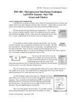
Most horizontal loop installations place flow loops in a parallel
rather than a single (series) loop to reduce pumping power (Figure
23). Parallel loops may require slightly more pipe, but may use
smaller pipe and thus have smaller internal volumes requiring less
antifreeze (if needed). Also, the smaller pipe is typically much
cheaper for a given length, so total pipe cost is less for parallel loops.
An added benefit is that parallel loops can be flushed out with a
smaller purge pump than would be required for a larger single-pipe
loop. A disadvantage of parallel loops is the potential for unequal
flow in the loops and thus reduced heat exchange efficiency.
The time required to install a horizontal loop is not much differ-
ent from that for a vertical system. For the arrangements described
above, a two-person crew can typically install the ground loop for
an average house in a single day.
While not restricted to single-family residential applications,
horizontal loops are rarely used in larger commercial buildings due
to the land area that is required. Even if the land adjacent to the
building were initially available, installation of a horizontal loop
could prevent any future construction above the loop field, tying up
a considerable investment in vacant land. Placement of horizontal
loops under parking lots may have a negative impact on the effec-
tiveness of the ground loop due to the greater surface heat exchange.
Soil characteristics are an important concern for any ground loop
design. With horizontal loops, the soil type can be more easily deter-
mined because the excavated soil can be inspected and tested. EPRI
et al. (1989) compiled a list of criteria and simple test procedures
that can be used to classify soil and rock adequately enough for hor-
izontal ground loop design.
Leaks in the heat-fused plastic pipe are rare when attention is
paid to pipe cleanliness and proper fusion techniques. Should a leak
occur, it is usually best to try to isolate the leaking parallel loop and
abandon it in place. The time and effort required to find the source
of the leak usually far outweighs the cost of replacing the defective
loop. Because the loss of as little as 1 L of water from the system
will cause it to shut down, leaks cannot be located by looking for
wet soil, as is commonly done with water lines.
GROUNDWATER HEAT PUMPS
A groundwater heat pump system (GWHP) removes groundwa-
ter from a well and delivers it to a heat pump (or an intermediate
heat exchanger) to serve as a heat source or sink. Both unitary or
central plant designs are used. In the unitary type, a large number of
small water-to-air heat pumps are distributed throughout the build-
ing. The central plant design uses one or a small number of large-
capacity chillers supplying hot and chilled water to a two- or four-
pipe distribution system.
Regardless of the type of equipment installed in the building, the
specific components for handling the groundwater are similar. The
primary items include (1) the wells (supply and, if required, injec-
tion), (2) well pump, and (3) groundwater heat exchanger. The spe-
cifics of these items are discussed in the section on Direct-Use
Systems. In addition to those comments, the following consider-
ations apply.
Groundwater Flow Requirements
Generally, the greater the groundwater flow, the better the per-
formance (COP or EER) of the heat pumps. However, increasing
heat pump performance can be compromised quickly by well
pump power at high groundwater flow rates. For this reason,
optimum groundwater flow should be based on electrical power
requirements of the well pump, heat pumps, and circulating
pump. Optimum groundwater flow (for minimum system energy
consumption) is a function of groundwater temperature, well
pump pressure, heat exchanger design, loop pump power and
heat pump performance.
For moderate-efficiency heat pumps (COP of 4), efficient loop
pump design (0.016 W/W), and a heat exchanger approach of 1.5
K, Figure 24 provides curves for two different groundwater tem-
peratures (21°C and 10°C) and two well pump pressures (300 and
900 kPa).
Although the four curves show a clear optimum flow, sometimes
operating at a lower groundwater flow reduces the well/pump cap-
ital cost and reduces the problem of fluid disposal. These consider-
ations are highly project specific, but do afford the designer some
latitude in flow selection.
Well Pumps
Submersible pumps have not performed well in higher-tempera-
ture, direct-use projects. However, in a normal groundwater temper-
ature as encountered in heat pump applications, the submersible
pump is a cost-effective option. The low temperature eliminates the
need to specify an industrial design for the motor/protector, thereby
greatly reducing the first cost relative to direct-use. Caution should
still be exercised for wells that are expected to produce moderate
Fig. 23 Parallel and Series Ground Loop Configurations
Geothermal Energy 31.23
2. Chiller capacity is controlled by the heating water (condenser)
loop temperature, and the groundwater flow through the chilled
water exchanger is controlled by chilled water temperature.
For buildings with a significant heating load, the former may be
more attractive, while the latter may be appropriate for conventional
building in moderate-to-warm climates.
SURFACE WATER HEAT PUMPS
Surface water bodies can be very good heat sources and sinks if
properly used. In some cases, lakes can be the very best water sup-
ply for cooling. A variety of water circulation designs are possible
and several of the more common are presented.
In a closed-loop system, a water-to-air heat pump is linked to a
submerged coil. Heat is exchanged to (cooling mode) or from (heat-
ing mode) the lake by the fluid (usually a water-antifreeze mixture)
circulating inside the coil. The heat pump transfers heat to or from
the air in the building.
In an open-loop system, water is pumped from the lake through
a heat exchanger and returned to the lake some distance from the
point at which it was removed. The pump can be located either
slightly above or submerged below the lake water level. For heat
pump operation in the heating mode, this type is restricted to
warmer climates; water temperature must remain above at least
5.5°C.
Thermal stratification of water often keeps large quantities of
cold water undisturbed near the bottom of deep lakes. This water is
cold enough to adequately cool buildings by simply being circulated
through heat exchangers. A heat pump is not needed for cooling,
and energy use is substantially reduced. Closed-loop coils may also
be used in colder lakes. Heating can be provided by a separate
source or with heat pumps in the heating mode. Precooling or
supplemental total cooling are also permitted when water tempera-
ture is between 10 and 15°C.
Heat Transfer in Lakes
Heat is transferred to lakes by three primary modes: radiant
energy from the sun, convective heat transfer from the surrounding
air (when the air temperature is greater than the water temperature),
and conduction from the ground. Solar radiation, which can exceed
950 W per square metre of lake area, is the dominant heating mech-
anism, but it occurs primarily in the upper portion of the lake unless
the lake is very clear. About 40% of the solar radiation is absorbed at
the surface (Pezent and Kavanaugh 1990). Approximately 93% of
the remaining energy is absorbed at depths visible to the human eye.
Convection transfers heat to the lake when the lake surface tem-
perature is lower than the air temperature. Wind speed increases the
rate at which heat is transferred to the lake, but maximum heat gain
by convection is usually only 10 to 20% of maximum solar heat
gain. The conduction gain from the ground is even less than convec-
tion gain (Pezent and Kavanaugh 1990).
Cooling of lakes is accomplished primarily by evaporative heat
transfer at the surface. Convective cooling or heating in warmer
months will contribute only a small percentage of the total because
of the relatively small temperature difference between the air and
the lake surface temperature. Back radiation typically occurs at
night when the sky is clear, and can account for significant amount
of cooling. The relatively warm water surface will radiate heat to the
cooler sky. For example, on a clear night, a cooling rate of up to 160
W/m
2
from a lake 14 K warmer than the sky. The last major mode
of heat transfer, conduction to the ground, does not play a major role
in lake cooling (Pezent and Kavanaugh 1990).
To put these heat transfer rates in perspective, consider a 4000
m
2
lake that is used in connection with a 35 kW heat pump. In the
cooling mode, the unit will reject approximately 44 kW to the lake.
This is 11 W/m
2
, or approximately 1% of the maximum heat gain
from solar radiation in the summer. In the winter, a 35 kW heat
pump would absorb only about 26 kW, or 6.5 W/m
2
, from the lake.
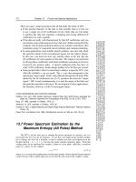
Thermal Patterns in Lakes
The maximum density of water occurs at 4.0°C, not at the freezing
point of 0°C. This phenomenon, in combination with the normal
modes of heat transfer to and from lakes, produces temperature pro-
files advantageous to efficient heat pump operation. In the winter, the
coldest water is at the surface. It tends to remain at the surface and
freeze. The bottom of a deep lake stays 3 to 5 K warmer than the sur-
face. This condition is referred to as winter stagnation. The warmer
water is a better heat source than the colder water at the surface.
Fig. 25 Central Plant Groundwater Systems
31.24 1999 ASHRAE Applications Handbook (SI)
As spring approaches, surface water warms until the temperature
approaches the maximum density point of 4.0°C. The winter strati-
fication becomes unstable and circulation loops begin to develop
from top to bottom. This condition of spring overturn (Peirce 1964)
causes the lake temperature to become fairly uniform.
Later in the spring as the water temperatures rise above 7°C, the
circulation loops are in the upper portion of the lake. This pattern
continues throughout the summer. The upper portion of the lake
remains relatively warm, with evaporation cooling the lake and
solar radiation warming it. The lower portion (hypolimnion) of the
lake remains cold because most radiation is absorbed in the upper
zone. Circulation loops do not penetrate to the lower zone and con-
duction to the ground is quite small. The result is that in deeper lakes
with small or medium inflows, the upper zone is 21 to 32°C, the
lower zone is 4 to 13°C, and the intermediate zone (thermocline) has
a sharp change in temperature within a small change in depth. This
condition is referred to as summer stagnation.
As fall begins, the water surface begins to cool by radiation and
evaporation. With the approach of winter, the upper portion begins
to cool towards the freezing point and the lower levels approach the
maximum density temperature of 4.0°C. An ideal temperature ver-
sus depth chart is shown in Figure 26 for each of the four seasons
(Peirce 1964).
Many lakes do exhibit near-ideal temperature profiles. However, a
variety of circumstances can disrupt the profile. These characteristics
include (1) high inflow/outflow rates, (2) insufficient depth for strat-
ification, (3) level fluctuation, (4) wind, and (5) lack of enough cold
weather to establish sufficient amounts of cold water necessary for
summer stratification. Therefore, a thermal survey of the lake should
be conducted or existing surveys of similar lakes in similar geo-
graphic locations should be consulted.
Closed-Loop Lake Water Heat Pump
The closed-loop lake water heat pump shown in Figure 17 has
several advantages over the open-loop. One advantage is the
reduced fouling resulting from the circulation of clean water (or
water-antifreeze solution) through the heat pump. A second advan-
tage is the reduced pumping power requirement. This results from
the absence of an elevation head from the lake surface to the heat
pumps. A third advantage of a closed-loop is that it is the only type
recommended if a lake temperature below 4°C is possible. The out-
let temperature of the fluid will be about 3 K below that of the inlet
at a flow of 54 mL/s per kilowatt. Frosting will occur on the heat
exchanger surfaces when the bulk water temperature is in the 1 to
3°C range.
A closed-loop system has several disadvantages. Performance of
the heat pump lowers slightly because the circulation fluid temper-
ature drops 2 to 7 K below the lake temperature. A second disadvan-
tage is the possibility of damage to coils located in public lakes.
Thermally fused polyethylene loops are much more resistant to
damage than copper, glued plastic (PVC), or tubing with band-
clamped joints. The third possible disadvantage is fouling on the
outside of the lake coil—particularly in murky lakes or where coils
are located on or near the lake bottom.
Polyethylene (PE 3408) is recommended for all intake piping.
All connections must be either thermally socket fused or butt fused.
These plastic pipes should also have protection from UV radiation,
especially when near the surface. Polyvinyl chloride (PVC) pipe
and plastic pipe with band-clamped joints is not recommended.
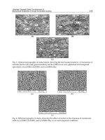
The piping networks of closed-loop systems resemble those
used in ground-coupled heat pump systems. Both a large-diameter
header between the heat pump and lake coil and several parallel
loops of piping in the lake are required. The loops are spread out to
limit thermal interference, hot spots, and cold pockets. While this
Fig. 26 Idealized Diagram of Annual Cycle of
Thermal Stratification in Lakes
Fig. 27 Closed Loop Lake Coil in Bundles
(Kavanaugh 1991)
Geothermal Energy 31.25
layout is preferred in terms of performance, installation is more
time consuming. Many contractors simply unbind plastic pipe coils
and submerged them in a loose bundle. Some compensation for
thermal interference is obtained by making the bundled coils longer
than the spread coils. A diagram of this type of installation is shown
in Figure 27.
Copper coils have also been used successfully. Copper tubes
have a very high thermal conductivity, so coils only one-fourth to
one-third the length of plastic coils are required. However, copper
pipe does not have the durability of PE 3408 or polybutylene, and if
the possibility of fouling exists, coils must be significantly longer.
Antifreeze Requirements
Closed loop horizontal and surface water heat exchanger sys-
tems will often require an antifreeze be added to the circulating
water in locations with significant heating seasons. Antifreeze may
not be needed in a comparable vertical borehole heat exchanger
since the deep ground temperature will be essentially constant. At a
depth of 2 m, a typical value for horizontal heat exchangers, the
ground temperature varies by approximately ±5 K. Even if the mean
ground temperature were 15°C in late winter, the natural ground
temperature would drop to 10°C. The heat extraction process would
lower the temperature even further around the heat exchanger pipes,
probably by an additional 5 K or more. Even with good heat transfer
to the circulating water, the entering water temperature (leaving the
ground heat exchanger) would be around 5°C. Lakes which freeze
at the surface in the winter approach 4°C at the bottom, yielding
nearly the same margin of safety against freezing of the circulating
fluid. An additional 5 K temperature difference is usually needed in
the heat pump’s refrigerant-to-water heat exchanger to transfer the
heat to the refrigerant. Having a refrigerant-to-water coil surface
temperature below the freezing point of water risks the possibility of
growing a layer of ice on the water side of the heat exchanger. In the
best case, icing of the coil would restrict and may eventually block
the flow of water and cause a shutdown. In the worst case, the ice
could burst the tubing in the coil and require a major service
expense.
Several factors must be considered when selecting an antifreeze
for a ground loop heat exchanger. The most important consider-
ations are: (1) impact on system life cycle cost, (2) corrosivity, (3)
leakage, (4) health risks, (5) fire risks, (6) environmental risks from
spills or disposal, and (7) risk of future use (will the antifreeze be
acceptable over the life of the system). A study by Heinonen et al.
(1997) of six antifreezes against these seven criteria is summarized
in Table 9. No single material satisfies all criteria. Methanol and eth-
anol have good viscosity characteristics at low temperatures, yield-
ing lower than average pumping power requirements. However,
they both pose a significant fire hazard when in concentrated forms.
Methanol is also toxic, eliminating it from consideration in areas
that require non-toxic antifreeze to be used. Propylene glycol had no
major concerns, with only leakage and pumping power require-
ments prompting minor concerns. Potassium acetate, calcium mag-
nesium acetate (CMA), and urea have favorable environmental and
safety performance; but they are all subject to significant leakage
problems, which has limited their use in the past.
REFERENCES
Anderson, K.E. 1984. Water well handbook, Missouri Water Well and Pump
Contractors Association, Belle, MD.
Austin, J.C. 1978. A low temperature geothermal space heating demonstra-
tion project. Geothermal Resources Council Transactions 2(2).
Bullard, E. 1973. Basic theories (Geothermal energy; Review of research
and development). UNESCO, Paris.
Caneta Research. 1995. Commercial/institutional ground-source heat pump
engineering manual. ASHRAE, Atlanta.
CSA. 1993. Design and construction of earth energy heat pump systems for
commercial and institutional buildings. Standard C447-93. Canadian
Standards Association, Rexdale, ON.
Campbell, M.D. and J.H. Lehr. 1973. Water well technology. McGraw-Hill,
New York.
Carslaw, H.S. and J.C. Jaeger. 1947. Heat conduction in solids. Claremore
Press, Oxford.
Chandler, R.V. 1987. Alabama streams, lakes, springs and ground waters for
use in heating and cooling. Bulletin 129. Geological Survey of Alabama,
Tuscaloosa, AL.
Christen, J.E. 1977. Central cooling—Absorption chillers. Oak Ridge
National Laboratories, Oak Ridge, TN.
Combs, J., J.K. Applegate, R.O. Fournier, C.A. Swanberg, and D. Nielson.
1980. Exploration, confirmation and evaluation of the resource. In Spe-
cial Report No. 7, Direct utilization of geothermal energy: Technical
handbook. Geothermal Resources Council.
Cosner, S.R. and J.A. Apps. 1978. A compilation of data on fluids from geo-
thermal resources in the United States. DOE Report LBL-5936.
Lawrence Berkeley Laboratory, Berkeley, CA.
Table 9 Suitability of Selected GCHP Antifreeze Solutions
Category Methanol Ethanol
Propy-
lene
Glycol
Potas-
sium
Acetate CMA Urea
Life cycle cost *** *** **
1
**
1
**
1
***
Corrosion **
2
**
3
*** ** **
4
*
5
Leakage *** **
6
**
6
*
7
*
8
*
9
Health hazard risk *
10,11
**
10,12
***
10
***
10
***
10
***
10
Fire risk *
13
*
13
***
14
*** *** ***
Environmental risk **
15
**
15
*** **
15
**
15
***
Risk of future use *
16
**
17
*** **
18
**
19
**
19
Key: * Potential problems, caution in use required
** Minor potential for problems
*** Little or no potential for problems
Category Notes
Life cycle cost 1. Higher than average installation and energy
costs.
Corrosion 2. High black iron and cast iron corrosion rates.
3. High black iron and cast iron, copper and
copper alloy corrosion rates.
4. Medium black iron, copper and copper alloy
corrosion rates.
5. Medium black iron, high cast iron, and
extremely high copper and copper alloy
corrosion rates.
Leakage 6. Minor leakage observed.
7. Moderate leakage observed. Extensive leakage
reported in installed systems.
8. Moderate leakage observed.
9. Massive leakage observed.
Health risk 10. Protective measures required with use. See
MSDS.
11. Prolonged exposure can cause headaches, nau-
sea, vomiting, dizziness, blindness, liver dam-
age, and death. Use of proper equipment and
procedures reduces risk significantly.
12. Confirmed human carcinogen.
Fire Risk 13. Pure fluid only. Little risk when diluted with
water in antifreeze.
14. Very minor potential for pure fluid fire at ele-
vated temperatures.
Environmental risk 15. Water pollution risk.
Risk of future use 16. Toxicity and fire concerns. Prohibited in some
locations.
17. Toxicity, fire and environmental concerns.
18. Potential leakage concerns.
19. Not currently used as GSHP antifreeze
solution. May be difficult to obtain approval
for use.
Source: Heinonen and Tapscott (1996)
31.26 1999 ASHRAE Applications Handbook (SI)
Culver, G.G. and G.M. Reistad. 1978. Evaluation and design of downhole
heat exchangers for direct applications. DOE Report No. RLO-2429-7.
Di Pippo, R. 1988. Industrial developments in geothermal power produc-
tion. Geothermal Resources Council Bulletin 17(5).
Efrid, K.D. and G.E. Moeller. 1978 Electrochemical characteristics of 304
and 316 stainless steels in fresh water as functions of chloride concentra-
tion and temperature. Paper 87, Corrosion/78, Houston, TX.
EPRI. 1989. Soil and rock classification for the design of ground-coupled
heat pump systems. International Ground Source Heat Pump Associa-
tion, Stillwater, OK. Electric Power Research Institute, National Rural
Electric Cooperative Association, Oklahoma State University.
Ellis, P. 1989. Materials selection guidelines. Geothermal Direct Use Engi-
neering and Design Guidebook Ch. 8. Oregon Institute of Technology,
Geo-Heat Center, Klamath Falls, OR.
Ellis, P. and C. Smith. 1983. Addendum to material selection guidelines for
geothermal energy utilization systems. Radian Corporation, Austin, TX.
Ellis, P.F. and M.F. Conover. 1981. Material selection guidelines for geother-
mal energy utilization systems. DOE Report RA/27026-1, Radian Cor-
poration, Austin, TX.
EPA. 1975. Manual of water well construction practices. EPA-570/9-75-
001. U.S. Environmental Protection Agency, Washington, D.C.
Eskilson, P. 1987. Thermal analysis of heat extraction boreholes. University
of Lund, Sweden.
Gudmundsson, J.S. 1985. Direct uses of geothermal energy in 1984. Geo-
thermal Resources Council Proceedings, 1985 International Symposium
on Geothermal Energy, International Volume, Davis, CA.
Hackett, G. and J. H. Lehr. 1985. Iron bacteria occurrence problems and
control methods in water wells. National Water Well Association, Wor-
thington, OH.
Heinonen, E.W. And R.E. Tapscott. 1996. Assessment of anti-freeze solu-
tions for ground-source heat pump systems. New Mexico Engineering
Research Institute for ASHRAE RP-863. ASHRAE.
Heinonen, E.W., R.E. Tapscott, M.W. Wildin, and A.N. Beall. 1997. Assess-
ment of anti-freeze solutions for ground-source heat pump systems.
ASHRAE Research Report 90BRP.
Ingersoll, L.R. and A.C. Zobel. 1954. Heat conduction with engineering and
geological application, 2nd ed. McGraw-Hill, New York.
Interagency Geothermal Coordinating Council. Geothermal energy,
research, development and demonstration program. DOE Report RA-
0050, IGCC-5. U.S. Department of Energy, Washington, D.C.
Kavanaugh, S.P. 1985. Simulation and experimental verification of a verti-
cal ground-coupled heat pump system. Ph.D. thesis. Oklahoma State
University, Stillwater, OK.
Kavanaugh, S.P. 1991. Ground and water source heat pumps. Oklahoma
State University, Stillwater, OK.
Kavanaugh, S.P. 1992. Ground-coupled heat pumps for commercial build-
ing. ASHRAE Journal 34(9):30-37.
Kavanaugh, S.P. and M.C. Pezent. 1990. Lake water applications of water-
to-air heat pumps. ASHRAE Transactions 96(1):813-20.
Kavanaugh, S.P. and K. Rafferty. 1997. Ground-source heat pumps—
Design of geothermal systems for commercial and institutional build-
ings. ASHRAE, Atlanta.
Kindle, C.H. and E.M. Woodruff. 1981. Techniques for geothermal liquid
sampling and analysis. Battelle Pacific Northwest Laboratory, Richland,
WA .
Lienau, P.J. 1979. Materials performance study of the OIT geothermal heat-
ing system. Geo-Heat Utilization Center Quarterly Bulletin, Oregon
Institute of Technology, Klamath Falls, OR.
Lienau, P.J., G.G. Culver and J.W. Lund. 1988. Geothermal direct use devel-
opments in the United States. Oregon Institute of Technology, Geo-Heat
Center, Klamath Falls, OR.
Lund, J.W., P.J. Lienau, G.G. Culver and C.H. Higbee, C.V. 1976. Klamath
Falls geothermal heating district. Geothermal Resources Council Trans-
actions 3.
Lunis, B. 1989. Environmental considerations. Geothermal direct use engi-
neering and design guidebook, Ch. 20. Oregon Institute of Technology,
Geo-Heat Center, Klamath Falls, OR.
Mitchell, D.A. 1980. Performance of typical HVAC materials in two geo-
thermal heating systems. ASHRAE Transactions 86(1):763-68.
Muffler, L.J.P., ed. 1979. Assessment of geothermal Resources of the United
States—1978. U.S. Geological Survey Circular No. 790.
Nichols, C.R. 1978. Direct utilization of geothermal energy: DOE’s resource
assessment program. Direct Utilization of Geothermal Energy: A Sym-
posium. Geothermal Resources Council.
OSU. 1988a. Closed-loop/ground-source heat pump systems installation
guide. International Ground Source Heat Pump Association, Oklahoma
State University, Stillwater, OK.
OSU. 1988b. Closed loop ground source heat pump systems. Oklahoma
State University, Stillwater, OK.
Peirce, L.B. 1964. Reservoir temperatures in north central alabama. Geolog-
ical Survey of Alabama Bulletin 8. Tuscaloosa, AL.
Pezent, M.C. and S.P. Kavanaugh. 1990. Development and verification of a
thermal model of lakes used with water-source heat pumps. ASHRAE
Transactions 96(1).
Rafferty, K. 1989a. A materials and equipment review of selected U.S. geo-
thermal district heating systems. Oregon Institute of Technology, Geo-
Heat Center, Klamath Falls, OR.
Rafferty, K. 1989b. Absorption refrigeration. Geothermal direct use engi-
neering and design guidebook, Ch. 14. Oregon Institute of Technology,
Geo-Heat Center, Klamath Falls, OR.
Reistad, G.M., G.G. Culver, and M. Fukuda. 1979. Downhole heat exchang-
ers for geothermal systems: Performance, economics and applicability.
ASHRAE Transactions 85(1):929-39.
Roscoe Moss Company. 1985. The engineers manual for water well design.
Roscoe Moss Company, Los Angeles, CA.
Stiger, S., J. Renner, and G. Culver. 1989. Well testing and reservoir evalu-
ation. Geothermal and direct use engineering and design guidebook, Ch.
7. Oregon Institute of Technology, Geo-Heat Center, Klamath Falls, OR.
Svec, O. J. 1990. Spiral ground heat exchangers for heat pump applications.
Proceedings of 3rd IEA Heat Pump Conference. Pergamon Press, Tokyo.
UOP. 1975. Ground water and wells. Johnson Division, UOP Inc., St. Paul,
MN.
BIBLIOGRAPHY
Allen, E. 1980. Preliminary inventory of western U.S. cities with proximate
hydrothermal potential. Eliot Allen and Associates, Salem, OR.
Anderson, D.A. and J.W. Lund, eds. 1980. Direct utilization of geothermal
energy: Technical handbook. Geothermal Resources Council Special
Report No. 7.
Caneta Research. 1995. Operating experiences with commercial ground-
source heat pumps. ASHRAE Research Project 863.
CHAPTER 32
SOLAR ENERGY USE
Quality and Quantity of Solar Energy 32.1
Solar Energy Collection 32.6
Heat Storage 32.11
Water Heating 32.11
Components 32.14
Cooling by Solar Energy 32.16
Cooling by Nocturnal Radiation and Evaporation 32.16
Solar Heating and Cooling Systems 32.17
Sizing Solar Heating and Cooling Systems—
Energy Requirements 32.19
Installation Guidelines 32.23
Design, Installation, and Operation
Checklist 32.25
Photovoltaic Applications 32.26
HE major obstacles encountered in solar heating and cooling
Tare economic—the equipment needed to collect and store solar
energy is high in cost. In some cases, the cost of the solar equipment
is greater than the resulting savings in fuel costs. Some of the prob-
lems inherent in the nature of solar radiation include:
• It is relatively low in intensity, rarely exceeding 950 W/m
2
. Con-
sequently, when large amounts of energy are needed, large collec-
tors must be used.
• It is intermittent because of the variation in solar radiation inten-
sity from zero at sunrise to a maximum at noon and back to zero
at sunset. Some means of energy storage must be provided at
night and during periods of low solar radiation.
• It is subject to unpredictable interruptions because of clouds, rain,
snow, hail, or dust.
Systems should make maximum use of the solar energy input by
effectively using the energy at the lowest temperatures possible.
QUALITY AND QUANTITY OF SOLAR ENERGY
Solar Constant
Solar energy approaches the earth as electromagnetic radiation,
with wavelengths ranging from 0.1 µm (X rays) to 100 m (radio
waves). The earth maintains a thermal equilibrium between the
annual input of shortwave radiation (0.3 to 2.0 µm) from the sun and
the outward flux of longwave radiation (3.0 to 30 µm). Only a lim-
ited band need be considered in terrestrial applications, because
99% of the sun’s radiant energy has wavelengths between 0.28 and
4.96 µm. The current value of the solar constant (which is defined
as the intensity of solar radiation on a surface normal to the sun’s
rays, just beyond the earth’s atmosphere at the average earth-sun
distance) is 1367 W/m
2
. The section on Determining Incident Solar
Flux in Chapter 29 of the 1997 ASHRAE Handbook—Fundamentals
has further information on this topic.
Solar Angles
The axis about which the earth rotates is tilted at an angle of
23.45° to the plane of the earth’s orbital plane and the sun’s equator.
The earth’s tilted axis results in a day-by-day variation of the angle
between the earth-sun line and the earth’s equatorial plane, called
the solar declination δ. This angle varies with the date, as shown in
Table 1 for the year 1964 and in Table 2 for 1977. For other dates, the
declination may be estimated by the following equation:
(1)
where N = year day, with January 1 = 1. For values of N, see Tables
1 and 2.
The relationship between δ and the date varies to an insignificant
degree. The daily change in the declination is the primary reason for
the changing seasons, with their variation in the distribution of solar
radiation over the earth’s surface and the varying number of hours of
daylight and darkness.
The earth’s rotation causes the sun’s apparent motion (Figure 1).
The position of the sun can be defined in terms of its altitude β
above the horizon (angle HOQ) and its azimuth φ, measured as
angle HOS in the horizontal plane.
At solar noon, the sun is exactly on the meridian, which contains
the south-north line. Consequently, the solar azimuth φ is 0°. The
noon altitude β
N
is given by the following equation as
(2)
where LAT = latitude.
Because the earth’s daily rotation and its annual orbit around the
sun are regular and predictable, the solar altitude and azimuth may
be readily calculated for any desired time of day when the latitude,
longitude, and date (declination) are specified. Apparent solar time
(AST) must be used, expressed in terms of the hour angle H, where
(3)
Solar Time
Apparent solar time (AST) generally differs from local standard
time (LST) or daylight saving time (DST), and the difference can be
significant, particularly when DST is in effect. Because the sun
The preparation of this chapter is assigned to TC 6.7, Solar Energy Utiliza-
tion.
δ 23.45 sin 360° 284 N+()365⁄[]=
Fig. 1 Apparent Daily Path of the Sun Showing Solar
Altitude (β) and Solar Azimuth (φ)
β
N
90° LAT δ+–=
H number of hours from solar noon()15°×=
number of minutes from solar noon()4⁄=
Solar Energy Use 32.3
To determine θ, the surface azimuth ψ and the surface-solar
azimuth γ must be known. The surface azimuth (angle POS in Fig-
ure 2) is the angle between the south-north line SO and the normal
PO to the intersection of the irradiated surface with the horizontal
plane, shown as line OM. The surface-solar azimuth, angle HOP, is
designated by γ and is the angular difference between the solar
azimuth φ and the surface azimuth ψ. For surfaces facing east of
south, γ = φ − ψ in the morning and γ = φ + ψ in the afternoon. For
surfaces facing west of south, γ = φ + ψ in the morning and γ = φ −
ψ in the afternoon. For south-facing surfaces, ψ = 0°, so γ = φ for all
conditions. The angles δ, β, and φ are always positive.
For a surface with a tilt angle Σ (measured from the horizontal),
the angle of incidence θ between the direct solar beam and the nor-
mal to the surface (angle QOP ′ in Figure 2) is given by:
(8)
For vertical surfaces, Σ = 90°, cos Σ = 0, and sin Σ = 1.0, so Equa-
tion (8) becomes
(9)
For horizontal surfaces, Σ = 0°, sin Σ = 0, and cos Σ = 1.0, so
Equation (8) leads to
(10)
Example 2. Find θ for a south-facing surface tilted upward 30° from the
horizontal at 40° north latitude at 4:00 P.M., AST, on August 21.
Solution: From Equation (3), at 4:00 P.M.
on August 21,
From Table 1,
From Equation (5),
From Equation (6),
The surface faces south, so
φ = γ. From Equation (8),
ASHRAE Standard 93, Methods of Testing to Determine the
Thermal Performance of Solar Collectors, provides tabulated values
of q for horizontal and vertical surfaces and for south-facing sur-
faces tilted upward at angles equal to the latitude minus 10°, the lat-
itude, the latitude plus 10°, and the latitude plus 20°. These tables
cover the latitudes from 24° to 64° north, in 8° intervals.
Solar Spectrum
Beyond the earth’s atmosphere, the effective black body temper-
ature of the sun is 5760 K. The maximum spectral intensity occurs
at 0.48 µm in the green portion of the visible spectrum (Figure 3).
Thekaekara (1973) presents tables and charts of the sun’s extrater-
restrial spectral irradiance from 0.120 to 100 µm, the range in which
most of the sun’s radiant energy is contained. The ultraviolet portion
of the spectrum below 0.40 µm contains 8.73% of the total, another
38.15% is contained in the visible region between 0.40 and 0.70 µm,
and the infrared region contains the remaining 53.12%.
Solar Radiation at the Earth’s Surface
In passing through the earth’s atmosphere, some of the sun’s
direct radiation I
D
is scattered by nitrogen, oxygen, and other
molecules, which are small compared to the wavelengths of the
radiation; and by aerosols, water droplets, dust, and other particles
with diameters comparable to the wavelengths (Gates 1966). This
Fig. 2 Solar Angles with Respect to a Tilted Surface
cos θ cos β cos γ sin Σ sin β cos Σ+=
cos θ cos β cos γ=
θ
H
90°β–=
Fig. 3 Spectral Solar Irradiation at Sea Level for Air-Mass = 1.0
H 415
°×
60
°
==
δ
12.1
°
=
sin
β
cos 40° cos 12.1° cos 60° sin 40° sin 12.1°+=
β
30.6°=
sin
φ
cos 12.1° sin 60° cos 30.6°
⁄
=
φ
79.7°=
cos
θ
cos 30.6° cos 79.7° sin 30° sin 30.6° cos 30°+=
θ
58.8°=
32.4 1999 ASHRAE Applications Handbook (SI)
scattered radiation causes the sky to appear blue on clear days, and
some of it reaches the earth as diffuse radiation I.
Attenuation of the solar rays is also caused by absorption, first by
the ozone in the outer atmosphere, which causes a sharp cutoff at
0.29 µm of the ultraviolet radiation reaching the earth’s surface. In
the longer wavelengths, there are a series of absorption bands caused
by water vapor, carbon dioxide, and ozone. The total amount of
attenuation at any given location is determined by (1) the length of
the atmospheric path through which the rays traverse and (2) the
composition of the atmosphere. The path length is expressed in terms
of the air mass m, which is the ratio of the mass of atmosphere in the
actual earth-sun path to the mass that would exist if the sun were
directly overhead at sea level (m = 1.0). For all practical purposes, at
sea level, m = 1.0/sin β. Beyond the earth’s atmosphere, m = 0.
Prior to 1967, solar radiation data was based on an assumed
solar constant of 1324 W/m
2
and on a standard sea level atmosphere
containing the equivalent depth of 2.8 mm of ozone, 20 mm of pre-
cipitable moisture, and 300 dust particles per cubic centimeter.
Threlkeld and Jordan (1958) considered the wide variation of water
vapor in the atmosphere above the United States at any given time,
and particularly the seasonal variation, which finds three times as
much moisture in the atmosphere in midsummer as in December,
January, and February. The basic atmosphere was assumed to be at
sea level barometric pressure, with 2.5 mm of ozone, 200 dust
particles per cm
3
, and an actual precipitable moisture content that
varied throughout the year from 8 mm in midwinter to 28 mm in
mid-July. Figure 4 shows the variation of the direct normal irradi-
ation with solar altitude, as estimated for clear atmospheres and for
an atmosphere with variable moisture content.
Stephenson (1967) showed that the intensity of the direct normal
irradiation I
DN
at the earth’s surface on a clear day can be estimated
by the following equation:
(11)
where A, the apparent extraterrestrial irradiation at m = 0, and B, the
atmospheric extinction coefficient, are functions of the date and take
into account the seasonal variation of the earth-sun distance and the
air’s water vapor content.
The values of the parameters A and B given in Table 1 were
selected so that the resulting value of I
DN
would be in close agree-
ment with the Threlkeld and Jordan (1958) values on average cloud-
less days. The values of I
DN
given in Tables 15 through 21 in
Chapter 29 of the 1997 ASHRAE Handbook—Fundamentals, were
obtained by using Equation (11) and data from Table 1. The values
of the solar altitude β and the solar azimuth φ may be obtained from
Equations (5) and (6).
Because local values of atmospheric water content and elevation
can vary markedly from the sea level average, the concept of clear-
ness number was introduced to express the ratio between the actual
clear-day direct irradiation intensity at a specific location and the
intensity calculated for the standard atmosphere for the same loca-
tion and date.
Figure 5 shows the Threlkeld-Jordan map of winter and summer
clearness numbers for the continental United States. Irradiation val-
ues should be adjusted by the clearness numbers applicable to each
particular location.
Design Values of Total Solar Irradiation
The total solar irradiation I
tθ
of a terrestrial surface of any orien-
tation and tilt with an incident angle θ is the sum of the direct com-
ponent I
DN
cos θ plus the diffuse component I
dθ
coming from the
sky plus whatever amount of reflected shortwave radiation I
r
may
reach the surface from the earth or from adjacent surfaces:
(12)
The diffuse component is difficult to estimate because of its non-
directional nature and its wide variations. Figure 4 shows typical
values of diffuse irradiation of horizontal and vertical surfaces. For
clear days, Threlkeld (1963) has derived a dimensionless parameter
(designated as C in Table 1), which depends on the dust and mois-
ture content of the atmosphere and thus varies throughout the year:
(13)
where I
dH
is the diffuse radiation falling on a horizontal surface
under a cloudless sky.
Fig. 4 Variation with Solar Altitude and Time of Year for
Direct Normal Irradiation
I
DN
Ae
B–
β
sin
⁄
=
Fig. 5 Clearness Numbers for the United States
I
t
θ
I
DN
cos θ I
d
θ
I
r
++=
CI
dH
I
DN
⁄=
Solar Energy Use 32.5
The following equation may be used to estimate the amount of
diffuse radiation I
dθ
that reaches a tilted or vertical surface:
(14)
where
(15)
The reflected radiation I
r
from the foreground is given by the fol-
lowing equation:
(16)
where
ρ
g
= reflectance of the foreground
I
tH
= total horizontal irradiation
(17)
The intensity of the reflected radiation that reaches any surface
depends on the nature of the reflecting surface and on the incident
angle between the sun’s direct beam and the reflecting surface.
Many measurements made of the reflection (albedo) of the earth
under varying conditions show that clean, fresh snow has the high-
est reflectance (0.87) of any natural surface.
Threlkeld (1963) gives values of reflectance for commonly
encountered surfaces at solar incident angles from 0 to 70°. Bitumi-
nous paving generally reflects less than 10% of the total incident
solar irradiation; bituminous and gravel roofs reflect from 12 to
15%; concrete, depending on its age, reflects from 21 to 33%.
Bright green grass reflects 20% at θ = 30° and 30% at θ = 65°.
The maximum daily amount of solar irradiation that can be
received at any given location is that which falls on a flat plate with
its surface kept normal to the sun’s rays so it receives both direct and
diffuse radiation. For fixed flat-plate collectors, the total amount of
clear day irradiation depends on the orientation and slope. As shown
by Figure 6 for 40° north latitude, the total irradiation of horizontal
surfaces reaches its maximum in midsummer, while vertical south-
facing surfaces experience their maximum irradiation during the
winter. These curves show the combined effects of the varying
length of days and changing solar altitudes.
In general, flat-plate collectors are mounted at a fixed tilt angle
Σ (above the horizontal) to give the optimum amount of irradiation for
each purpose. Collectors intended for winter heating benefit from
higher tilt angles than those used to operate cooling systems in summer.
Solar water heaters, which should operate satisfactorily throughout the
year, require an angle that is a compromise between the optimal values
for summer and winter. Figure 6 shows the monthly variation of total
day-long irradiation on the 21st day of each month at 40° north latitude
for flat surfaces with various tilt angles.
Tables in ASHRAE Standard 93 give the total solar irradiation
for the 21st day of each month at latitudes 24° to 64° north on sur-
faces with the following orientations: normal to the sun’s rays
(direct normal data do not include diffuse irradiation); horizontal;
south-facing, tilted at (LAT−10), LAT, (LAT+10), (LAT+20), and
90° from the horizontal. The day-long total irradiation for fixed sur-
faces is highest for those that face south, but a deviation in azimuth
of 15° to 20° causes only a small reduction.
Solar Energy for Flat-Plate Collectors
The preceding data apply to clear days. The irradiation for
average days may be estimated for any specific location by referring
to publications of the U.S. Weather Service. The Climatic Atlas of
the United States (U.S. GPO 1968) gives maps of monthly and an-
nual values of percentage of possible sunshine, total hours of sun-
shine, mean solar radiation, mean sky cover, wind speed, and wind
direction.
The total daily horizontal irradiation data reported by the U.S.
Weather Bureau for approximately 100 stations prior to 1964 show
that the percentage of total clear-day irradiation is approximately a
linear function of the percentage of possible sunshine. The irradia-
tion is not zero for days when the percentage of possible sunshine is
reported as zero, because substantial amounts of energy reach the
earth in the form of diffuse radiation. Instead, the following rela-
tionship exists:
(18)
where a and b are constants for any specified month at any given
location. See also Jordan and Liu (1977) and Duffie and Beckman
(1974).
Longwave Atmospheric Radiation
In addition to the shortwave (0.3 to 2.0 µm) radiation it receives
from the sun, the earth receives longwave radiation (4 to 100 µm,
with maximum intensity near 10 µm) from the atmosphere. In turn,
a surface on the earth emits longwave radiation q
Rs
in accordance
with the Stefan-Boltzmann law:
(19)
where
e
s
= surface emittance
σ = Stefan-Boltzmann constant, 5.67 × 10
−8
W/(m
2
⋅Κ
4
)
T
s
= absolute temperature of the surface, K
For most nonmetallic surfaces, the longwave hemispheric emit-
tance is high, ranging from 0.84 for glass and dry sand to 0.95 for
black built-up roofing. For highly polished metals and certain selec-
tive surfaces, e
s
may be as low as 0.05 to 0.20.
I
d
θ
C I
DN
F
ss
=
F
ss
1cos Σ+()2⁄=
angle factor between the surface and the sky=
I
r
I
tH
ρ
g
F
sg
=
F
sg
1cos Σ–()2⁄=
angle factor between the surface and the earth=
Fig. 6 Total Daily Irradiation for Horizontal, Tilted,
and Vertical Surfaces at 40° North Latitude
Day-long actual I
tH
Clear day I
tH
100 ab+= (% possible sunshine)
q
Rs
e
s
σT
s
4
=
Solar Energy Use 32.7
A flat-plate collector generally consists of the following compo-
nents (see Figure 8):
• Glazing. One or more sheets of glass or other diathermanous
(radiation-transmitting) material.
• Tubes, fins, or passages. To conduct or direct the heat transfer
fluid from the inlet to the outlet.
• Absorber plates. Flat, corrugated, or grooved plates, to which the
tubes, fins, or passages are attached. The plate may be integral
with the tubes.
• Headers or manifolds. To admit and discharge the fluid.
• Insulation. To minimize heat loss from the back and sides of the
collector.
• Container or casing. To surround the aforementioned compo-
nents and keep them free from dust, moisture, etc.
Flat-plate collectors have been built in a wide variety of designs
from many different materials (Figure 9). They have been used to heat
fluids such as water, water plus an antifreeze additive, or air. Their
major purpose is to collect as much solar energy as possible at the
lowest possible total cost. The collector should also have a long effec-
tive life, despite the adverse effects of the sun’s ultraviolet radiation;
corrosion or clogging because of acidity, alkalinity, or hardness of the
heat transfer fluid; freezing or air-binding in the case of water, or dep-
osition of dust or moisture in the case of air; and breakage of the glaz-
ing because of thermal expansion, hail, vandalism, or other causes.
These problems can be minimized by the use of tempered glass.
Glazing Materials
Glass has been widely used to glaze flat plate solar collectors
because it can transmit as much as 90% of the incoming shortwave
solar irradiation while transmitting virtually none of the longwave
radiation emitted outward by the absorber plate. Glass with low
iron content has a relatively high transmittance for solar radiation
(approximately 0.85 to 0.90 at normal incidence), but its transmit-
tance is essentially zero for the longwave thermal radiation (5.0 to
50 µm) emitted by sun-heated surfaces.
Plastic films and sheets also possess high shortwave transmit-
tance, but because most usable varieties also have transmission
bands in the middle of the thermal radiation spectrum, they may
have longwave transmittances as high as 0.40.
Plastics are also generally limited in the temperatures they can
sustain without deteriorating or undergoing dimensional changes.
Only a few finds of plastics can withstand the sun’s ultraviolet radi-
ation for long periods. However, they are not broken by hail and
other stones and, in the form of thin films, they are completely flex-
ible and have low mass.
The glass generally used in solar collectors may be either single-
strength (2.2 to 2.5 mm thick) or double-strength (2.9 to 3.4 mm
Fig. 8 Exploded Cross Section Through Double-Glazed
Solar Water Heater
Fig. 9 Various Types of Solar Collectors
32.8 1999 ASHRAE Applications Handbook (SI)
thick). The commercially available grades of window and green-
house glass have normal incidence transmittances of about 0.87 and
0.85, respectively. For direct radiation, the transmittance varies
markedly with the angle of incidence, as shown in Table 4, which
gives transmittances for single- and double-glazing using double-
strength clear window glass.
The 4% reflectance from each glass-air interface is the most
important factor in reducing transmission, although a gain of about
3% in transmittance can be obtained by using water-white glass.
Antireflective coatings and surface texture can also improve trans-
mission significantly. The effect of dirt and dust on collector glazing
may be quite small, and the cleansing effect of an occasional rainfall
is usually adequate to maintain the transmittance within 2 to 4% of
its maximum.
The glazing should admit as much solar irradiation as possible
and reduce the upward loss of heat as much as possible. Although
glass is virtually opaque to the longwave radiation emitted by col-
lector plates, absorption of that radiation causes an increase in the
glass temperature and a loss of heat to the surrounding atmosphere
by radiation and convection. This type of heat loss can be reduced
by using an infrared reflective coating on the underside of the glass;
however, such coatings are expensive and reduce the effective solar
transmittance of the glass by as much as 10%.
In addition to serving as a heat trap by admitting shortwave solar
radiation and retaining longwave thermal radiation, the glazing also
reduces heat loss by convection. The insulating effect of the glazing is
enhanced by the use of several sheets of glass, or glass plus plastic. The
loss from the back of the plate rarely exceeds 10% of the upward loss.
Collector Plates
The collector plate absorbs as much of the irradiation as possible
through the glazing, while losing as little heat as possible upward to
the atmosphere and downward through the back of the casing. The
collector plates transfer the retained heat to the transport fluid. The
absorptance of the collector surface for shortwave solar radiation
depends on the nature and color of the coating and on the incident
angle, as shown in Table 4 for a typical flat black paint.
By suitable electrolytic or chemical treatments, selective sur-
faces can be produced with high values of solar radiation absorp-
tance α and low values of longwave emittance e
s
. Essentially,
typical selective surfaces consist of a thin upper layer, which is
highly absorbent to shortwave solar radiation but relatively trans-
parent to longwave thermal radiation, deposited on a substrate that
has a high reflectance and a low emittance for longwave radiation.
Selective surfaces are particularly important when the collector sur-
face temperature is much higher than the ambient air temperature.
For fluid-heating collectors, passages must be integral with or
firmly bonded to the absorber plate. A major problem is obtaining a
good thermal bond between tubes and absorber plates without
incurring excessive costs for labor or materials. Materials most fre-
quently used for collector plates are copper, aluminum, and steel.
UV-resistant plastic extrusions are used for low-temperature appli-
cation. If the entire collector area is in contact with the heat transfer
fluid, the thermal conductance of the material is not important.
Whillier (1964) concluded that steel tubes are as effective as cop-
per if the bond conductance between tube and plate is good. Poten-
tial corrosion problems should be considered for any metals. Bond
conductance can range from a high of 5700 W/(m
2
·K) for a securely
soldered or brazed tube to a low of 17 W/(m
2
·K) for a poorly
clamped or badly soldered tube. Plates of copper, aluminum, or
stainless steel with integral tubes are among the most effective types
available. Figure 9 shows a few of the solar water and air heaters that
have been used with varying degrees of success.
Concentrating Collectors
Temperatures far above those attainable by flat-plate collectors
can be reached if a large amount of solar radiation is concentrated on
a relatively small collection area. Simple reflectors can markedly
increase the amount of direct radiation reaching a collector, as
shown in Figure 10A.
Because of the apparent movement of the sun across the sky,
conventional concentrating collectors must follow the sun’s daily
motion. There are two methods by which the sun’s motion can be
readily tracked. The altazimuth method requires the tracking device
to turn in both altitude and azimuth; when performed properly, this
method enables the concentrator to follow the sun exactly. Parabo-
loidal solar furnaces, Figure 10B, generally use this system. The
polar, or equatorial, mounting points the axis of rotation at the North
Star, tilted upward at the angle of the local latitude. By rotating the
collector 15° per hour, it follows the sun perfectly (on March 21 and
September 21). If the collector surface or aperture must be kept nor-
mal to the solar rays, a second motion is needed to correct for the
change in the solar declination. This motion is not essential for most
solar collectors.
The maximum variation in the angle of incidence for a collector
on a polar mount will be ±23.5° on June 21 and December 21; the
incident angle correction would then be cos 23.5° = 0.917.
Horizontal reflective parabolic troughs, oriented east and west,
as shown in Figure 10C, require continuous adjustment to compen-
sate for the changes in the sun’s declination. There is inevitably
some morning and afternoon shading of the reflecting surface if the
concentrator has opaque end panels. The necessity of moving the
concentrator to accommodate the changing solar declination can be
reduced by moving the absorber or by using a trough with two sec-
tions of a parabola facing each other, as shown in Figure 10D.
Known as a compound parabolic concentrator (CPC), this design
can accept incoming radiation over a relatively wide range of an-
gles. By using multiple internal reflections, any radiation that is ac-
cepted finds its way to the absorber surface located at the bottom of
the apparatus. By filling the collector shape with a highly transpar-
ent material having an index of refraction greater than 1.4, the ac-
ceptance angle can be increased. By shaping the surfaces of the
array properly, total internal reflection is made to occur at the me-
dium-air interfaces, which results in a high concentration efficiency.
Known as a dielectric compound parabolic concentrator
(DCPC), this device has been applied to the photovoltaic generation
of electricity (Cole et al. 1977).
The parabolic trough of Figure 10C can be simulated by many
flat strips, each adjusted at the proper angle so that all reflect onto a
common target. By supporting the strips on ribs with parabolic con-
tours, a relatively efficient concentrator can be produced with less
tooling than the complete reflective trough.
Another concept applied this segmental idea to flat and cylindri-
cal lenses. A modification is shown in Figure 10F, in which a linear
Fresnel lens, curved to shorten its focal distance, can concentrate a
relatively large area of radiation onto an elongated receiver. Using
Table 4 Variation with Incident Angle
of Transmittance for Single and Double Glazing and
Absorptance for Flat Black Paint
Incident
Angle, Deg
Transmittance
Absorptance for
Flat Black PaintSingle Glazing Double Glazing
0 0.87 0.77 0.96
10 0.87 0.77 0.96
20 0.87 0.77 0.96
30 0.87 0.76 0.95
40 0.86 0.75 0.94
50 0.84 0.73 0.92
60 0.79 0.67 0.88
70 0.68 0.53 0.82
80 0.42 0.25 0.67
90 0.00 0.00 0.00
32.10 1999 ASHRAE Applications Handbook (SI)
in Figure 12. Manufacturers of such surfaces should be asked for
values applicable to their products, or test results that give the nec-
essary information should be consulted.
Example 5. A flat-plate collector is operating in Denver, latitude = 40°
north, on July 21 at noon solar time. The atmospheric temperature is
assumed to be 30°C, and the average temperature of the absorber plate
is 60°C. The collector is single-glazed with flat black paint on the
absorber. The collector faces south, and the tilt angle is 30° from the
horizontal. Find the rate of heat collection and the collector efficiency.
Neglect the losses from the back and sides of the collector.
Solution: From Table 2, δ = 20.6°.
From Equation (2),
From Equation (3), H = 0; therefore from Equation (6), sin φ = 0
and thus, φ = 0°. Because the collector faces south, ψ = 0°, and γ = φ.
Thus γ = 0°. Then Equation (8) gives
From Table 1, A = 1085 W/m
2
, B = 0.207, and C = 0.136. Using
Equation (11),
Combining Equations (14) and (15) gives
Assuming I
r
= 0, Equation (12) gives a total solar irradiation on the
collector of
From Figure 11, for n = 1, τ = 0.87 and α = 0.96.
From Figure 12, for an absorber plate temperature of 60°C and an
air temperature of 30°C, U
L
= 7.3 W/(m
2
·K).
Then from Equation (24),
The collector efficiency η is
The general expression for collector efficiency is
(26)
For incident angles below about 35°, the product τ times α is essen-
tially constant and Equation (26) is linear with respect to the param-
eter (t
p
− t
at
)/I
tθ
, as long as U
L
remains constant.
ASHRAE (1977) suggested that an additional term, the collector
heat removal factor F
R
, be introduced to permit the use of the fluid
inlet temperature in Equations (24) and (26):
(27)
(28)
where F
R
equals the ratio of the heat actually delivered by the col-
lector to the heat that would be delivered if the absorber were at t
fi
.
F
R
is found from the results of a test performed in accordance with
ASHRAE Standard 93.
Fig. 11 Variation of Absorptance and Transmittance with
Incident Angle
Fig. 12 Variation of Upward Heat Loss Coefficient U
L
with
Collector Plate Temperature and Ambient Air Temperatures
for Single-, Double-, and Triple-Glazed Collectors
β
N
90
°
40
°
20.6
°
+– 70.6
°
==
cos
θ
cos 70.6° cos 0° sin 30° sin 70.6° cos 30°+=
0.332
()
1
()
MP 0.5
()
0.943
()
0.866
()
+=
0.983=
θ
10.6°=
I
DN
1085 e
0.207– sin 70.6°⁄
871 W m
2
⁄
=
⁄
=
I
tθ
0.136 871 1 cos 30+
()
2 111 W m
2
⁄
=
⁄×
=
I
tθ
871 cos 10.6 111+ 967 W m
2
⁄
==
q
u
967 0.87 0.96
×()
7.3 60 30–
()
589 W m
2
⁄
=–=
589 967
⁄
0.60=
ητα()
θ
U
L
– t
p
t
at
–()I
t
θ
⁄=
q
u
F
R
I
tθ
τα()
θ
U
L
t
fi
t
at
–()–[]=
η F
R
τα()
θ
F
R
U
L
– t
fi
t
at
–()I
tθ
⁄=
32.12 1999 ASHRAE Applications Handbook (SI)
collector to storage. For direct systems, pressure-reducing valves
are required when the city water pressure is greater than the working
pressure of the collectors. In a thermosiphon system, the storage
tank must be elevated above the collectors, which sometimes
requires designing the upper level floor and ceiling joists to bear this
additional load. Extremely hard or acidic water can cause scale
deposits that clog or corrode the absorber fluid passages. Thermo-
siphon flow is induced whenever there is sufficient sunshine, so
these systems do not need pumps.
Direct Circulation Systems
A direct circulation system (Figure 15) pump potable water
from storage to the collectors when there is enough solar energy
available to warm it. They then return the heated water to the
storage tank until it is needed. The collectors can be mounted
either above or below the storage tank. Direct circulation systems
are only feasible in areas where freezing is infrequent. Freeze
protection is provided either by recirculating warm water from
the storage tank or by flushing the collectors with cold water.
Direct water heating systems should not be used in areas where
the water is extremely hard or acidic because scale deposits may
clog or corrode the absorber fluid passages, rendering the system
inoperable.
Direct circulation systems are exposed to city water line pres-
sures and must withstand pressures as required by local codes.
Pressure-reducing valves and pressure relief valves are required
when the city water pressure is greater than the working pressure of
the collectors. Direct circulation systems often use a single storage
tank for both solar energy storage and the auxiliary water heater,
but two-tank storage systems can be used.
Draindown systems. Draindown systems (Figure 16) are direct
circulation, water heating systems in which potable water is
pumped from storage to the collector array where it is heated. Cir-
culation continues until usable solar heat is no longer available.
When a freezing condition is anticipated or a power outage occurs,
the system drains automatically by isolating the collector array and
exterior piping from the city water pressure and using one or more
valves for draining. The solar collectors and associated piping must
be carefully sloped to drain the collector’s exterior piping.
Indirect Water Heating Systems
Indirect water heating systems (Figure 17) circulate a freeze-
protected heat transfer fluid through the closed collector loop to a
heat exchanger, where its heat is transferred to the potable water.
The most commonly used heat transfer fluids are water/ethylene
glycol and water/propylene glycol solutions, although other heat
transfer fluids such as silicone oils, hydrocarbons, and refrigerants
can also be used (ASHRAE 1983). These fluids are nonpotable,
sometimes toxic, and normally require double-wall heat exchang-
ers. The double-wall heat exchanger can be located inside the
Fig. 14 Thermosiphon System
Fig. 15 Direct Circulation System
Fig. 16 Draindown System
Fig. 17 Indirect Water Heating
Solar Energy Use 32.13
storage tank, or an external heat exchanger can be used. The col-
lector loop is closed and therefore requires an expansion tank and
a pressure relief valve. a one- or two-tank storage can be used.
Additional over-temperature protection may be needed to prevent
the collector fluid from decomposing or becoming corrosive.
Designers should avoid automatic water makeup in systems
using water/antifreeze solutions because a significant leak may
raise the freezing temperature of the solution above the ambient
temperature, causing the collector array and exterior piping to
freeze. Also, antifreeze systems with large collector arrays and long
pipe runs may need a time-delayed bypass loop around the heat
exchanger to avoid freezing the heat exchanger on startup.
Drainback Systems. Drainback systems are generally indirect
water heating systems that circulate treated or untreated water
through the closed collector loop to a heat exchanger, where its heat
is transferred to the potable water. Circulation continues until usable
energy is no longer available. When the pump stops, the collector
fluid drains by gravity to a storage or tank. In a pressurized system,
the tank also serves as an expansion tank, so it must have a temper-
ature and pressure relief valve to protect against excessive pressure.
In an unpressurized system (Figure 18), the tank is open and vented
to the atmosphere.
The collector loop is isolated from the potable water, so valves
are not needed to actuate draining, and scaling is not a problem. The
collector array and exterior piping must be sloped to drain com-
pletely, and the pumping pressure must be sufficient to lift water to
the top of the collector array.
Integral Collector-Storage Systems
Integral collector storage (ICS) systems use hot water storage as
part of the collector. Some types use the surface of a single tank as
the absorber, and others use multiple, long, thin tanks placed side-
by-side horizontally to form the absorber surface. In this type of
ICS, hot water is drawn from the top tank and cold replacement
water enters the bottom tank. Because of the greater nighttime heat
loss from ICS systems, they are typically less efficient than
pumped systems, and selective surfaces are recommended. ICS
systems are normally installed as a solar preheater without pumps
or controllers. Flow through the ICS system occurs on demand, as
hot water flows from the collector to a hot water auxiliary tank in
the structure.
Site-Built Systems
Site-built, large volume solar, water, air, or water heating equip-
ment is used in commercial and industrial applications. The site
built systems are based on a transpired solar collector for air heating
and shallow solar pond technologies.
Transpired Solar Collector. This collector preheats outdoor air
by drawing it through small holes in a metal panel. It is typically
installed on south facing walls and is designed to heat outdoor air
for building ventilation or process applications (Kutscher 1996).
The prefabricated panel efficiently heats and captures fresh air by
drawing it through a perforated adsorber, eliminating the cost and
the reflection losses associated with a glazing. The panel consists
of a dark-colored, metal building panel with thousands of small
holes. The sun heats the metal panel that in turn, heats a boundary
layer of air on its surface. Air is heated as it is drawn through the
small holes into a ventilation system for delivery as ventilation air,
crop drying, or other process applications.
Shallow Solar Pond. The shallow solar pond (SSP) is a large-
scale integral collector storage (ICS), solar water heater (Figure 19)
capable of providing more than 19 m
3
of hot water per day for com-
mercial and industrial use. These ponds are built in standard mod-
ules and tied together to supply the required load. The SSP module
can be ground mounted or installed on a roof. It is typically 5 m wide
and up to 60 m long. The module contains one or two flat water bags
similar to a water bed. The bags rest on a layer of insulation inside
concrete or fiberglass curbs. The bag is protected against damage
and heat loss by greenhouse glazing. A typical pond filled to a
100 mm depth holds approximately 23 m
3
of water.
Pool Heaters
Solar pool heaters do not require a separate storage tank, because
the pool itself serves as storage. In most cases, the pool’s filtration
pump forces the water through the solar panels or plastic pipes. In
some retrofit applications, a larger pump may be required to handle
the needs of the solar heater, or a small pump may be added to boost
the pool water to the solar collectors.
Automatic control may be used to direct the flow of filtered
water to the collectors when solar heat is available; this may also be
accomplished manually. Normally, solar heaters are designed to
drain down into the pool when the pump is turned off; this provides
the collectors with freeze protection.
Four primary types of collector designs are used for swimming
pool heat: (1) rigid black plastic panels (polypropylene), usually
1.2 m by 3 m or 1.2 m by 2.4 m; (2) tube-on-sheet panels, which
usually have a metal deck (copper or aluminum) with copper water
tubes; (3) an EPDM rubber mat, extruded with the water passages
running its length; and (4) arrays of black plastic pipe, usually
38 mm diameter ABS plastic (Root et al. 1985).
Hot Water Recirculation
Domestic hot water (DHW) recirculation systems (Figures 20
and 21), which continuously circulate domestic hot water through-
out a building, are found in motels, hotels, hospitals, dormitories,
Fig. 18 Drainback System
Fig. 19 Shallow Solar Pond
Solar Energy Use 32.15
exchanger and the performance characteristics of a collector when it
is combined with a given heat exchanger are: (1) the fluid capaci-
tance rate, which is the product of the mass flow rate and the specific
heat of the fluid passing through the heat exchanger and (2) the heat
exchanger effectiveness, which relates the capacitance rate of the
two fluids to the fluid inlet and outlet temperatures. The effective-
ness is equal to the ratio of the actual heat transfer rate to the max-
imum heat transfer rate theoretically possible. Generally, a heat
exchanger effectiveness of 0.4 or greater is desired.
Expansion Tanks. An indirect solar water heater operating in a
closed collector loop requires an expansion tank to prevent exces-
sive pressure. Fluid in solar collectors under stagnation conditions
can boil, causing excessive pressure to develop in the collector loop,
and expansion tanks must be sized for this condition. Expansion
tank sizing formulas for closed loop hydronic systems, found in
Chapter 12 of the 2000 ASHRAE Handbook—Systems and Equip-
ment, may be used for solar heater expansion tank sizing; but the
expression for volume change due to temperature increase should
be replaced with the total volume of fluid in the solar collectors and
of any piping located above the collectors, if significant. This sizing
method provides a passive means for eliminating fluid loss due to
over temperature or stagnation, common problems in closed loop
solar systems. This results in a larger expansion tank than typically
found in hydronic systems, but the increase in cost is small com-
pared to the savings in fluid replacement and maintenance costs
(Lister and Newell 1989).
Pumps. Pumps circulate heat transfer liquid through collectors
and heat exchangers. In solar domestic hot water heaters, the pump
is usually a centrifugal circulator driven by a less than 300 W motor.
The flow rate for collectors generally ranges from 0.010 to 0.027
L/(s·m
2
). Pumps used in drain-back systems must provide pressure
to overcome friction and to lift the fluid to the collectors.
Piping. Piping can be plastic, copper, galvanized steel, or stain-
less steel. The most widely used is nonlead, sweat-soldered L-type
copper tubing. M-type copper is also acceptable if permitted by
local building codes. If water/glycol is the heat transfer fluid,
galvanized pipes or tanks must not be used because unfavorable
chemical reactions will occur; copper piping is recommended
instead. Also, if glycol solutions or silicone fluids are used, they
may leak through joints where water would not. Piping should be
compatible with the collector fluid passage material; for example,
copper or plastic piping should be used with collectors having cop-
per fluid passages.
Piping that carries potable water can be plastic, copper, galva-
nized steel, or stainless steel. In indirect systems, corrosion inhibi-
tors must be checked and adjusted routinely, preferably every three
months. Inhibitors should also be checked if the system overheats
during stagnation conditions. If dissimilar metals are joined, dielec-
tric or nonmetallic couplings should be used. The best protection is
sacrificial anodes or getters in the fluid stream. Their location
depends on the material to be protected, the anode material, and the
electrical conductivity of the heat transfer fluid. Sacrificial anodes
consisting of magnesium, zinc, or aluminum are often used to
reduce corrosion in storage tanks. Because many possibilities exist,
each combination must be evaluated. A copper-aluminum or cop-
per-galvanized steel joint is unacceptable because of severe gal-
vanic corrosion. Aluminum, copper, and iron have a greater
potential for corrosion.
Elimination or air, pipe expansion, and piping slope must be
considered to avoid possible failures. Collector pipes (particularly
manifolds) should be designed to allow expansion from stagnation
temperature to extreme cold weather temperature. Expansion con-
trol can be achieved with offset elbows in piping, hoses, or expan-
sion couplings. Expansion loops should be avoided unless they are
installed horizontally, particularly in systems that must drain for
freeze protection. The collector array piping should slope 5 mm per
metre for drainage (DOE 1978b).
Air can be eliminated by placing air vents at all piping high
points and by air purging during filling. Flow control, isolation, and
other valves in the collector piping must be chosen carefully so that
these components do not restrict drainage significantly or back up
water behind them. The collectors must drain completely.
Valves and Gages. Valves in solar domestic hot water systems
must be located to ensure system efficiency, satisfactory performance,
and the safety of equipment and personnel. Drain valves must be ball-
type; gate valves may be used if the stem is installed horizontally.
Check valves or other valves used for freeze protection or for reverse
thermosiphoning must be reliable to avoid significant damage.
Auxiliary Heat Sources. On sunny days, a typical solar energy
system should supply water at a predetermined temperature, and the
solar storage tank should be large enough to hold sufficient water
for a day or two. Because of the intermittent nature of solar radia-
tion, an auxiliary heater must be installed to handle hot water
requirements. If a utility is the source of auxiliary energy, operation
of the auxiliary heater can be timed to take advantage of off-peak
utility rates. The auxiliary heater should be carefully integrated with
the solar heater to obtain maximum solar energy use. For example,
the auxiliary heater should not destroy any stratification that may
exist in the solar-heated storage tank, which would reduce collector
efficiency.
Ductwork, particularly in systems with air-type collectors, must
be sealed carefully to avoid leakage in duct seams, damper shafts,
collectors, and heat exchangers. Ducts should be sized using con-
ventional air duct design methods.
Control. Controls regulate solar energy collection by controlling
fluid circulation, activate system protection against freezing and
overheating, and initiate auxiliary heating when it is required. The
three major control components are sensors, controllers, and actu-
ated devices. Sensors detect conditions or measure quantities, such
as temperature. Controllers receive output from the sensors, select a
course of action, and signal a component to adjust the condition.
Actuators, such as pumps, valves, dampers, and fans, execute con-
troller commands and regulate the system.
Temperature sensors measure the temperature of the absorber
plate near the collector outlet and near the bottom of the storage
tank. The sensors send signals to a controller, such as a differential
temperature thermostat, for interpretation.
The differential thermostat compares the signals from the sen-
sors with adjustable set points for high and low temperature differ-
entials. The controller performs different functions, depending on
which set points are met. In liquid systems, when the temperature
difference between the collector and storage reaches a high set
point, usually 10 K, the pump starts, automatic valves are activated,
and circulation begins. When the temperature difference reaches a
low set point, usually 2 K, the pump is shut off and the valves are
deenergized and returned to their normal positions. To restart the
system, the high-temperature set point must again be met. If the sys-
tem has either freeze or over-temperature protection, the controller
opens or closes valves or dampers and starts or stops pumps or fans
to protect the system when its sensors detect that either freezing or
overheating is about to occur.
Sensors must be selected to withstand high temperature, such as
may occur during collector stagnation. Collector loop sensors can
be located on the absorber plate, in a pipe above the collector, on a
pipe near the collector, or in the collector outlet passage. Although
any of these locations may be acceptable, attaching the sensor on
the collector absorber plate is recommended. When attached prop-
erly, the sensor gives accurate readings, can be installed easily, and
is basically unaffected by ambient temperature, as are sensors
mounted on exterior piping.
A sensor installed on an absorber plate reads temperatures about
2 K higher than the temperature of the fluid leaving the collector.
However, such temperature discrepancies can be compensated for
in the differential thermostat settings.
32.18 1999 ASHRAE Applications Handbook (SI)
the amount is so small that they can maintain a coefficient of per-
formance of about 50.
Passive Systems
Passive systems may be divided into several categories. The first
residence to which the name solar house was applied used a large
expanse of south-facing glass to admit solar radiation; this is known
as a direct gain passive system.
Indirect gain solar houses use the south-facing wall surface or
the roof of the structure to absorb solar radiation, which causes a rise
in temperature that, in turn, conveys heat into the building in several
ways. This principle was applied to the pueblos and cliff dwellings
of the southwestern United States. Glass has led to modern adapta-
tions of the indirect gain principle (Trombe et al. 1977; Balcomb
et al. 1977).
By glazing a large south-facing, massive masonry wall, solar
energy can be absorbed during the day, and conduction of heat to the
inner surface provides radiant heating at night. The mass of the wall
and its relatively low thermal diffusivity delays the arrival of the
heat at the indoor surface until it is needed. The glazing reduces the
loss of heat from the wall back to the atmosphere and increases the
collection efficiency of the system.
Openings in the wall, which are near the floor and ceiling, allow
convection to transfer heat to the room. The air in the space
between the glass and the wall warms as soon as the sun heats the
outer surface of the wall. The heated air rises and enters the build-
ing through the upper openings. Cool air flows through the lower
openings, and convective heat gain can be established as long as
the sun is shining.
In another indirect gain passive system, a metal roof-ceiling
supports transparent plastic bags filled with water (Hay and Yellott
1969). Movable insulation above these water-filled bags is rolled
away during the winter day to allow the sun to warm the stored
water. The water then transmits heat indoors by convection and
radiation. The insulation remains over the water bags at night or
during overcast days. During the summer, the water bags are
exposed at night for cooling by (1) convection, (2) radiation, and
(3) evaporation of water on the water bags. The insulation covers
the water bags during the day to protect them from unwanted irra-
diation. Pittenger et al. (1978) tested a building for which water
rather than insulation was moved to provide summer cooling and
winter heating.
Attached greenhouses (sunspaces) can be used as solar attach-
ments when the orientation and other local conditions are suitable.
The greenhouse can provide a buffer between the exterior wall of
the building and the outdoors. During daylight, warm air from the
greenhouse can be introduced into the house by natural convection
or a small fan.
In most passive systems, control is accomplished by moving a
component that regulates the amount of solar radiation admitted
into the structure. Manually operated window shades or venetian
blinds are the most widely used and simplest controls.
Passive heating and cooling systems have been effective in
field demonstrations (Howard and Pollock 1982; Howard and
Saunders 1989).
Active Systems
Active systems absorb solar radiation with collectors and con-
vey it to storage using a suitable fluid. As heat is needed, it is
obtained from storage via heated air or water. Control is exercised
by several types of thermostats, the first being a differential device
that starts the flow of fluid through the collectors when they have
been sufficiently warmed by the sun. It also stops the fluid flow
when the collectors no longer gain heat. In locations where freez-
ing occurs only rarely, a low-temperature sensor on the collector
controls a circulating pump when freezing is impending. This pro-
cess wastes some stored heat, but it prevents costly damage to the
collector panels. This system is not suitable for regions where
freezing temperatures persist for long periods.
The space heating thermostat is generally the conventional dou-
ble-contact type that calls for heat when the temperature in the con-
trolled space falls to a predetermined level. If the temperature in
storage is adequate to meet the heating requirement, a pump or fan
is started to circulate the warm fluid. If the temperature in the stor-
age subsystem is inadequate, the thermostat calls on the auxiliary or
standby heat source.
Space Heating and Service Hot Water
Figure 25 shows one of the many systems for service hot water
and space heating. In this case, a large, atmospheric pressure storage
tank is used, from which water is pumped to the collectors by pump
P
1
in response to the differential thermostat T
1
. Drainback is used to
prevent freezing, because the amount of antifreeze required would
be prohibitively expensive. Service hot water is obtained by placing
a heat exchanger coil in the tank near the top, where, even if strati-
fication occurs, the hottest water will be found.
An auxiliary water heater boosts the temperature of the sun-
heated water when required. Thermostat T
2
senses the indoor tem-
perature and starts pump P
2
when heat is needed. If the water in the
storage tank becomes too cool to provide enough heat, the second
contact on the thermostat calls for heat from the auxiliary heater.
Standby heat becomes increasingly important as heating require-
ments increase. The heating load, winter availability of solar radia-
tion, and cost and availability of the auxiliary energy must be
determined. It is rarely cost-effective to do the entire heating job for
either space or service hot water by using the solar heat collection
and storage system alone.
Electric resistance heaters have the lowest first cost, but often
have high operating costs. Water-to-air heat pumps, which use
sun-heated water from the storage tank as the evaporator energy
source, are an alternative auxiliary heat source. The heat pump’s
COP is about 3 to 4. When summer cooling as well as winter
heating are needed, the heat pump becomes a logical solution,
particularly in large systems where a cooling tower is used to dis-
sipate the heat withdrawn from the system.
The system shown in Figure 25 may be retrofitted into a warm
air furnace. In such systems, the primary heater is deleted from
Fig. 25 Solar Collection, Storage, and Distribution System
for Domestic Hot Water and Space Heating
32.20 1999 ASHRAE Applications Handbook (SI)
is stored in the form of sensible heat in a water tank. A water-to-air
heat exchanger transfers heat from the storage tank to the building.
A liquid-to-liquid heat exchanger transfers energy from the main
storage tank to a domestic hot water preheat tank, which in turn sup-
plies solar heated water to a conventional water heater. A conven-
tional furnace or heat pump is used to meet the space heating load
when the energy in the storage tank is depleted.
Figure 28 shows the assumed configuration for a solar air heater
with a pebble-bed storage unit. Energy for domestic hot water is
provided by heat exchange from the air leaving the collector to a
domestic water preheat tank as in the liquid system. The hot water
is further heated, if necessary, by a conventional water heater. Dur-
ing summer operation, a seasonal, manually operated storage
bypass damper is used to avoid heat loss from the hot bed into the
building.
The standard solar domestic water heater collector heats either
air or liquid. Collected energy is transferred by a heat exchanger to
a domestic water preheat tank that supplies solar-heated water to a
convectional water heater. The water is further heated to the desired
temperature by conventional fuel if necessary.
f-Chart Method
Computer simulations correlate dimensionless variables and the
long-term performance of the systems. The fraction f of the monthly
space and water heating loads supplied by solar energy is empiri-
cally related to two dimensionless groups. The first dimensionless
group X is collector loss; the second Y is collector gain:
(32)
(33)
where
A
c
= area of solar collector, m
2
F
r
= collector-heat exchanger efficiency factor
F
R
= collector efficiency factor
U
L
= collector overall energy loss coefficient, W/(m
2
·K)
∆θ = total number of seconds in month
= monthly average ambient temperature, °C
L = monthly total heating load for space heating and hot water, J
= monthly averaged, daily radiation incident on collector surface
per unit area, J/d
·m
3
N = number of days in month
= monthly average transmittance-absorptance product
(τα)
n
= normal transmittance-absorptance product
t
ref
= reference temperature, 100°C
F
R
U
L
and F
R
(τα)
n
are obtained from collector test results. The
ratios F
r
/F
R
and are calculated using methods given
by Beckman et al. (1977). The value of is obtained from meteo-
rological records for the month and location desired. is calcu-
lated from the monthly average, daily radiation on a horizontal
surface by the methods in Chapter 33 of the 1996 ASHRAE Hand-
book—Systems and Equipment or in Duffie and Beckman (1980).
The monthly load L can be determined by any appropriate load esti-
mating method, including analytical techniques or measurements.
Values of the collector area A
c
are selected for the calculations.
Thus, all the terms in these equations can be determined from avail-
able information.
Transmittance of the transparent collector cover τ and the ab-
sorptance of the collector plate α depend on the angle at which solar
radiation is incident on the collector surface. Collector tests are usu-
ally run with the radiation incident on the collector in a nearly per-
pendicular direction. Thus, the value of F
R
(τα)
n
determined from
these tests ordinarily corresponds to the transmittance and absorp-
tance values for radiation at normal incidence. Depending on col-
lector orientation and time of year, the monthly average values of
the transmittance and absorptance can be significantly lower. The f-
Chart method requires a knowledge of the ratio of the monthly aver-
age to normal incidence transmittance-absorptance.
The f-Chart method for liquid systems is similar to that for air
systems. The fraction of the monthly total heating load supplied by
the solar air heating system is correlated with the dimensionless
groups X and Y, as shown in Figure 29. To determine the fraction of
the heating load supplied by solar energy for a month, values of X
and Y are calculated for the collector and heating load in question.
The value of f is determined at the intersection of X and Y on the
f-Chart, or from the following equivalent equations.
(34)
(35)
This is done for each month of the year. The solar energy contribu-
tion for the month is the product of f and the total heating load L for
the month. Finally, the fraction F of the annual heating load supplied
by solar energy is the sum of the monthly solar energy contributions
divided by the annual load:
Fig. 27 Liquid-Based Solar Heating System
(Adapted from Beckman et al. 1977)
X
F
R
U
L
A
c
∆θ
L
F
r
F
R
t
ref
t
a
–()=
Y
F
R
τα()
n
H
T
N A
c
L
F
r
F
R
τα()
τα()
n
=
t
a
H
T
τα()
Fig. 28 Solar Air Heating System
(Adapted from Beckman et al. 1977)
τα()τα()⁄
n
t
a
H
T
Air system: f 1.04 Y 0.065– X 0.159– Y
2
=
0.00187 X
2
0.0095– Y
3
+
Liquid system: f 1.029 Y 0.065– X 0.245– Y
2
=
0.0018 X
2
0.025+ Y
3
+
F Σ f L ΣL⁄=
32.22 1999 ASHRAE Applications Handbook (SI)
A correlation period of 1 month is used; thus the quantities in the
SLR are calculated for a 1 month period.
The parameter that is correlated to the SLR, the solar savings
fraction (SSF), is defined as
(37)
The SSF measures the energy saving expected from the passive
solar building, relative to a reference nonpassive solar building.
In Equation (37), the net reference load is equal to the kelvin-day
load DD of the nonsolar elements of the building:
(38)
where NLC is the net load coefficient, which is a modified UA coef-
ficient computed by leaving out the solar elements of the building.
The nominal units are kJ/(K·day). The term DD is the temperature
departure in kelvin-days computed for an appropriate base temper-
ature. A building energy analysis based on the SLR correlations
begins with a calculation of the monthly SSF values. The monthly
auxiliary heating requirement is then calculated by
(39)
Annual auxiliary heat is calculated by summing the monthly values.
By definition, SSF is the fraction of the heat load of the nonsolar
portions of the building met by the solar element. If the solar ele-
ments of the building (south-facing walls and window in the north-
ern hemisphere) were replaced by other elements so that the net
annual flow of heat through these elements was zero, the annual
heat consumption of the building would be the net reference load.
The saving achieved by the solar elements would therefore be the
net reference load in Equation (39) minus the auxiliary heat in Equa-
tion (40), which gives
(40)
Although simple, in many situations and climates, Equation
(40) is only approximately true because a normal solar-facing wall
with a normal complement of opaque walls and windows has a
near-zero effect over the entire heating season. In any case, the
auxiliary heat estimate is the primary result and does not depend
on this assumption.
The hour-by-hour simulations used as the basis for the SLR cor-
relations are done with a detailed model of the building in which all
the design parameters are specified. The only parameter that
remains a variable is the solar collector area, which can be
expressed in terms of the load collector ratio (LCR):
(41)
Performance variations are estimated from the correlations,
which allow the user to account directly for thermostat set point,
internal heat generation, glazing orientation, and configuration,
shading, and other solar radiation modifiers. Major solar system
characteristics are accounted for by selecting one of 94 reference
designs. Other design parameters, such as thermal storage thickness
and conductivity, and the spacing between glazings, are included in
a series of sensitivity calculations obtained using hour-by-hour sim-
ulations. The results are generally presented in graphic form so that
the designer can see the effect of changing a particular parameter.
Solar radiation correlations for the collector area have been
determined using hour-by-hour simulation and typical meteorolog-
ical year (TMY) weather data. These correlations are expressed as
ratios of incident-to-horizontal radiation, transmitted-to-incident
radiation, and absorbed-to-transmitted radiation as a function of the
latitude minus mid-month solar declination and the atmospheric
clearness index K
T
.
The performance predictions of the SLR method have been com-
pared to predictions made by the detailed hour-by-hour simulations
for a variety of climates in the United States. The standard error in
the prediction of the annual SSF, compared to the hour-by-hour sim-
ulation, is typically 2 to 4%.
The annual solar savings fraction calculation involves summing
the results of 12 monthly calculations. For a particular city, the
resulting SSF depends only on the LCR of Equation (41), the type of
system, and the temperature base used in calculating the tempera-
ture departure. Thus, tables that relate SSF to LCR for the various
systems and for various kelvin-day base temperatures may be gen-
erated for a particular city. Such tables are easier for hand analysis
than are the SLR correlations.
Annual SSF versus LCR tables have been developed for 209
locations in the United States and 14 cities in southern Canada for
94 reference designs and 12 base temperatures (ASHRAE 1984).
Example 7. Consider a small office building located in Denver, Colorado,
with 279 m
2
of usable space and a sunspace entry foyer that faces due
south; the projected collector area A
p
is 39 m
2
. A sketch and prelimi-
nary plan are shown in Figure 30. Distribution of solar heat to the
offices is primarily by convection through the doorways from the suns-
pace. The principle thermal mass is in the common wall that separates
the sunspace from the offices and in the sunspace floor. This example is
abstracted from the detailed version given in Balcomb et al. (1982).
Even though lighting and cooling are likely to have the greatest energy
costs for this building, heating is a significant energy item and should
be addressed by a design that integrates passive solar heating, cooling,
and lighting.
Solution: Table 5 shows calculations of the net load coefficient. Then:
SSF 1
Auxiliary heat
Net reference load
–=
Net reference load NLC()DD()=
Auxiliary heat NLC()DD()1SSF–()=
Solar saving NLC()DD()SSF()=
LCR
NLC
A
p
Net load coefficient
Projected collector area
==
Table 5 Calculations for Example 7
Area A,
m
2
U-Factor,
W/(m
2
·K) UA, W/K
Opaque wall 186 0.23 42.8
Ceiling 279 0.17 47.4
Floor (over crawl space) 279 0.23 64.2
Windows (E, W, N) 9 3.12 28.1
Subtotal 18.25
Infiltration 95.0
Subtotal 277.5
Sunspace (treated as unheated space) 79.5
Total 357
ASHRAE procedures are approximated with V = volume, m
3
; c = heat capacity of
Denver air, kJ/(m
3
·K); ACH = air changes/h; equivalent UA for infiltration =
VcACH. In this case, V = 680 m
3
, c = 1.006 kJ/(m
3
·K), and ACH = 0.5.
Fig. 30 Commercial Building in Example 7
NLC 86 400 277.5
×
24.0 MJ K d
⋅()⁄
==
32.24 1999 ASHRAE Applications Handbook (SI)
load requirements may be higher, depending on local building
codes. Flat-plate collectors mounted flush with the roof surface
should be constructed to withstand the same wind loads.
The collector array becomes more vulnerable to wind gusts as
the angle of the mount increases. This wind load, in addition to the
equivalent roof area wind loads, should be determined according to
accepted engineering procedures (ASCE Standards 7, 8, and 9).
Expansion and contraction of system components, material com-
patibility, and the use of dissimilar metals must be considered. Col-
lector arrays and mounting hardware (bolts, screws, washers, and
angles) must be well protected from corrosion. Steel-mounting
hardware in contact with aluminum, and copper piping in contact
with aluminum hardware are both examples of metal combinations
that have a high potential for corrosion. Dissimilar metals can be
separated by washers made of fluorocarbon polymer, phenolic, or
neoprene rubber.
Freeze Protection
Freeze protection is extremely important and is often the deter-
mining factor when selecting a system in the United States. Freezing
can occur at ambient temperatures as high as 6°C because of radia-
tion to the night sky. Manual freeze protection should not be used
for commercial installations.
One simple way of protecting against freezing is to drain the
fluid from the collector array and interior piping when potential
freezing conditions exist. The drainage may be automatic, as in
draindown and drainback systems, or manual, as in direct thermo-
siphon systems. Automatic systems should be capable of fail-safe
drainage operation—even in the event of pump failure or power out-
age. In some cases water may be designed to drain back through the
pump, so the design must allow refilling without causing cavitation.
In areas where freezing is infrequent, recirculating water from
storage to the collector array can be used as freeze protection.
Freeze protection can also be provided by using fluids that resist
freezing. Fluids such as water/glycol solutions, silicone oils, and
hydrocarbon oils are circulated by pumps through the collector
array and double wall heat exchanger. Draining the collector fluid is
not required, because these fluids have freezing points well below
the coldest anticipated outdoor temperature.
In mild climates where recirculation freeze protection is used, a
second level of freeze protection should be provided by flushing the
collector with cold supply water when the collector approaches
near-freezing temperatures. This can be accomplished with a tem-
perature-controlled valve that will automatically open a small port
at a near-freezing temperature of about 4.5°C and then close at a
slightly higher temperature.
Over-Temperature Protection
During periods of high insolation and low hot water demand,
overheating can occur in the collectors or storage tanks. Protection
against overheating must be considered for all portions of the solar
hot water system. Liquid expansion or excessive pressure can burst
piping or storage tanks. Steam or other gases within a system can
restrict liquid flow, making the system inoperable.
The most common methods of overheat protection stop circula-
tion in the collection loop until the storage temperature decreases,
discharge the overheated water and replace it with cold makeup
water, or use a heat exchanger as a means of heat rejection. Some
freeze protection methods can also provide overheat protection.
For nonfreezing fluids such as glycol antifreezes, over-temperature
protection is needed to limit fluid degradation at high temperatures dur-
ing collector stagnation.
Safety
Safety precautions required for installing, operating, and servic-
ing a solar domestic hot water heater are essentially the same as
those required for a conventional domestic hot water heater. One
major exception is that some solar systems use nonpotable heat
transfer fluids. Local codes may require a double wall heat
exchanger for potable water installations.
Pressure relief must be provided in all parts of the collector array
that can be isolated by valves. The outlet of these relief valves
should be piped to a container or drain, and not where people could
be affected.
Start-Up Procedure
After completing the installation, certain tests must be performed
before charging or filling the system. The system must be checked
for leakage, and pumps, fans, valves, and sensors must be checked
to see that they function. Testing procedures vary with system type.
Closed-loop systems should be hydrostatically tested. The sys-
tem is filled and pressurized to 1.5 times the operating pressure for
one hour and inspected for leaks and any appreciable pressure drop.
Drain-down systems should be tested to be sure that all water
drains from the collectors and piping located outdoors. All lines
should be checked for proper pitch so that gravity drains them com-
pletely. All valves should be verified to be in working order.
Drain-back systems should be tested to ensure that the collector
fluid is draining back to the reservoir tank when circulation stops
and that the system refills properly.
Air systems should be tested for leaks before insulation is
applied by starting the fans and checking the ductwork for leaks.
Pumps and sensors should be inspected to verify that they are in
proper working order. Proper cycling of the pumps can be checked
by a running time meter. A sensor that is suspected of being faulty
can be dipped alternately in hot and cold water to see if the pump
starts or stops.
Following system testing and before filling or charging it with
heat transfer fluid, the system should be flushed to remove debris.
Maintenance
All systems should be checked at least once a year in addition to
any periodic maintenance that may be required for specific compo-
nents. A log of all maintenance performed should be kept, along
with an owner’s manual that describes system operational charac-
teristics and maintenance requirements.
The collectors’ outer glazing should be hosed down periodically.
Leaves, seeds, dirt, and other debris should be carefully swept from
the collectors. Care should be taken not to damage plastic covers.
Without opening up a sealed collector panel, the absorber plate
should be checked for surface coating damage caused by peeling,
crazing, or scratching. Also, the collector tubing should be
inspected to ensure that it contacts the absorber. If the tubing is
loose, the manufacturer should be consulted for repair instructions.
Heat transfer fluids should be tested and replaced at intervals
suggested by the manufacturer. Also, the solar energy storage tank
should be drained about every six months to remove sediment.
Performance Monitoring /Minimum Instrumentation
Temperature sensors and temperature differential controllers are
required to operate most solar systems. However, additional instru-
ments should be installed for monitoring, checking, and trouble-
shooting.
Thermometers should be located on the collector supply and
return lines so that the temperature difference in the lines can be
determined visually.
A pressure gage should be inserted on the discharge side of the
pump. The gage can be used to monitor the pressure that the pump
must work against and to indicate if the flow passages are blocked.
Running time meters on pumps and fans may be installed to
determine if the system is cycling properly.
Solar Energy Use 32.27
protection circuits and providing a quick disconnect for the module.
The modules are installed on the roof or engine hood of larger vehi-
cles. An application under development is the use of PV modules to
charge the batteries in electric vehicles.
REFERENCES
ASCE. 1990. Specification for the design of cold-formed stainless steel
structural members. ANSI/ASCE Standard 8-90. American Society of
Civil Engineers, Reston, VA.
ASCE. 1991. Standard practice for construction and inspection of composite
slabs. ANSI/ASCE Standard 9-91. American Society of Civil Engineers,
Reston, VA.
ASCE. 1995. Minimum design loads for buildings and other structures.
ANSI/ASCE Standard 7-95. American Society of Civil Engineers,
Reston, VA.
ASHRAE. 1977. Applications of solar energy for heating and cooling of
buildings.
ASHRAE. 1983. Solar domestic and service hot water manual.
ASHRAE. 1984. Passive solar heating analysis: A design manual.
ASHRAE. 1991. Methods of testing to determine the thermal performance
of solar collectors. Standard 93-1986 (Reaffirmed 1991).
ASHRAE. 1995. Bin and degree-hour weather data for simplified energy
calculations.
Balcomb, D. et al. 1977. Thermal storage walls in New Mexico. Solar Age
2(8):20.
Balcomb, J.D., R.W. Jones, R.D. McFarland, and W.O. Wray. 1982. Expand-
ing the SLR method. Passive Solar Journal 1:2.
Barley, C.D. and C.B. Winn. 1978. Optimal sizing of solar collectors by the
method of relative areas. Solar Energy 21:4.
Beckman, W.A., S.A. Klein, and J.A. Duffie. 1977. Solar heating design by
the f-Chart method. John Wiley, New York.
Beckman, W.A., S.A. Klein, and J.A. Duffie. 1981. Performance predictions
for solar heating systems. Solar energy handbook, J.F. Kreider and F.
Kreith, eds. McGraw Hill, New York.
Bliss, R.W. 1961. Atmospheric radiation near the surface of the earth. Solar
Energy 59(3):103.
Clark, G. 1981. Passive/hybrid comfort cooling by thermal radiation. Pro-
ceedings of the International Passive and Hybrid Cooling Conference.
American Section of the International Solar Energy Society, Miami
Beach, FL.
Cole, R.L. et al. 1977. Applications of compound parabolic concentrators to
solar energy conversion. Report No. AMLw42. Argonne National Lab-
oratory, Chicago.
Cromer, C.J. 1984. Design of a DC-pump, photovoltaic-powered circulation
system for a solar domestic hot water system. Florida Solar Energy Cen-
ter (June).
Dickinson, W.C. and P.N. Cheremisinoff, eds. 1980. Solar energy technol-
ogy handbook, Part B: Application, systems design and economics. Mar-
cel Dekker, Inc., New York.
DOE. 1978a. DOE facilities solar design handbook. DOE/AD-0006/1. U.S.
Department of Energy.
DOE. 1978b. SOLCOST—Solar hot water handbook; A simplified design
method for sizing and costing residential and commercial solar service
hot water systems, 3rd ed. DOE/CS-0042/2. U.S. Department of Energy.
DOE. 1980 and 1982. Passive Solar Design Handbooks. Vols. 2 and 3, Pas-
sive solar design analysis. DOE Reports/CS-0127/2 and CS-0127/3. Jan-
uary, July. U.S. Department of Energy.
Duffie, J.A. and W.A. Beckman. 1974. Solar energy thermal processes. John
Wiley and Sons, New York.
Duffie, J.A. and W.A. Beckman. 1980a. Solar engineering of thermal pro-
cesses. John Wiley and Sons, New York.
Duffie, J.A. and W.A. Beckman. 1980b. Solar thermal energy processes.
Wiley Interscience, New York.
Edwards, D.K. et al. 1962. Spectral and directional thermal radiation char-
acteristics of selective surfaces. Solar Energy 6(1):1.
Feldman, S.J. and R.L. Merriam. 1979. Building energy analysis computer
programs with solar heating and cooling system capabilities. Arthur D.
Little, Inc. Report No. EPRIER-1146 (August) to the Electric Power
Research Institute.
Francia, G. 1961. A new collector of solar radiant energy. U.N. Conference
on New Sources of Energy (Rome) 4:572.
Freeman, T.L., J.W. Mitchell, and T.E. Audit. 1979. Performance of com-
bined solar-heat pump systems. Solar Energy 22:2.
Gates, D.M. 1966. Spectral distribution of solar radiation at the earth’s sur-
face. Science 151(3710):523.
Givoni, B. 1981. Experimental studies on radiant and evaporative cooling of
roofs. Proceedings of the International Passive and Hybrid Cooling
Conference. American Section of the International Solar Energy Society,
Miami Beach, FL.
Hay, H.R. and J.I. Yellott. 1969. Natural air conditioning with roof ponds
and movable insulation. ASHRAE Transactions 75(1):165-77.
Healey, Henry M. 1988. Site-built large volume solar water heating systems
for commercial and industrial facilities. ASHRAE Transactions 94(1):
1277-86.
Hottel, H.C. and B.B. Woertz. 1942. The performance of flat-plate solar col-
lectors. Transactions of ASME 64:91.
Howard, B.D. and E.O. Pollock. 1982. Comparative report—Performance
of passive solar heating systems. Vitro Corp. U.S. DOE National Solar
Data Program. U.S. TIC Box 62, Oak Ridge, TN 37829.
Howard, B.D. and D.H. Saunders. 1989. Building performance monitor-
ing—The thermal envelope perspective—Past, present, and future. Ther-
mal Performance of the Exterior Envelopes of Buildings IV . ASHRAE.
HUD. 1977. Intermediate minimum property standards supplement for solar
heating and domestic hot water systems. SD Cat. No. 0-236-648. U.S.
Department of Housing and Urban Development.
Hunn, B.D., N. Carlisle, G. Franta, and W. Kolar. 1987. Engineering princi-
ples and concepts for active solar systems. SERI/SP-271-2892. Solar
Energy Research Institute, Golden, CO.
Jordan, R.C. and B.Y.H. Liu, eds. 1977. Applications of solar energy for
heating and cooling of buildings. ASHRAE Publication GRP 170.
Klein, S.A. and W.A. Beckman. 1979. A general design method for closed-
loop solar energy systems. Solar Energy 22(3):269-82.
Klein, S.A., W.A. Beckman, J.A. Duffie. 1976. TRNSYS—A transient sim-
ulation program. ASHRAE Transactions 82(1):623-33.
Kutscher, C.F. 1996. Proceedings of the 19th World Energy Engineering
Congress. Atlanta, GA.
LBL. 1981. DOE-2 Reference Manual Version 2.1A. Los Alamos Scientific
Laboratory, Report LA-7689-M, Version 2.1A. Report LBL-8706 Rev. 2,
Lawrence Berkeley Laboratory, May.
Lister, L. and T. Newell. 1989. Expansion tank characteristics of closed
loop, active solar energy collection systems; Solar engineering—1989.
American Society of Mechanical Engineers, New York.
Lunde, P.J. 1980. Thermal engineering. John Wiley and Sons, New York.
Macriss, R.A. and R.H. Elkins. 1976. Standing pilot gas consumption. ASH-
RAE Journal 18(6):54-57.
Marlatt, W., C. Murray, and S. Squire. 1984. Roofpond systems energy tech-
nology engineering center. Rockwell International, Report No. ETEC6,
April.
Martin, M. and P. Berdahl. 1984. Characteristics of infrared sky radiation in
the United States. Solar Energy 33(3/4):321-36.
Mazria, E. 1979. The passive solar energy book. Rodale Press, Emmaus, PA.
Mitchell, D. and K.L. Biggs. 1979. Radiative cooling of buildings at night.
Applied Energy 5:263-75.
Monsen, W.A., S.A. Klein, and W.A. Beckman. 1981. Prediction of direct
gain solar heating system performance. Solar Energy 27(2):143-47.
Monsen, W.A., S.A. Klein, and W.A. Beckman. 1982. The un-utilizability
design method for collector-storage walls. Solar Energy 29(5):421-29.
Morehouse, J.H. and P.J. Hughes. 1979. Residential solar-heat pump systems:
Thermal and economic performance. Paper 79-WA/SOL-25, ASME Win-
ter Annual Meeting, New York, December.
Nordham, D. 1981. Microcomputer methods for solar design and analysis.
Solar Energy Research Institute, SERI-SP-722-1127, February.
Pittenger, A.L., W.R. White, and J.I. Yellott. 1978. A new method of passive
solar heating and cooling. Proceedings of the Second National Passive
Systems Conference, Philadelphia, ISES and DOE.
Reitan, C.H. 1963. Surface dew point and water vapor aloft. Journal of
Applied Meteorology 2(6):776.
Root, D.E., S. Chandra, C. Cromer, J. Harrison, D. LaHart, T. Merrigan, and
J.G. Ventre. 1985. Solar water and pool heating course manual, 2 vols.
Florida Solar Energy Center, Cape Canaveral, FL.
Schnurr, N.M., B.D. Hunn, and K.D. Williamson. 1981. The solar load ratio
method applied to commercial buildings active solar system sizing. Pro-
ceedings of the ASME Solar Energy Division Third Annual Conference
on System Simulation, Economic Analysis/Solar Heating and Cooling
Operational Results. Reno, NV, May.
Simon, F.F. 1976. Flat-plate solar collector performance evaluation. Solar
Energy 18(5):451.
32.28 1999 ASHRAE Applications Handbook (SI)
Stephenson, D.G. 1967. Tables of solar altitude and azimuth; Intensity and
solar heat gain tables. Technical Paper No. 243, Division of Building
Research, National Research Council of Canada, Ottawa.
Svard, C.D., J.W. Mitchell, and W.A. Beckman. 1981. Design procedure and
applications of solar-assisted series heat pump systems. Journal of Solar
Energy Engineering 103(5):135.
Swartman, R.K., Vinh Ha, and A.J. Newton. 1974. Review of solar-powered
refrigeration. Paper No. 73-WA/SOL-6. American Society of Mechani-
cal Engineers, New York.
Thekaekara, M.P. 1973. Solar energy outside the earth’s atmosphere. Solar
Energy 14(2):109 (January).
Threlkeld, J.L. 1963. Solar irradiation of surfaces on clear days. ASHRAE
Transactions 69:24.
Threlkeld, J.L. and R.C. Jordan. 1958. Direct radiation available on clear
days. ASHRAE Transactions 64:45.
Trombe, F. et al. 1977. Concrete walls for heat. Solar Age 2(8):13.
U.S. GPO. 1968. Climatic atlas of the U.S. U.S. Government Printing
Office, Washington, D.C.
U.S. Hydrographic Office. 1958. Tables of computed altitude and azimuth.
Hydrographic Office Bulletin No. 214, Vols. 2 and 3. U.S. Superinten-
dent of Documents, Washington, D.C.
Van Straaten, J.F. 1961. Hot water from the sun. Ref. No. D-9, National
Building Research Institute of South Africa, Council for Industrial and
Scientific Research, Pretoria, South Africa.
Whillier, A. 1964. Thermal resistance of the tube-plate bond in solar heat
collectors. Solar Energy 8(3):95.
Yellott, J.I. 1977. Passive solar heating and cooling systems. ASHRAE
Transactions 83(2):429.
Yellott, J.I., D. Aiello, G. Rand, and M.Y. Kung. 1976. Solar-oriented archi-
tecture. Arizona State University Architecture Foundation, Tempe, AZ.
BIBLIOGRAPHY
ASHRAE. 1986. Methods of testing to determine the thermal performance
of flat-plate solar collectors containing a boiling liquid. Standard 109-
1986 (Reaffirmed 1996).
ASHRAE. 1996. Methods of testing to determine the thermal performance
of solar domestic water heating systems. Standard 95-1981 (Reaffirmed
1996).
ASHRAE. 1988. Active solar heating systems design manual.
ASHRAE. 1989. Methods of testing to determine the thermal performance
of unglazed flat-plate liquid-type solar collectors. Standard 96-1980
(Reaffirmed 1989).
ASHRAE. 1991. Active solar heating systems installation manual.
Bennett, I. 1965. Monthly maps of daily insolation in the U.S. Solar Energy
9(3):145.
Bennett, I. 1967. Frequency of daily insolation in Anglo North America
during June and December. Solar Energy 11(1):41.
Colorado State University. 1980. Solar heating and cooling of residential
buildings: Design of systems. Superintendent of Documents, U.S. Gov-
ernment Printing Office, Washington, D.C.
Colorado State University. 1980. Solar heating and cooling of residential
buildings: Sizing, insulation and operation of systems. Superintendent of
Documents, U.S. Government Printing Office, Washington, D.C.
Cook, J., ed. 1989. Passive cooling. MIT Press, Cambridge, MA.
Diamond, S.C. and J.G. Avery. 1986. Active solar energy system design,
installation and maintenance: Technical applications manual. LA-UR-
86-4175.
HUD. 1980. Installation guidelines for solar DHW systems in one- and two-
family dwellings. U.S. Department of Housing and Urban Development,
2nd ed. (May).
Knapp, C.L., T.L. Stoffel, and S.D. Whitaker. 1980. Insolation data manual.
SERI/SP-755-789. Solar Energy Research Institute, Golden, CO.
Kreider, J.F. 1989. Solar design: Components, systems, economics. Hemi-
sphere Publishing, New York.
Lameiro, G.F. and P. Bendt. 1978. The GFL method for designing solar
energy space heating and domestic hot water systems, 2.1. Proceedings
at the 1978 Annual Meeting of the American Section of the International
Solar Energy Society, Denver, CO.
Lane, G.A. 1986. Solar heat storage: Latent heat materials, 2 vols. CRC
Press, Boca Raton, FL.
Löf, G.O., J.A. Duffie, and C.D. Smith. 1966. World distribution of solar
radiation. Report No. 21. Solar Energy Laboratory, University of Wis-
consin, Madison, WI.
Mueller Associates, Inc. 1985. Active solar thermal design manual. U.S.
Department of Energy, Solar Energy Research Institute and ASHRAE.
Mumma, S.A. 1985. Solar collector tilt and azimuth charts for rotated col-
lectors on sloping roofs. Proceedings Joint ASME-ASES Solar Energy
Conference, Knoxville, TN.
Parmalee, G.V. and W.W. Aubele. 1952. Radiant energy transmission of the
atmosphere. ASHVE Transactions 58:85.
Solar Energy Research Institute. 1981. Solar design workbook—Solar fed-
eral buildings program. SERI/SP-62-308. U.S. Department of Energy
and Los Alamos Scientific Laboratory.
Solar Energy Research Institute. 1981. Solar radiation energy resource atlas
of the United States. SERI/SP642-1037. Golden, CO.
Solar Environmental Engineering Co., Inc. 1981. Solar domestic hot water
system inspection and performance evaluation handbook SERI/SP-
98189-1B. Solar Energy Research Institute, Golden, CO.
CHAPTER 33
THERMAL STORAGE
Economics 33.2
APPLICATIONS 33.3
Off-Peak Air Conditioning 33.5
Storage for Retrofit Applications 33.8
Industrial/Process Cooling 33.8
Off-Peak Heating 33.8
Other Applications 33.9
STORAGE TECHNOLOGIES 33.10
Water Storage 33.10
Ice Storage and Other Phase-Change Materials 33.12
Electrically Charged Heat Storage Devices 33.16
Building Mass 33.18
INSTALLATION, OPERATION, AND MAINTENANCE 33.19
Special Requirements 33.19
System Interface 33.20
Insulation 33.20
Refrigeration Equipment 33.20
Water Treatment 33.20
Controls 33.21
Implementation and Commissioning 33.21
HERMAL storage systems remove heat from or add heat to
Ta storage medium for use at another time. Thermal storage for
HVAC applications can involve storage at various temperatures
associated with heating or cooling. High-temperature storage is typ-
ically associated with solar energy or high-temperature heating, and
cool storage with air-conditioning, refrigeration, or cryogenic-tem-
perature processes. Energy may be charged, stored, and discharged
daily, weekly, annually, or in seasonal or rapid batch process cycles.
The Design Guide for Cool Thermal Storage (Dorgan and Elleson
1993) covers cool storage issues and design parameters in more
detail.
Thermal storage may be an economically attractive approach to
meeting heating or cooling loads if one or more of the following
conditions apply:
• Loads are of short duration
• Loads occur infrequently
• Loads are cyclical in nature
• Loads are not well matched to the availability of the energy source
• Energy costs are time-dependent (e.g., time-of-use energy rates
or demand charges for peak energy consumption)
• Utility rebates, tax credits, or other economic incentives are
provided for the use of load-shifting equipment
• Energy supply from the utility is limited, thus preventing the
use of full-size nonstorage systems
Terminology
Heat storage. As used in this chapter, the storage of thermal
energy at temperatures above the nominal temperature of the space
or process.
Cool storage. As used in this chapter, the storage of thermal
energy at temperatures below the nominal temperature of the space
or process.
Mass storage. Storage of energy in building materials in the
form of sensible heat.
Sensible energy storage (sensible heat storage). Heat storage
or cool storage in which all of the energy stored is in the form of sen-
sible heat associated with a temperature change in the storage
medium.
Latent energy storage (latent heat storage). Heat storage or
cool storage in which the energy stored is largely as latent heat (usu-
ally of fusion) associated with a phase change (usually between
solid and liquid states) in the storage medium.
Off-peak air conditioning. An air-conditioning system that
uses cool storage during peak periods that was produced during off-
peak periods.
Off-peak heating. A heating system that uses heat storage.
Storage Media
A wide range of materials can be used as the storage medium.
Desirable characteristics include the following:
• Commonly available
•Low cost
• Environmentally benign
• Nonflammable
• Nonexplosive
• Nontoxic
• Compatible with common HVAC materials
• Noncorrosive
•Inert
• Well-documented physical properties
• High density
• High specific heat (for sensible heat storage)
• High heat of fusion (for latent heat storage)
• High heat transfer characteristics
• Storage at ambient pressure
• Characteristics unchanged over long use
Common storage media for sensible heat storage include water,
soil, rock, brick, ceramics, concrete, and various portions of the
building structure (or process fluid) being heated or cooled. In
HVAC applications such as air conditioning, space heating, and
water heating, water is often the chosen thermal storage medium; it
provides virtually all of the desirable characteristics when kept
between its freezing and boiling points. In lower temperature appli-
cations, aqueous secondary coolants (typically glycol solutions) are
often used as the heat transfer medium, enabling certain storage
media to be used below their freezing or phase-change points. For
high-temperature heat storage, the storage medium is often rock,
brick, or ceramic materials for residential or small commercial
applications and oil, oil-rock combinations, or molten salt for large
industrial or solar energy power plant applications. Use of the build-
ing structure itself as passive thermal storage offers advantages
under some circumstances (Morris et al. 1994).
Common storage media for latent heat storage include water-ice,
aqueous brine-ice solutions, and other phase-change materials
(PCMs) such as hydrated salts and polymers. Clathrates, carbon
dioxide, and paraffin waxes are among the alternative storage media
used for latent heat storage at various temperatures. For air-condi-
tioning applications, water-ice is the most common storage
medium; it provides virtually all of the previously listed desirable
characteristics.
A challenge common to all latent heat storage methods is to find
an efficient and economical means of achieving the heat transfer
necessary to alternately freeze and thaw the storage medium. Vari-
ous methods have been developed to limit or deal with the heat
The preparation of this chapter is assigned to TC 6.9, Thermal Storage.
33.4 1999 ASHRAE Applications Handbook (SI)
strategy also determines which control strategy is implemented
within each mode.
A thermal storage control strategy defines how the system is
controlled when it is in a specific operating mode. The control
strategy defines the actions of individual control loops and the
values of their setpoints in response to changes in load or other
variables.
A thermal storage operating mode describes which of several
possible functions the system is currently performing. The five
basic operating modes are described in Table 1.
The available operating modes differ for individual thermal stor-
age systems. Some systems may include fewer than the five basic
modes. For example, the option to meet the load while charging may
not be available. In some installations, operation to meet loads may
be defined by a single operating mode that includes discharging-
only at one end of a continuum and direct equipment-only at the
other. In fact, many systems operate with just two modes: daytime
and nighttime operation.
Many systems also include other operating modes. Some exam-
ples include
• Charging cool storage from free cooling
• Charging cool storage while recovering condenser heat
• Charging heat storage with recovered condenser heat
• Discharging at distinct supply temperatures
• Discharging in conjunction with various combinations of
available equipment
In general, the control system selects the current operating mode
based on the time of day and the day of the week. Other variables
that may also be considered include outdoor temperature, current
load, or total facility demand at the billing meter.
In some cases, particularly large cool storage systems with mul-
tiple chillers and multiple loads, different operating modes or con-
trol strategies may be applied to different parts of a system at one
time. For example, one chiller may operate in a charging-only
mode, while another chiller operates to meet a load.
Control Strategies
A thermal storage control strategy defines how the system is con-
trolled in a specific operating mode. The control strategy defines
what equipment is running and the actions of individual control
loops, including the values of their setpoints, in response to changes
in load or other variables.
Charging the Storage. Control strategies for charging are gen-
erally easily defined. Typically the generation equipment operates
at full capacity with a constant supply temperature setpoint and a
constant flow through the storage. This operation continues until the
storage is fully charged or the period available for charging has
ended. Under this basic charging control strategy, the entire capac-
ity of the equipment is applied to charging storage.
Charging Storage while Meeting Load. A control strategy
for charging storage while meeting load may also operate the
generation equipment at its maximum capacity. The capacity
that is not needed to meet the load is applied to charging stor-
age. Depending on the system design, the load may be piped
either in series or parallel with storage under this operating
mode. Some systems may have specific requirements for the
operating strategy in this mode. For example, in an ice storage
system with a heat exchanger between glycol and water loops,
the control strategy may have to address freeze protection for
the heat exchanger.
Meeting Load from Discharging Only. A control strategy by
discharging only (full storage or load shifting operation) is also
straightforward. The generating equipment does not operate and the
entire load is met from storage.
Meeting Load from Discharging and Direct Equipment
Operation. These strategies are more complex and must regulate
what portion of the load at any time will be met from storage and
what proportion will be met from direct generation. These partial
storage strategies have been mostly developed for and applied to
cool storage. While they could also be applied to heat storage, the
following discussion is in terms of cool storage. Three common
control strategies are chiller priority, storage priority, and constant
proportion or proportional.
A chiller priority control strategy operates the chiller, up to its
available capacity, to meet loads. Cooling loads in excess of the
chiller capacity are met from storage. If a chiller demand limit is
in place, the available capacity of the chiller is less than the max-
imum capacity.
Chiller priority control can be implemented with any storage
configuration. However, it is most commonly applied with the
chiller in series upstream of storage. A simple method of imple-
menting chiller priority control is to set the chiller setpoint and the
temperature downstream of storage to the desired chilled water sup-
ply temperature. When the load exceeds the chiller capacity, the
supply temperature exceeds the setpoint, and some flow is diverted
through storage to provide the required additional cooling. A poten-
tial problem with this method is that if the chiller is controlled by a
separate temperature measurement than the storage, sensing errors
may cause the storage to be used before the chiller has reached full
capacity (i.e., unnecessarily).
A storage priority control strategy meets the load from storage
up to its available discharge rate. If the load exceeds this discharge
rate, the chiller operates to meet the remaining load. If a storage dis-
charge rate limit is in place, the available discharge rate is less than
the maximum discharge rate.
A storage priority strategy must ensure that storage is not
depleted too early in the discharge cycle. Failure to properly limit
the discharge rate could cause loss of control of the building or
excessive demand charges or both. Load forecasting is required to
maximize the benefits of storage-priority control. A method for
forecasting diurnal energy requirements is described in Chapter 40.
Simpler storage-priority strategies using constant discharge rates,
predetermined discharge rate schedules or pseudo-predictive meth-
ods have been used.
Table 1 Thermal Storage Operating Modes
Operating Mode For Heat Storage For Cool Storage
Charging storage Operating heating equipment to add heat to storage Operating cooling equipment to remove heat from
storage
Charging storage while meeting loads Operating heating equipment to add heat to
storage and meet loads
Operating cooling equipment to remove heat from
storage and meet loads
Meeting loads, from discharging storage only Discharging (removing heat from) storage to meet
loads without operating heating equipment
Discharging (adding heat to) storage to meet loads
without operating cooling equipment
Meeting loads, from discharging storage and
direct equipment operation
Discharging (removing heat from) storage and
operating heating equipment to meet loads
Discharging (adding heat to) storage and operating
cooling equipment to meet loads
Meeting loads, from direct equipment
operation only
Operating heating equipment to meet loads
(no fluid flow to or from storage)
Operating cooling equipment to meet loads
(no fluid flow to or from storage)