Dynamics of Mechanical Systems 2009 Part 15 docx
Bạn đang xem bản rút gọn của tài liệu. Xem và tải ngay bản đầy đủ của tài liệu tại đây (721.88 KB, 50 trang )
682 Dynamics of Mechanical Systems
Then, by substituting from Eqs. (19.13.11) and (19.14.8), we obtain:
(19.15.2)
Equation (19.15.2) may be written in the compact matrix form as:
(19.15.3)
where A is a symmetrical (n + 1) × (n + 1) generalized mass array, q is an (n + 1) × 1 column
array of generalized coordinates, f is an (n + 1) × 1 column array of inertia forces, and F
is an (n + 1) × 1 column array of generalized applied forces. The elements a
ᐉ
p
of A are:
(19.5.4)
The elements f
ᐉ
of f are:
(19.15.5)
The elements f
ᐉ
of F are:
(19.15.6)
where the are given by Eq. (19.13.11).
19.16 Redundant Robots
Redundant robots have more degrees of freedom than are needed to accomplish a given
task. These extra degrees of freedom pose special problems for dynamics analysis. Deci-
sions need to be made as to how the superfluous degrees of freedom are to be used.
Expressed another way, constraints need to be imposed upon redundant robots for the
robots to accomplish a given task. These constraints may take a variety of forms such as
minimum joint torques, minimum energy consumption, obstacle avoidance, minimum
jerk, or least time of operation. Methods of analysis to accommodate such constraints are
still being developed. Difficulties of these analyses have not all been resolved.
To avoid these difficulties, early manufacturers of robots have restricted their machines
to at most six degrees of freedom; however, without redundancy, the machines cannot
accomplish their given tasks in an optimal manner. In this and the following section we
will explore some of the issues in the dynamics and control of redundant robot systems.
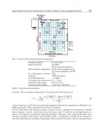
Consider the general system of Figure 19.16.1. Suppose we have a desired movement
of the end effector E. For simplicity (and without loss of generality), let us consider E to
−+
()
−+
()
−−++=
=… +
()
=−
()
mv vq vq I q q
Ie qqmgvMF
nk
k k m kpm
p
kpm
p
kmn k m kpn
p
kpn
p
ksn k m
rsm
kqr kpn
qp j j
k
E
ll
l
ll
ll
˙˙ ˙ ˙ ˙˙
˙
˙
˙˙
,,
ωω ω
ωωω
1
3
0
11 1
Aq f F
˙˙
=+
amvv I
p
k k m kpm kmn k m k n
l
lll
=+ωω
fmvvqI qeI qq
k k m kpm
p
kmn k m kpn
p rsm
ksn k m kqr kpn
pql
ll l
=− + +
()
˙˙
˙
˙˙˙
ωω ωωω
FmgvM F
jj
h
E
ll
l
l
=− + +
−
1
3
F
E
l
0593_C19_fm Page 682 Tuesday, May 7, 2002 9:07 AM
Introduction to Robot Dynamics 683
be a single body (that is, suppose E is a gripper firmly holding an object or workpiece).
Let P be a typical point, perhaps at an extremity, of E as in Figure 19.16.2. For a given
desired motion of E, we will know both the angular velocity of E and the velocity of P.
Let us represent the movement of the system by a series of articulation angles γ
i
(i = 1,…, n), as in Section 19.2. For simplicity (and again without loss of generality) let us
assume a fixed base angle α
B
. Then, we can express the angular velocity of E and the
velocity of P in the forms:
(19.16.1)
where, as before, the n
0m
(m = 1, 2, 3) are unit vectors fixed in the inertia frame R, and the
v
p
ᐉ
m
and ω
E
ᐉ
m
are the partial velocity and partial angular velocities, respectively, of P and
E. Then, with the movement and P and E being known, we will know the n
0m
components
of ωω
ωω
E
and V
P
. These components may then be expressed as:
(19.16.2)
where the g
i
(t) (i = 1,…, 6) are known functions of time.
Equation (19.16.2) may be written in the compact form:
(19.16.3)
where γ is a column array of the articulation angles, g is a column array of functions on
the right sides of Eq. (19.16.2), and B is a block array of partial angular velocity and partial
velocity array components of Eq. (19.16.2). If there are n articulation angles γ
i
(i = 1,…, n),
then γ is an (n × 1) array, g is a (6 × 1) array, and B is a (6 × n) array. B is sometimes called
the constraint matrix.
The articulation angles are governed by the dynamics equations (Eqs. (19.15.3)):
(19.16.4)
If there are n articulation angles γ
i
, Eq. (19.16.4) is equivalent to n scalar equations. Then,
Eqs. (19.16.3) and (19.16.4) form a total of (6 + n) equations for the n γ
i
and the n joint
moments M
i
(i = 1,…, n). Thus, we have (n + 6) equations for 2n unknowns and the system
is undetermined. There are (n – 6) fewer equations than needed to uniquely specify the
FIGURE 19.16.1
Generic robot system.
FIGURE 19.16.2
Representation of an end effector.
E
P
ωω
E
Em m
P
pm m
v==ωγ γ
ll ll
˙˙
nVn
00
and
ωγ γ
Em m pm m
gt V g t m
ll ll
˙˙
,,=
()
=
()
=
+
and
3
123
Bg
˙
γ=
AfF
˙˙
γ= +
0593_C19_fm Page 683 Tuesday, May 7, 2002 9:07 AM
684 Dynamics of Mechanical Systems
motion of the system. Expressed another way, the robot has (n – 6) more degrees of freedom
than needed to uniquely determine the movement of the system. These extra degrees of
freedom represent the redundancy in the system, thus we have a redundant robot.
To resolve the redundancy, we need (n – 6) additional equations or constraints on the
system. As noted earlier, these equations may be obtained in a number of ways, by
specifying some of the articulation angles or by specifying some of the joint torques, or a
combination thereof, or by imposing more general requirements such as having minimum
joint torques or minimum kinetic energy for the system. We will further discuss the form
and solutions of the governing equations in the following sections.
19.17 Constraint Equations and Constraint Forces
Before we look for solutions of the governing equation let us attempt to obtain further
insight into the nature of the equations themselves by considering the following problem.
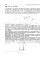
Suppose we have an n-link robot arm with a desired motion of the nth link as in Figure
19.17.1. As before, for simplicity, let us assume that we have a fixed base B. Suppose this
system is initially at rest in an arbitrary configuration. Suppose further that, for this
discussion, the system is in a weightless and force-free environment and that the moments
between adjoining links at the joints are all zero. Imagine further that we are somehow
able to move the nth link through its desired motion. Under these rather specialized
conditions and with the given motion of the nth link, we could ask the question: What
are the resulting motions of the first n – 1 links? That is, in the absence of gravity, with
free movement at the joints, and with a specified movement of the last link, what are the
movements of the first n – 1 links?
To answer this question, consider again the governing dynamical equations (Eqs.
(19.16.4)):
(19.17.1)
where, as before, A is the (n × n) generalized mass array with elements as in Eq. (19.15.4);
γ is the array of articulation angles; f is an array of inertia force terms with elements as in
Eq. (19.15.5); and F is the array of generalized applied forces with elements F
ᐉ
as in
Eq. (19.15.6). In this rather specialized case with no gravity and with zero joint moments,
the F
ᐉ
have the reduced form:
(19.17.2)
FIGURE 19.17.1
An n-link robot with a desired motion
of the last link.
AfF
˙˙
γ= +
FF
ll
=
′
0593_C19_fm Page 684 Tuesday, May 7, 2002 9:07 AM
Introduction to Robot Dynamics 685
where the are generalized forces arising due to the specified motion of the nth link.
That is, the are generalized forces due to the applied forces and movements needed to
drive the nth link through the specified motion. These forces are constraint forces and the
resulting generalized forces of Eqs. (19.17.2) form an array that might be called a
generalized constraint force array.
The specified motion of the nth link also generates a set of constraint equations of the
form of Eq. (19.16.3). That is,
(19.17.3)
Remarkably, the generalized constraint force array F′ is directly related to the constraint
matrix array B by the expression:
(19.17.4)
where λ is an array of constraint force and moment components and B
T
is the transpose
of B. To see this, suppose a point P of the nth link (perhaps a tool point of an end effector)
has a specified motion (see Figure 19.17.2). Suppose further that the angular motion of
the link L
n
is specified. Suppose still further that the specified motions of P and L
n
are
given in the form of velocities or in a form such that the velocity of P and the angular
velocity of L
n
may be determined. Then, the velocity of G
n
, the mass center of L
n
, will be
known or can readily be determined. Let these velocities be expressed in the forms:
(19.17.5)
and
(19.17.6)
where νν
νν
(t) and ΩΩ
ΩΩ
(t) are known (specified) vector functions of time. Referring to the unit
vectors n
0m
of R it is convenient to express V
n
and ωω
ωω
n
in the component forms:
(19.17.7)
FIGURE 19.17.2
Specified motion of link L
n
.
′
F
l
′
F
l
′
F
l
Bg
˙
γ=
′
=FB
T
λ
R
G
n
n
tVV==
()
ν
R
L
n
n
tωωωωΩΩ==
()
Vn n
nm
G
mnm
L
m
V
nn
==
ll ll
˙˙
γωγ
00
and ωω
R
n
n
n
L
V
P
ω
G
P
n
n
n
03
02
01
0593_C19_fm Page 685 Tuesday, May 7, 2002 9:07 AM
686 Dynamics of Mechanical Systems
(Observe that this is different than our usual notation of V
n
ᐉ
m
n
0m
and ω
n
ᐉ
m
n
0m
. The change
is introduced to simplify the matrix analysis of the following paragraphs.) In scalar form,
Eqs. (19.17.5) and (19.17.6) become:
(19.17.8)
where ν
m
(t) and Ω
m
(t), the n
0m
components of νν
νν
and ΩΩ
ΩΩ
, are specified functions of time.
The expressions in Eq. (19.17.8) are constraint equations in the form of Eqs. (19.16.3)
and (19.17.3). Specifically, the constraint matrix B is a (6 × n) array whose elements are
the partial velocity and partial angular velocity components. That is,
(19.17.9)
Then, by comparison of Eqs. (19.17.3), (19.17.8), and (19.17.4), we see that the array g is:
(19.17.10)
Next, let the constraining force system on L
n
be represented by an equivalent force
system consisting of a force passing through G
n
together with a couple with torque
as in Figure 19.17.3. Then, the generalized constraint for force for is (see
Eq. (11.5.7)):
(19.17.11)
FIGURE 19.17.3
Equivalent constraint force system
on link L
n
.
L
G
n
n
M
'
n
F
'
n
Vt tm
m
G
mm
L
m
nn
ll ll
˙˙
,,γν ωγ=
()
=
()
=and Ω 123
B
VVV V
VVV V
VVV V
GGG
n
G
GGG
n
G
GGG
n
G
LLL
n
L
LLL
n
L
LLL
n
L
nnn n
nnn n
nnn n
nnn n
nnn n
nnn n
=
11 12 13 1
21 22 23 2
31 32 33 3
21 12 13 1
21 22 13 2
32 32 33 3
L
L
L
L
L
L
ωωω ω
ωωω ω
ωωω ω
gt
t
t
t
t
t
t
()
=
()
()
()
()
()
()
ν
ν
ν
1
2
3
1
2
3
Ω
Ω
Ω
′
F
n
′
M
n
′
F
l
˙
γ
l
′
=
′
+
′
=…
()
FFV M n
nm m
G
nm m
L
nn
ll l
lω 1, ,
0593_C19_fm Page 686 Tuesday, May 7, 2002 9:07 AM
Introduction to Robot Dynamics 687
where the and are the n
0m
components of and . Let λ be the (6 × 1) column
array of these components. That is,
(19.17.12)
Observe from Eq. (19.17.9) that the transpose of B is:
(19.17.13)
Then, by inspection of Eq. (19.17.11) and by comparison with Eqs. (19.17.12) and (19.17.13),
we see that:
(19.17.14)
thus establishing Eq. (19.17.4).
In view of Eq. (19.17.14) the governing equations, Eqs. (19.17.1) and (19.17.3), may be
written as:
(19.17.15)
and
(19.17.16)
We will consider solutions to these equations in the following section.
19.18 Governing Equation Reduction and Solution: Use of Orthogonal
Complement Arrays
Recall that Eqs. (19.17.15) and (19.17.16) are the governing equations for an n-link robot
whose nth link is driven with a prescribed motion. The joints are moment free, and no
gravitational or externally applied forces are present, other than the constraint forces
′
F
nm
′
M
nm
′
F
n
′
M
n
λ=
′
′
′
′
′
′
F
F
F
M
M
M
n
n
n
n
n
n
1
2
3
1
2
3
B
VVV
VVV
VVV
VVV
T
GGGLLL
GGGLLL
GGGLLL
n
G
n
G
n
G
n
L
n
L
n
L
nnnnnn
nnnnnn
nnnnnn
n n nnnn
=
11 21 31 11 21 31
12 22 32 12 22 32
13 23 33 13 23 33
123123
ωωω
ωωω
ωωω
ωωω
MMMMMM
′
=FB
T
λ
AfB
T
˙˙
γλ=+
Bg
˙
γ=
0593_C19_fm Page 687 Tuesday, May 7, 2002 9:07 AM
688 Dynamics of Mechanical Systems
needed to drive the nth link through its desired motion. Also, the base is fixed. Under
these specialized conditions, Eq. (19.17.15) is equivalent to n scalar equations involving
the n articulation angles γ
i
(i = 1,…, n) and the six constraint (or driving) force and moment
components. Correspondingly, Eq. (19.17.16) is equivalent to six scalar constraint equations
involving the articulation angles. Therefore, taken together, Eqs. (19.17.15) and (19.17.16)
are equivalent to (n + 6) scalar equations for the (n + 6) variables consisting of the n
articulation angles and the six driving force and moment components.
Equations (19.17.15) and (19.17.16) are nonlinear, coupled differential–algebraic equa-
tions. As such, we cannot expect to obtain an analytical solution. Instead, we are left to
seek numerical solutions. Generally, we are more interested in knowing the system motion
than in knowing the constraint force and moment components. Hence, the question arising
is can we reduce and thus simplify the equations by eliminating the λ array? To answer
this question, observe that λ may be eliminated if we could find an (n – 6) × n array (say,
C
T
), with rank (n – 6) such that C
T
B
T
is zero. That is, λ may be eliminated from Eq. (19.17.15)
by premultiplying by C
T
if C
T
B
T
is zero. Equation (19.17.15) then becomes:
(19.18.1)
Equation (19.17.16) may then be differentiated and cast into the same format as:
(19.18.2)
Equations (19.18.1) and (19.18.2) may be combined into a single matrix equation of the
form:
(19.18.3)
where Q is an (n × n) array which has the partitioned form:
(19.18.4)
and h is an (n × 1) column array with the partitioned form:
(19.18.5)
Then, with Q being nonsingular, Eq. (19.18.3) may be solved for the as:
(19.18.6)
Equation (19.18.6) is equivalent to n scalar differential equations for the n articulation
angles. They are in a format that is ideally suited for numerical integration using any of
a number of numerical integration algorithms (solvers).*
* A discussion of such software is beyond our scope here, but interested readers may want to consider numerical
analysis writings, such as References 19.2 to 19.5, for information about such software.
CA Cf
TT
˙˙
γ=
BgB
˙˙
˙
˙
˙
γγ=−
Qh
˙˙
γ=
Q
CA
B
T
=
h
Cf
gB
T
=
−
˙
˙
˙
γ
˙˙
γ
˙˙
γ=
−
Qh
1
0593_C19_fm Page 688 Tuesday, May 7, 2002 9:07 AM
Introduction to Robot Dynamics 689
The key to developing Eq. (19.18.6) is in obtaining the (n – 6) × n array C
T
with rank (n
– 6) such that:
(19.18.7)
Taking the transpose of Eq. (19.18.7), we have:
(19.18.8)
In this context, C is often called an orthogonal complement of B.
One way of obtaining an orthogonal complement of B is to use a rather ingenious zero-
eigenvalues theorem as developed by Walton and Steeves [19.6]. In this procedure, the
(6 × n) array B is premultiplied by its transpose B
T
, forming an (n × n) symmetric array
B
T
B of rank 6. Then, in the eigenvalue problem:
(19.18.9)
there are (n – 6) zero eigenvalues µ. Let x
i
(i = 1,…, n – 6) be the eigenvectors x associated
with the zero eigenvalues. Next, let C be an n × (n – 6) array whose columns are the (n – 6)
eigenvectors x
i
, associated with the zero eigenvalues. Then, with the eigenvalues µ being
zero, we have:
(19.18.10)
Finally, by premultiplying by C
T
we have:
(19.18.11)
Thus, C is the desired orthogonal complement array. Once C is known, the arrays Q
and h may be immediately calculated from Eqs. (19.18.4) and (19.18.5), and the articulation
angles γ
i
may then be obtained by integrating Eq. (19.18.6).
Observe that Eq. (19.18.3) represents a reduced form of the governing equations obtained
by eliminating the constraint force and moment component array λ from Eq. (19.17.15).
If one is interested in knowing these constraint force and moment components, they may
be obtained by back substitution into Eq. (19.17.15). Specifically, Eq. (19.17.15) may be
solved for λ as:
(19.18.12)
19.19 Discussion, Concluding Remarks, and Closure
The foregoing analysis, although somewhat specialized by our simplifying assumptions,
is nevertheless typical of the kinds of analyses used when studying the dynamics of large
CB
TT
= 0
BC = 0
BBx x
T
=µ
BBC
T
= 0
C B BC BC BC BC
BC C B
TT
T
TT
=
()
=
()
=
==
000
00
2
or or
or and
λγ=
()
−
()
−
BB A f
T
1
˙˙
0593_C19_fm Page 689 Tuesday, May 7, 2002 9:07 AM
690 Dynamics of Mechanical Systems
systems. For an actual robot, the analysis would of course be more detailed, but the basic
principles would be the same. In robot hardware design, analysts are concerned with end
effector mechanisms, increased mobility, inverse kinematic problems (determining the
articulation angles to obtain a desired end effector movement), multiple arm systems,
control problems, location sensing, and effects of flexibility and compliance.
The immediate foregoing analysis illustrates a procedure for working with constraint
equations. To discuss this further, consider a matrix form of Kane’s equations for a spec-
ified-motion constrained system (a so-called acatastatic system [19.7]):
(19.19.1)
where F is a column array of generalized applied forces, F* is the corresponding array of
generalized inertia forces, and F′ is an array of constraint forces. The constraint force array
arises as a result of the specified motion of the end effector. The constraint force array is
actually a specialized applied force array due to the forces needed to obtain the specified
end effector motion. In terms of these force components we have seen that F′ has the form:
(19.19.2)
where B is the array of constraint equation coefficients and λ is the array of constraint
force and moment components.
In many cases, the values of the constraint force and moment components are not of
interest. In those cases, their array λ may be eliminated from the analysis by premultiplying
by the transpose of an orthogonal complement C of B. That is, because BC and C
T
B
T
are
zero, Eq. (19.19.1) may be reduced to the form:
(19.19.3)
Equations (19.19.1) and (19.19.3) may be depicted graphically as in Figure 19.19.1, where
F, F*, and F′ form a generalized force triangle representing Eq. (19.19.1). The projection of
F and F* perpendicular to F′, in the form of C
T
F and C
T
F* as shown, represents Eq. (19.19.3).
In this sense, the system may be viewed as being able to move in directions orthogonal
to the constraints.
As we saw in the foregoing analysis, once Eq. (19.19.3) is solved we can use the solution
with back substitution into Eq. (19.19.1) to obtain the force and moment components of
λ, if they are desired.
The references provide a source for more specific information and analysis of robot
systems. As with many other current technologies, robotics is rapidly developing. It is
beyond our scope, however, to attempt to be more detailed about specific systems than
we have been. Our objective has been simply to present an application of our dynamical
procedures. Biomechanics represents another and somewhat related application area that
we will discuss in the following chapter.
FIGURE 19.19.1
Generalized force triangle.
F
F
'
F
C F
*
C F
*
T
T
FF F++
′
=
*
0
′
=FB
T
λ
CF CF
TT
+=
*
0
0593_C19_fm Page 690 Tuesday, May 7, 2002 9:07 AM
Introduction to Robot Dynamics 691
References
19.1. Kane, T. R., Analytical Elements of Mechanics, Vol. 1, Academic Press, New York, 1959, p. 128.
19.2. Champion, E. R., Jr., Numerical Methods for Engineering Applications, Marcel Dekker, New York,
1993.
19.3. Hornbeck, R. W., Numerical Methods, Quantum Publishers, New York, 1975.
19.4. Griffiths, D. V., and Smith, I. M., Numerical Methods for Engineers, CRC Press, Boca Raton, FL,
1991.
19.5. Rice, J. R., Numerical Methods, Software, and Analysis, McGraw-Hill, New York, 1993.
19.6. Walton, W. C., Jr., and Steeves, E. C., A New Matrix Theorem and Its Application for Estab-
lishing Independent Coordinates for Complex Dynamical Systems with Constraints, NASA
Technical Report TR-326, 1986.
19.7. Pars, L. A., A Treatise on Analytical Dynamics, Ox Box Press, Woodbridge, CT, 1979, p. 24.
19.8. Angeles, J., Fundamentals of Robotic Mechanical Systems: Theory, Methods, and Algorithms, Spring-
er-Verlag, New York, 1997.
19.9. Craig, J. J., Introduction to Robotics: Mechanics and Control, Addison-Wesley, Reading, MA, 1989.
19.10. Duffy, J., Analysis of Mechanisms and Robot Manipulators, Edward Arnold, London, 1980.
19.11. Engelberger, J. F., Management and Application of Industrial Robots, American Management
Association, New York, 1980.
19.12. Featherstone, R., Robot Dynamics Algorithms, Kluwer Academic, Dordrecht, 1987.
19.13. Koivo, A. J., Fundamentals for Control of Robotic Manipulators, Wiley, New York, 1989.
19.14. Mason, M. T., and Salisbury, J. K., Robot Hands and the Mechanics of Manipulation, MIT Press,
Cambridge, MA, 1985.
19.15. Murray, R. M., Li, Z., and Sastry, S. S., A Mathematical Introduction to Robotic Manipulation, CRC
Press, Boca Raton, FL, 1993.
19.16. Nakamura, Y., Advanced Robotics: Redundancy and Optimization, Addison-Wesley, Reading, MA,
1991.
19.17. Paul, R. P., Robot Manipulators, Mathematics, Programming, and Control, MIT Press, Cambridge,
MA, 1981.
19.18. Spong, M. W., and Vidyasagar, M. M., Dynamics and Control of Robot Manipulators, Wiley, New
York, 1989.
Problems
Section 19.2 Geometry, Configuration, and Degrees of Freedom
P19.2.1: Refer to the simple planar robots shown in Figures P19.2.1a and b consisting of
two- and three-link arms, respectively, and consider the following questions:
1. How many degrees of freedom does each system have?
2. What are the hinge inclination angles for these systems?
3. From an analysis perspective, what are the relative advantages and disadvan-
tages of these systems?
4. From an applications perspective, what are the relative advantages and disad-
vantages of these systems?
P19.2.2: Consider the simple end effector, or gripper, shown in Figure P19.2.2. If this end
effector were attached to the extremities of the systems of Problem P19.2.1, what would
0593_C19_fm Page 691 Tuesday, May 7, 2002 9:07 AM
692 Dynamics of Mechanical Systems
be the resulting degrees of freedom of each system? Would the presence of the end effector
affect the relative advantages and disadvantages of each system?
P19.2.3: Consider a robot arm consisting of four identical links each having length 0.5 m
(Figure P19.2.3). Let the links be pin-connected to each other with articulation angles γ
i
(i = 1,…, 4) as defined in Section 19.2. Also, let the pin axes be oriented relative to each
other with inclination angles α
i
(i = 1,…, 4), as defined in Section 19.2. Let the α
i
and γ
i
have the values:
Determine the coordinates of the extremity E of the fourth link relative to an axis system
fixed in the base B with origin O
1
.
P19.2.4: Repeat Problem P19.2.3 if the link lengths are 12 inches long and the inclination
and articulation angles are:
Section 19.3 Transformation Matrices and Configuration Graphs
P19.3.1: See Problem P19.2.3. Let the robot arm links be numbered outward from the base
B. Using the angles listed in the problem statement, determine the transformation matrices,
S01, S02, S03, and S04. Assume that the base B is fixed in the inertial reference frame R
(that is, S0B = I).
P19.3.2: Repeat Problem P19.3.1 for the orientation angles listed in Problem P19.2.4.
FIGURE P19.2.1
Two- and three-link planar robots.
FIGURE P19.2.2
An end effector.
FIGURE P19.2.3
A robot arm consisting of four identical
pin-connected links.
a. Two-Link System b. Three-Link System
αααα
γγγγ
1234
12 3 4
45
15 30 45 60
====°
=° =° =° =°,,,
B
E
O
1
αααα
γγγγ
1234
1234
30
60 45 30 15
====°
=° =° =° =°,,,
0593_C19_fm Page 692 Tuesday, May 7, 2002 9:07 AM
Introduction to Robot Dynamics 693
Section 19.4 Angular Velocity of Robot Links
P19.4.1: Consider a robot arm with six links L
k
(k = 1,…, 6) connected to each other by
hinge joints as in Figure 19.4.4 and with a rotating base B as in Figure 19.4.2, as represented
in Figure P19.4.1. Let the orientation of the links be defined by the angles α
k
(k = 1,…, 6)
as in Section 19.4. How many degrees of freedom does this system have? Using the notation
and unit vector directions of Section 9.4, develop expressions for the transformation
matrices S0K (K = 1,…, 6).
P19.4.2: See Problem P19.4.1. Let the orientation angles α
k
(k = 1,…, 6) of the link axes and
the articulation angles α
B
and γ
k
(k = 1,…, 6) and be:
Determine the numerical values of the elements of the transformation matrices S0K
(K = 1,…, 6).
P19.4.3: See Problems P19.4.1 and P19.4.2. Develop equations analogous to Eq. (19.4.9) for
the robot links of the system of Figure P19.4.1 with the angles α
k
(k = 1,…, 6) of Problem
P19.4.2.
P19.4.4: See Problem P19.4.3. Develop more explicit expressions for the link angular
velocities if at an instant of interest the articulation angles α
B
and γ
k
(k = 1,…, 6) are:
P19.4.5: See Problem P19.4.4. Let the articulation angle rates all be equal to 30 rpm.
Determine the link angular velocities in terms of unit vectors n
0i
fixed in the inertia frame
R. Assume the orientation angles α
k
(k = 1,…, 6) and the articulation angles α
B
and γ
k
(k = 1,…, 6) are the same as those of Problems P19.14.2 and P19.14.4.
P19.4.6: See Problems P19.4.1 and P19.4.5. Suppose all the orientation angles α
k
(k = 1,…, 6)
as well as α
B
are zero. We then have a planar robot. Repeat Problems P19.4.1 to P19.4.5
for this planar system.
FIGURE P19.4.1
A robot with six links and a rotating base.
R
B
L
L
L
L
L
L
1
2
3
4
5
6
αα αα αα
γγγγγγ
α
12 34 56
123456
0 90 0 90 0 90
30 45 60 45 30 45
30
==°==−°==°
=° =° =° =° =° =°
=°
,,, ,,
,,,,,
B
αγγγ
γγγ
B
=° =° =° =°
=° =° =°
30 30 45 60
45 30 45
123
456
,,,
,,
0593_C19_fm Page 693 Tuesday, May 7, 2002 9:07 AM
694 Dynamics of Mechanical Systems
Section 19.5 Partial Angular Velocities
P19.5.1: See Problems P19.4.1 to P19.4.6. Develop expressions for the partial angular
velocity components as in Eq. (19.5.4) for the system of Figure P19.4.1 as described in
Problems P19.4.1 to P19.4.6.
Section 19.6 Transformation Matrix Derivative
P19.6.1: See Problems P19.3.1 and P19.3.2. Determine, by direct differentiation, the deriv-
ative of the transformation matrices.
P19.6.2: See Problems P19.2.3 and P19.2.4. Determine expressions for the link angular
velocities.
P19.6.3: See Problem P19.6.2. Use the results of Problem P19.6.2 to determine the WK
(K = 1,…, 4) as defined by Eq. (19.6.3) for the robot links. Then, use Eq. (19.6.4) to determine
the transformation matrix derivatives. Compare the results with those of Problem P19.6.1.
P19.6.4: Repeat the procedure of Problems P19.6.1, P19.6.2, and P19.6.3 for the robot system
of Problem P19.4.1.
Section 19.7 Angular Acceleration of Robot Links
P19.7.1: Consider again the robot system of Problem P19.2.3 consisting of four identical
pin-connected links and as shown again in Figure P19.7.1. Recall that the hinge inclination
angles α
k
(k = 1,…, 4) are all 45°. At an instant of interest, let the articulation angles γ
k
(k = 1,…, 4) and their derivatives be:
Let the base B be, and remain, at rest in an inertial frame R. Using the results of Problems
P19.3.1, P19.6.1, and P19.6.3, determine the angular acceleration of the robot links. Express
the results in terms of unit vectors fixed in R.
P19.7.2: Repeat Problem P19.7.1 for the following data:
FIGURE P19.7.1
The robot arm of Problem P19.2.3 with
four identical pin-connected links.
γγγγ
γ
π
γπ γ
π
γπ
γγγγ
1234
1234
1234
15 30 45 60
2
3
2
2
10 0
=° =° =° =°
====
=− = = =
,,,
˙
sec,
˙
sec,
˙
sec,
˙
sec
˙˙
,
˙˙
,
˙˙
,
˙˙
rad rad rad rad
rad sec 1 rad sec
22
γγ γγ
γπ γ
π
γπ γ
π
γγ γγ
12 34
12 34
12 34
60 45 30 15
2
3
22
01 01
=° =° =° =°
== ==
== ==−
,, ,
˙
,
˙
,
˙
,
˙
˙˙
,
˙˙
,
˙˙
,
˙˙
rad sec rad sec rad sec rad sec
rad sec rad sec
22
0593_C19_fm Page 694 Tuesday, May 7, 2002 9:07 AM
Introduction to Robot Dynamics 695
P19.7.3: Consider again the robot system of Problem P19.4.1 consisting of six pin-connected
links and a rotating base as shown again in Figure P19.7.3. As in Problems P19.4.2 and
P19.4.5, let the orientation and articulation angles and their derivatives have the values:
Let the second derivatives of the articulation angles have the values:
Let the second derivatives of the articulation angles have the values:
Using the results of Problems P19.4.2, P19.4.3, P19.4.5, and P19.6.4, determine the angular
accelerations of the links and the base. Express the results in terms of unit vectors fixed
in the inertial frame R.
P19.7.4: See Problem P19.4.6. Suppose that all the orientation angles of the robot arms of
Problems P19.7.1 and P19.7.3 are zero so that they are planar robots. Using the data of Problems
P19.7.1 and P19.7.3, determine the angular accelerations of the links for each system.
Section 19.8 Joint and Mass Center Position
P19.8.1: See Problems P19.2.3 and P19.3.1. Consider again the robot arm of Problem P19.2.3
as shown in Figure P19.2.3 and as shown again in Figure P19.18.1. Let the length of each
link be 12 in., let the origin O
1
of the first link be at the top of a fixed base B as shown,
and let O
1
be 6 in. above a fixed point O in an inertial frame R. Let the orientation and
articulation angles be as listed in Problem P19.2.3. That is,
FIGURE P19.7.3
The robot of Problem P19.4.1 with six
links and a rotating base.
αα αα αα
γγγγγγ
α
γγγγγγαπ
12 34 56
123456
123456
0 90 0 90 0 90
30 45 60 45 30 45
30
==°==−°==°
=° =° =° =° =° =°
=°
=======
,,, ,,
,,,,,
˙˙˙˙˙˙
˙
B
B
rad sec
2
˙˙
,
˙˙
,
˙˙
,
˙˙
˙˙
,
˙˙
,
˙˙
γγγ γ
γγα
123 4
56
1010
100
===−=
===
rad sec rad sec
rad sec
22
2
B
˙˙
,
˙˙
,
˙˙
,
˙˙
˙˙
,
˙˙
,
˙˙
γγγ γ
γγα
123 4
56
1010
100
===−=
===
rad sec rad sec
rad sec
22
2
B
0593_C19_fm Page 695 Tuesday, May 7, 2002 9:07 AM
696 Dynamics of Mechanical Systems
Determine an expression for the position vector P
E
locating the end effector origin E
relative to O.
P19.8.2: See Problems P19.8.1, P19.2.4, and P19.5.2. Repeat Problem P19.8.1 if the robot
link lengths are 0.25 m and if O
1
is 0.125 m above O. Let the orientation and articulation
angles be those of Problem P19.2.4. That is,
P19.8.3: See Problems P19.4.1, P19.4.2, and 19.4.3. Consider again the robot arms of Problem
P19.4.1 as shown in Figure P19.4.1 and as shown again in Figure P19.8.3. Use the following
lengths of the robot links L
k
: L
1
and L
2
, 6 in.; L
3
and L
4
, 8 in.; L
5
and L
6
, 12 in. Let the origin
O
1
of link L
1
be 6 in. above a fixed point O of the inertial frame R. Finally, let the orientation
and articulation angles be those listed in Problem P19.4.2. That is,
Determine an expression for the position vector P
E
locating the origin of an end effector
at the extremity of link L
6
relative to O.
FIGURE P19.8.1
A robot arm with four identical
pin-connected links.
FIGURE P19.8.3
A robot with six pin-connected links
and a rotating base B.
αααα
γγγγ
1234
12 3 4
45
15 30 45 60
====°
=° =° =° =°,,,
αααα
γγγγ
1234
1234
30
60 45 30 15
====°
=° =° =° =°,,,
αα αα αα
γγγγγγα
12 34 56
123456
0 90 0 90 0 90
30 45 60 45 30 45 30
==°==−°==°
=° =° =° =° =° =° =°
,,, ,,
,,,,,,
B
0593_C19_fm Page 696 Tuesday, May 7, 2002 9:07 AM
Introduction to Robot Dynamics 697
P19.8.4: Repeat Problem P19.8.3 if the link lengths are L
1
and L
2
, 12 in.; L
3
and L
4
, 8 in.;
L
5
and L
6
, 6 in.
P19.8.5: Repeat Problems P19.8.1 to P19.8.4 if all the articulation angles α
k
including α
B
are zero. That is, repeat the problems for planar robots.
P19.8.6: See Problems 19.8.1 and 19.8.2. Let the robot links be uniform in cross section so
that the mass center is at mid-link. Determine expressions for the mass center position
vectors using the data of Problems P19.8.1 and P19.8.2.
P19.8.7: See Problems P19.8.3 and P19.8.4. Let the robot links be uniform so that the mass
center is at mid-link. Determine expressions for the mass center position vectors using the
data of Problems P19.8.3 and P19.8.4.
P19.8.8: See Problem P19.8.5. Repeat Problems P19.8.6 and P19.8.7 for the robots with a
planar configuration.
Section 19.9 Mass Center Velocities
P19.9.1: See Problem P19.8.6. Determine expressions analogous to Eq. (19.9.3) for the robot
link mass center velocities for the robot arm of Figure P19.8.1. Let the articulation angle
derivatives (k = 1,…, 4) be arbitrary.
P19.9.2: See Problem P19.8.7. Determine expressions analogous to Eq. (19.9.3) for the robot
link mass center velocities for the robot arm of Figure P19.8.3. Let the articulation angle
derivatives and (k = 1,…, 4) be arbitrary.
P19.9.3: See Problem P19.8.8. Determine expressions analogous to Eqs. (19.9.3) for the
robot link mass center velocities for the robot with planar arm configurations. Let the
articulation angle derivatives be arbitrary.
P19.9.4: Repeat Problems P19.9.1, P19.9.2, and P19.9.3 if the articulation angle rates are
all 30 rpm.
Section 19.10 Mass Center Partial Velocities
P19.10.1: Use the results of Problems P19.9.1, P19.9.2, and P19.9.3 to identify the partial
velocity vectors for the systems studied.
Section 19.11 Mass Center Accelerations
P19.11.1: Using the data and results of Problems P19.9.1, P19.9.2, and P19.9.3, determine
expressions for the link mass center acceleration in the inertial frame R for the systems
studied. Let the articulation angle derivatives and second derivatives be arbitrary.
P19.11.2: Consider again the robot system of Figure P19.11.2 and as studied in Problems
P19.2.3, P19.2.4, P19.3.1, P19.3.2, P19.9.1, P19.9.3, and P19.10.1. For the data given in these
problems, determine the accelerations of the link mass centers in the inertial frame R.
P19.11.3: Consider again the robot system of Figure P19.11.3 and as studied in Problems
P19.4.1 to P19.4.6, P19.5.1, P19.6.4, P19.7.3, P19.7.4, P19.8.3, P19.8.4, P19.8.5, P19.8.7, P19.8.8,
P19.9.2, P19.9.3, and P19.10.1. For the data given in these problems, determine the accel-
eration of the link mass centers in the inertial frame R.
˙
γ
k
˙
α
B
˙
γ
k
0593_C19_fm Page 697 Tuesday, May 7, 2002 9:07 AM
698 Dynamics of Mechanical Systems
Section 19.12 End Effector Kinematics
P19.12.1: Design an end effector able to firmly grasp a sphere.
P19.12.2: Let an end effector consist of three two-link fingers spaced 120° from one another
as shown in Figure P19.12.2. Let the finger links have equal lengths, and let the connecting
and supporting joints be revolute, or hinge, joints with axes oriented at 120° relative to
one another from finger to finger. Develop the kinematics of this system.
Section 19.13 Kinetics: Applied (Active) Forces
P19.13.1: Illustrate the use of Eqs. (19.13.4), (19.13.10), and (19.13.11) with the relatively
simple three-link planar robot arm shown in Figure P19.13.1. Specifically, let the arm
consist of three pin-connected links L
1
, L
2
, and L
3
which are rotated relative to their adjacent
lower numbered links by joint located actuators exerting torques T
1
, T
2
, and T
3
, as shown.
Let the links have masses m
1
, m
2
, and m
3
and lengths ᐉ
1
, ᐉ
2
, and ᐉ
3
. Let there be an end
effector E with mass M at the extremity of L
3
. Let F be an externally applied force on E
with horizontal and vertical components F
x
and F
g
. Finally, let β
1
, β
2
, and β
3
be orientation
angles measured between the links as shown. Determine the generalized applied forces
on the system using β
1
, β
2
, and β
3
as generalized coordinates.
Section 19.14 Kinetics: Passive (Inertia) Forces
P19.14.1: Using Eqs. (19.4.1) to (19.4.5), verify Eqs. (19.14.6) to (19.14.9).
P19.14.2: Consider again the simple three-link robot arm of Problem P19.13.1. Using the
same data as in Problem P19.13.1 and using β
1
, β
2
, and β
3
as generalized coordinates,
determine the generalized inertia forces on the system.
FIGURE P19.11.2
A robot arm with four identical, uniform,
pin-connected links.
FIGURE P19.11.3
A robot with six uniform pin-connected links and a
rotating base.
FIGURE P19.12.2
A three-fingered end effector.
120°
120°
120°
0593_C19_fm Page 698 Tuesday, May 7, 2002 9:07 AM
Introduction to Robot Dynamics 699
Section 19.15 Dynamics: Equations of Motion
P19.15.1: Using Eqs. (19.13.11), (19.14.8), and (19.15.1), verify Eqs. (19.15.2) through
(19.15.6).
P19.5.2: See Problems P19.13.1 and P19.14.2. Determine the equations of motion of the
simple three-link robot shown in Figure P19.13.1. (Use the same data and parameters as
in Problems P19.13.1 and P19.14.2.)
Sections 19.16 Redundant Robots
P19.16.1: Consider the system of three identical pin-connected rods moving in a horizontal
plane as represented in Figure P19.16.1. Let the rods each have length
ᐉ and mass m, and
let the connecting pins be frictionless. Let the orientation of the rods in the plane be defined
by the relative angles γ
1
, γ
2
, and γ
3
as shown. Finally, let the movement of the extremity E
be specified. Specifically, let the plane of movement of the system be the X–Y plane as
shown and let the coordinates (x, y) of E be specified functions of time as:
Develop the governing equations for this system. That is, determine the constraint equa-
tions as in Eq. (19.16.3) and the dynamic equations as in Eq. (19.16.4).
P19.16.2: See Problem 19.16.1. Repeat Problem P19.16.1 if E is required to move on a circle
of radius r with center C (x
O
, y
O
) where r, x
O
, and y
O
are compatible with the geometry of
the system.
FIGURE P19.13.1
A three-link planar joint actuated
robot arm.
FIGURE P19.16.1
A three-link system with prescribed
motion of the extremity.
Y
E
T
L
F
X
T
T
L
L
1
2
3
1
2
3
β
β
β
2
3
1
xt y t=
()
=
()
φψand
Y
X
O
γ
γ
γ
1
2
3
E (x,y)
0593_C19_fm Page 699 Tuesday, May 7, 2002 9:07 AM
700 Dynamics of Mechanical Systems
P19.16.3: See Problems P19.16.1 and P19.16.2. Repeat Problems P19.16.1 and P19.16.2 if
the orientation of the rods is defined by the absolute angles θ
1
, θ
2
, and θ
3
as in Figure
P19.16.3.
Section 19.17 Constraint Equations and Constraint Forces
P19.17.1 See Problems P19.16.1, P19.16.2, and P19.16.3. Use Eq. (19.17.4) to determine the
generalized constraint array Identify the components of the λ array.
Section 19.18 Governing Equation Reduction and Solution: Use of Orthogonal
Complement Arrays
P19.18.1: See Problems P19.16.1, P19.16.2, P19.16.3, and P19.17.1. Determine an orthogonal
complement array C of B.
P19.18.2: See Problem P19.18.1. Use Eq. (19.18.12) to determine an expression for the
components of the constraint force array λ.
FIGURE P19.16.3
A three-link system with prescribed
extremity motion described by absolute
orientation angles.
Y
X
O
1
2
3
E (x,y)
θ
θ
θ
′
F
l
.
0593_C19_fm Page 700 Tuesday, May 7, 2002 9:07 AM
701
20
Application with Biosystems, Human Body Dynamics
20.1 Introduction
In this final chapter, we apply the foregoing procedures with biosystems, principally the
human body. Interest in this application is growing faster than for any other area of
dynamics analysis. This interest is stimulated by unanswered questions about human
body dynamics arising in regard to the workplace, accidents, sport activities, space explo-
ration, and routine daily activities. The principal areas of interest are performance enhance-
ment, understanding causes of injury, and rehabilitation from injury and illness.
As with robotics, the application of dynamics procedures with biosystems is more
extensive than can be covered, or even summarized, in a single chapter. Hence, our
purpose is to simply introduce the application, to discuss specific problems, and to propose
methods of analysis. Readers interested in more in-depth analyses may want to consult
the references at the end of the chapter.
Unlike a robot, a biosystem — specifically, the human body — is more complex and
less well defined. The human form is not composed of simple geometrical shapes, and,
even if the body is studied in small parts such as with arms, hands, or fingers, the analysis
is not simple. Indeed, even the location of the mass center of elemental parts is imprecise,
and comprehensive analyses of joint kinematics are extremely difficult.
These difficulties, while apparently formidable, are nevertheless intriguing and chal-
lenging to dynamics analysts. As such they provide motivation for the development of
modeling and analysis procedures. As with other mechanical systems, the objective is to
find simple models that are sufficiently representative of the physical system to provide
useful information.
To this end, Figure 20.1.1 shows a typical whole-body or gross-motion model of the
human body. It consists of a series of bodies representing the main parts of a human frame.
These bodies have relatively simple geometric shapes: ellipsoids, elliptical cylinders, and
frustums of elliptical cones. They are assembled in the form of the human frame and are
connected by pin and spherical joints simulating the human joints. Springs and dampers
are used to represent the restraining and articulation effects of the ligaments, muscles,
and other connective tissues.
This model is well suited for studying overall gross motion of the human body as might
occur in the workplace, in sport activities, and due to accidents or injuries. The model is
also suitable for health and fitness studies as in analyses of exercise maneuvers and in the
design of rehabilitative devices such as wheelchairs, crutches, and braces. We will discuss
some of these applications in the sequel, but, as before, our focus will be upon dynamic
analysis and, specifically, the methods for obtaining the governing dynamical equations.
0593_C20_fm Page 701 Tuesday, May 7, 2002 9:14 AM
702
Dynamics of Mechanical Systems
20.2 Human Body Modeling
The model of Figure 20.1.1 and shown again in Figure 20.2.1 is a
global
or gross representation
of the human frame. The segments represent the major human links. They are connected
with pin and spherical joints. The actuating muscles and ligaments are represented by
springs and dampers. The segments themselves are in the form of elementary geometrical
shapes such as ellipsoids, elliptical cylinders, cones, and frustums of elliptical cones. As
such, the modeling system is a rather simplified and idealized representation of the human
body. It is best used for gross-motion simulation. It is not particularly useful for studying
the movement of individual body parts such as the hands, the feet, or even the head/neck
system. Also, a close examination of the human joints shows that they are not pins or
spherical joints. Instead they are somewhat more complex, having both translation and
rotation between adjoining bodies. Therefore, if we are interested in a more detailed repre-
sentation of the human than that of Figure 20.2.2, we will need more detailed models.
Figure 20.2.2 shows a more detailed model of the head and neck system. Here, the
individual bodies represent the vertebrae, the upper torso, and the head. In head and neck
studies, the effects of the discs, muscles, and ligaments connecting and separating the
vertebrae are of particular interest. These may be effectively modeled by nonlinear springs
and dampers. For example, suppose
θ
represents a relative rotation of a pair of adjoining
vertebrae. Then, the moment exerted by the discs, muscles, and ligaments on the vertebrae
may be represented by an equivalent moment
M
of the form [20.10, 20.14, 20.16]:
(20.2.1)
FIGURE 20.1.1
A gross-motion human body model.
FIGURE 20.2.1
A global representation of the human frame.
M
Mkc
Mkc
M
M
=≤≤
=− − −
()
>>
=− − −
()
<<
><
=< >
0
0
0
0
00
11
22
for
for and
for and
= 0 for and
for and
θθθ
θθθθ θθ θ
θθθθ θθ θ
θθ θ
θθ θ
min max
max max
min min
max
min
˙˙
˙˙
˙
˙
0593_C20_fm Page 702 Tuesday, May 7, 2002 9:14 AM
Application with Biosystems, Human Body Dynamics
703
where
θ
min
and
θ
max
are minimum and maximum rotations, respectively, that establish
limits of normal movement before pain is experienced and where
k
1
,
k
2
,
c
1
, and
c
2
are
constants.
Observe in Eq. (20.2.1) that the moment is nonlinearly dependent upon the rate of
movement beyond the limiting values
θ
min
and
θ
max
. Observe further that the “restoring”
aspect of
M
is zero when the vertebrae are returning to their normal movement range.
This nonlinearity is based upon empirical data [20.10, 20.14, 20.16, 20.18, 20.19]. Finally,
if our interest is in hand movement we might use a model as in Figure 20.2.3.
In many cases of interest, the models of Figures 20.2.1, 20.2.2, and 20.2.3 are useful in
providing information about both the movement and forces experienced during various
activities. With smaller bodies such as the fingers and vertebrae, the applied forces, such
as the muscle and ligament forces, greatly exceed the inertia forces. Also, in many instances
such as hand modeling, interest in the movement (that is, the kinematics) is greater than
interest in the forces.
A question arising in the development of these models is what are the values of the
physical and geometrical parameters (that is, the masses, the inertia matrix components,
the sizes, and the movement limits) for the various members of the models? The somewhat
unsatisfying answer is these values depend upon the particular individual and may vary
considerably. Banks of data, however, are available for individuals of varying sizes. Ref-
erences 20.9, 20.20, and 20.21 are good sources for such data.
In the sequel for simplicity, but without loss of generality, we will focus our discussion
upon the whole-body model of Figure 20.2.1. As with robotic systems, we will initially
consider the kinematics, kinetics, and dynamics. We will then briefly discuss applications.
20.3 A Whole-Body Model: Preliminary Considerations
Consider again the model of Figure 20.2.1 and as redrawn here in Figure 20.3.1. Let the
individual bodies of the model be numbered as shown, consistent with the procedures
used with lower body arrays (see Section 18.2). As before, let
R
be an inertial reference
frame in which the system moves. Table 20.3.1 then provides a listing and labeling of the
various links and segments of the model. By inspection of Figure 20.3.1, we then imme-
diately obtain the lower body array
L
(
K
) as follows:
FIGURE 20.2.2
A model of the head/neck system.
FIGURE 20.2.3
A hand model.
K:01234567891011121314151617
L(K):00123453739101121311516
0593_C20_fm Page 703 Tuesday, May 7, 2002 9:14 AM
704
Dynamics of Mechanical Systems
By following the procedures of Section 18.2, we then obtain the higher-order lower body
arrays as listed in Table 20.3.2.
Observe in the lower body array
L
(
K
) that the repeated numbers are 1 and 3, designating
the branching bodies. The missing numbers are 6, 8, 11, 14, and 17, designating extremities.
The numbers appearing only once are 2, 4, 5, 7, 9, 10, 12, 13, 15, and 16, designating
intermediate bodies. Table 20.3.3 provides a summary listing of these.
Consider two typical adjoining bodies of the system such as
B
j
and
B
k
as in Figure 20.3.2.
Let
B
j
be the lower numbered body. As in our previous analyses, let the bodies be
connected by a spherical joint. Let
n
ji
and
n
ki
(
i
= 1, 2, 3) be mutually perpendicular unit
vectors fixed in
B
j
and
B
k
as shown. Then, as before, the orientation of
B
k
relative to
B
j
may be defined in terms of a transformation matrix (or direction cosine matrix) SJK whose
elements
SJK
min
are:
(20.3.1)
FIGURE 20.3.1
A numbered whole-body model.
TABLE 20.3.1
A Listing and Labeling of the Segments of Figure 20.3.1
Body Number Label Name
0
R
Inertial reference frame
1
B
1
Lower torso/pelvis
2
B
2
Mid-torso/abdomen
3
B
3
Upper torso/chest
4
B
4
Upper left arm
5
B
5
Lower left arm
6
B
6
Left hand
7
B
7
Neck
8
B
8
Head
9
B
9
Upper right arm
10
B
10
Lower right arm
11
B
11
Right hand
12
B
12
Upper right leg/right thigh
13
B
13
Lower right leg
14
B
14
Right foot
15
B
15
Upper left leg/left thigh
16
B
16
Lower left leg
17
B
17
Left foot
8
4
5
6
3
2
1
9
10
11
7
12
15
13
16
14
17
SJK
mn jm
kn
=⋅nn
0593_C20_fm Page 704 Tuesday, May 7, 2002 9:14 AM
Application with Biosystems, Human Body Dynamics
705
Recall also from our previous analyses that we can describe the orientation of
B
k
relative
to
B
j
in terms of orientation angles such as dextral orientation angles (or Bryan angles) as
follows: let the unit vectors
n
ji
and
n
ki
be mutually aligned — that is, with the
n
ki
parallel
to the
n
ji
(
i
= 1, 2, 3), respectively. Then,
B
k
may be brought into a general orientation
relative to
B
j
by three successive rotations of
B
k
about axes parallel to
n
k
1
,
n
k
2
, and
n
k
3
through angles
α
k
,
β
k
, and
γ
k
, which are positive when the rotation is dextral (or right-
handed). When this is done, the transformation matrix SJK has the form (see Eq. (18.3.4)):
(20.3.2)
where as before
s
and
c
are abbreviations for sine and cosine.
Recall from Section 18.5 that the use of orientation angles, although conceptually simple,
allows singularities to occur under certain orientations of the bodies. Specifically, for the
TABLE 20.3.2
Higher-Order Lower Body Arrays for the Model of Figure 20.3.1
L
0
(
K
) 01234567891011121314151617
L
1
(
K
) 00123453739101121311516
L
2
(
K
) 00012342323901120115
L
3
(
K
) 000012312123001001
L
4
(
K
) 000001201012000000
L
5
(
K
) 000000100001000000
L
6
(
K
) 000000000000000000
TABLE 20.3.3
Branching Bodies, Intermediate Bodies and Extremities for the
Model of Figure 20.3.1
Branching Bodies Intermediate Bodies Extremities
Lower torso (
B
1
) Mid-torso (
B
2
) Left hand (
B
6
)
Upper torso (
B
3
) Upper left arm (
B
4
) Head (
B
8
)
Lower left arm (
B
5
) Right hand (
B
11
)
Neck (
B
2
) Right foot (B
14
)
Upper right arm (B
9
) Left foot (B
17
)
Lower right arm (B
10
)
Upper right leg (B
12
)
Lower right leg (B
13
)
Upper left leg (B
15
)
Lower left leg (B
16
)
FIGURE 20.3.2
Two typical adjoining bodies.
SJK
cc cs s
cs ssc cc sss sc
ss csc sc css cc
kk kk k
kk kkk kk kkk kk
kk kkk kk kkk kk
=
−
+
()
−
()
−
−
()
+
()
βγ βγ β
αγ αβγ αγ αβγ αβ
αγ αβγ αγ αβγ αβ
n
B
B
n
n
n
n
n
j
k
j3
j2
j1
k3
k2
k1
0593_C20_fm Page 705 Tuesday, May 7, 2002 9:14 AM
706 Dynamics of Mechanical Systems
Bryan angles, there is a singularity where β
k
is either 90° or 270°. From a computational
(or numerical analysis) viewpoint, it is necessary to avoid these singularities if the range
of motion of the bodies allows them to occur. As we saw in Section 18.5, the singularities
may be avoided through use of Euler parameters, where B
k
is envisioned to be brought
into a general orientation relative to B
j
by a rotation about an axis fixed in both B
j
and B
k
.
Then, if λλ
λλ
k
is a unit vector parallel to this axis and if θ
k
is the rotation angle, the Euler
parameters may be defined as:
(20.3.3)
where the λ
ki
(i = 1, 2, 3) are the n
ji
components of λλ
λλ
k
. The transformation matrix SJK may
then be written as (see Eq. (18.5.14)):
(20.3.4)
Observe in these two methods for describing the relative orientation of adjoining bodies
that the orientation angles are somewhat easier to visualize in terms of actual limb con-
figuration and movement. The Euler parameters, however, have the computation advan-
tage. As we saw in Section 18.9, it is possible in computer analyses to take advantage of
the desirable features of each method by making transformations between the two. Then
computations may be made using Euler parameters while the relative body orientation
and movement are described by the orientation angles.
Observe further that from a strict anatomical perspective it may not be accurate to use
spherical joints to represent the body joints. For example, a spherical joint does not allow
translation to occur between adjoining bodies (such as neck stretching). Also, knees and
elbows might better be modeled as revolute (or hinge) joints, and even shoulders and hips
are not exactly spherical joints. For gross motion simulations, however, these are generally
unimportant concerns in that joint translation between adjoining bodies is relatively small.
Also, revolute or hinge joints may be regarded as a specialization of a spherical joint where
two of the angles are assigned zero values.
Finally, in Figure 20.3.1 we will regard the model to be in its reference configuration,
where it is standing erect with legs together and arms at the sides with palms facing
forward. The axes of each body are then all respectively parallel, with the X-axis being
forward, the Z-axis vertically up, and the Y-axis to the left.
20.4 Kinematics: Coordinates
In the foregoing chapters, we have developed methods for obtaining kinematical expres-
sions for multibody systems. Those same methods are applicable here. Indeed, obtaining
ελ θ
ελ θ
ελ θ
εθ
kk k
kk k
kk k
kk
11
22
33
4
2
2
2
2
=
()
=
()
=
()
=
()
sin
sin
sin
cos
SJK
k k k k kk kk kk kk
kk kk k k k k kk kk
kk
=
−−+
()
−
()
+
()
+
()
−+ − +
()
−
()
−
ε ε ε ε εε εε εε εε
εε εε ε ε ε ε εε εε
εε
1
2
2
2
3
2
4
2
12 34 13 24
12 34 1
2
2
2
3
2
4
2
23 14
13
22
22
2 εεε εε εε ε ε ε ε
kk kk kk k k k k24 23 14 1
2
2
2
3
2
4
2
2
()
+
()
−− + +
()
0593_C20_fm Page 706 Tuesday, May 7, 2002 9:14 AM