Advances in Haptics Part 9 potx
Bạn đang xem bản rút gọn của tài liệu. Xem và tải ngay bản đầy đủ của tài liệu tại đây (2.05 MB, 45 trang )
AdvancesinHaptics352
As shown above, polynomial as well as the RBF interpolation can be explored in the on-line
phase of the scheme to approximate the actual configuration in real-time using the precom-
puted data. In the following section, some details concerning the implementation and evalu-
ation of the algorithms presented before are given.
3.4 Evaluation and Discussion
In our prototype implementation, both the scheduler and pool of the solvers were imple-
mented in C++ programming language. The communication between the remote processes
was provided by Message-Passing Interface (MPICH implementation ver. 1.2.7 communicat-
ing over sockets). The configurations represented by the various deformation of the object
were using using GetFEM, an open-source FEM library. The solution of the linearized system
computed in each iteration of the Newton-Raphson method was performed by MUMPS lin-
ear solver (see P.R.Amestoy et al. (2000)). Further, the force interpolator was implemented
for the interpolation techniques presented in section 3.3. The interpolation of the forces was
stably running at a frequency of 1,000 Hz on a workstation equipped with 2
× Dual Core AMD
Opteron 285 processor. Similarly, precomputed nodal displacements were utilized by shape
interpolator computing the actual deformation of the body for the visualization purposes run-
ning at 25 Hz.
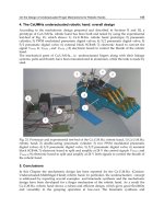
The experiments evaluated in the next part of this section were performed on 3D model
of human liver obtained from the INRIA repositories. The model was meshed by TetGEN
mesh generation tool resulting in two meshes with 1777 elements (501 nodes) and 10280 el-
ements (2011 nodes), respectively. The real length of the model was about 22cm. We use
both Mooney-Rivlin and StVenant-Kirchhoff material laws; in the case of Mooney-Rivlin, the
incompressibility conditions were imposed by mixed formulation.
Extensive testing has been performed to validate the approach based on the precomputation
of the configuration spaces. The evaluation can be divided into two parts as follows. First, the
accuracy of the methods has been studied. For this purpose, a large number of configurations
has been computed and stored for a random values of the positional data. The approximated
counterparts have been generated by the interpolation of the precomputed spaces, the forces
and displacements have been compared and evaluated. The mean and maximum errors have
been calculated using the large set of computed data as shown in Peterlík & Matyska (2008).
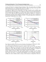
The tests have been performed for four different densities of the grid and 4 different interpo-
lation methods. It was concluded that the density of the grid is the important factor, neverthe-
less, it can be compensated by using RBF interpolation which gives good results also for sparse
grids. For example, the tri-linear interpolation on the dense grid (d
G
= 6.667 mm) results in
relative mean error below 1%, which is roughly the same as the results obtained by the RBF
cubic interpolation on the sparse grid (d
G
= 20 mm). Similar results were obtained also w.r.t.
the maximum errors: tri-linear interpolation on the dense grid results in maximum relative
error achieving 30%, whereas the RBF interpolation on the coarse grid results in maximum
relative error under 20%.
The second part of the testing focused on the precomputation phase. Here, the behaviour
of the distributed algorithm was studied w. r.t. the scalability and speed-up. It was shown
that the algorithm scales almost linearly for 4, 8, 16, 32 and 64 solver processes in the pool.
Furthermore, the experiments with geographically distributed environment were performed
using two clusters being located more than 300km from each other. It was confirmed that the
algorithm is resistant to latencies as the scalability was not affected by the distance between
the two clusters. Finally, the total length of the computations was studied. The cubic com-
plexity of the computations w. r.t. the resolution of the grid G was confirmed. Nevertheless,
it was shown that also for detailed models, the precomputation can be done in time which is
acceptable. For example, using the cluster with 64 CPUs, the construction of the configuration
space on grid with 14146 grid points (d
G
= 6.667 mm) took less than 3 hours for a model with
10270 elements employing the Mooney-Rivlin material with incompressibility conditions. For
the comparison, construction of the space for grid with 514 nodes (d
G
= 20mm) using the
same mesh and model took less than 30 minutes.
The quantitative evaluation and detailed discussion of the results obtained for the method
presented in this chapter can be find in Peterlík (2009); Peterlík et al. (2010), where also the
convergence analyses for various materials, boundary conditions and loading paths are in-
vestigated.
So far, the tests have been performed for the single-point interaction, since in that case, only
the flat 3D grid is constructed during the off-line phase. It is clear, that other types of the
interpolation can be considered, however, at the cost of increased computational complexity:
in the case of multiple-point interaction, each degree of freedom yields additional dimension
of the grid, whereas the probe interaction introduces additional levels for each grid point. In
each case, the number of transitions that must be constructed to traverse the entire configu-
ration space increases rapidly. Therefore, a modification of the approach has been presented
in Filipoviˇc et al. (2009). The configuration space is not constructed in advance in a separated
phase, however, the new configurations are generated directly during the real-time interac-
tion. The “on-line” version of the space construction assumes the haptic interaction point to
be connected to sufficient computational resources such as cluster or grid and it introduces
some restrictions concerning the maximum speed of the haptic device during the interaction.
On the other side, the time-consuming precomputation phase is not needed anymore and
therefore, more complex versions of the grid (additional dimensions and levels) can be con-
sidered. A preliminary evaluation of the on-line generation of configuration spaces can be
found in Peterlík & Filipoviˇc (2010).
4. Conclusions
In this chapter, we focused on haptic rendering of objects with complex behaviour. The study
aimed at deformable bodies which are difficult to model in real-time, provided realistic and
physically-based simulation of deformations is desired as in the case of surgical simulators.
First, a short overview of the simulation methods was given, emphasizing the computational
complexity of the calculations. The two sources of the non-linearity that emerge in the defor-
mation modeling were briefly described and the effect of the linearization was shown. Then,
a survey of methods proposed over the last decade was given: it was shown that the precom-
putation usually plays an important role in design of algorithms combining computationally
demanding calculations and real-time response. The key concepts used to overcome the high
refresh rate needed for stable haptic rendering were described separately for linear and non-
linear models.
In the second part of the chapter, the approach based on the precomputation of the configu-
ration spaces was described. First, the haptic setting was introduced for single-point, multi-
point and probe interactions. After introducing the notion of configuration and transition, it
was shown that interaction with the deformable objects can be regarded as traveling through
configuration spaces. The discretization of such spaces was proposed together with corre-
sponding algorithms for its construction and approximation. The feasibility of the approach
HapticInteractionwithComplexModelsBasedonPrecomputations 353
As shown above, polynomial as well as the RBF interpolation can be explored in the on-line
phase of the scheme to approximate the actual configuration in real-time using the precom-
puted data. In the following section, some details concerning the implementation and evalu-
ation of the algorithms presented before are given.
3.4 Evaluation and Discussion
In our prototype implementation, both the scheduler and pool of the solvers were imple-
mented in C++ programming language. The communication between the remote processes
was provided by Message-Passing Interface (MPICH implementation ver. 1.2.7 communicat-
ing over sockets). The configurations represented by the various deformation of the object
were using using GetFEM, an open-source FEM library. The solution of the linearized system
computed in each iteration of the Newton-Raphson method was performed by MUMPS lin-
ear solver (see P.R.Amestoy et al. (2000)). Further, the force interpolator was implemented
for the interpolation techniques presented in section 3.3. The interpolation of the forces was
stably running at a frequency of 1,000 Hz on a workstation equipped with 2
× Dual Core AMD
Opteron 285 processor. Similarly, precomputed nodal displacements were utilized by shape
interpolator computing the actual deformation of the body for the visualization purposes run-
ning at 25 Hz.
The experiments evaluated in the next part of this section were performed on 3D model
of human liver obtained from the INRIA repositories. The model was meshed by TetGEN
mesh generation tool resulting in two meshes with 1777 elements (501 nodes) and 10280 el-
ements (2011 nodes), respectively. The real length of the model was about 22cm. We use
both Mooney-Rivlin and StVenant-Kirchhoff material laws; in the case of Mooney-Rivlin, the
incompressibility conditions were imposed by mixed formulation.
Extensive testing has been performed to validate the approach based on the precomputation
of the configuration spaces. The evaluation can be divided into two parts as follows. First, the
accuracy of the methods has been studied. For this purpose, a large number of configurations
has been computed and stored for a random values of the positional data. The approximated
counterparts have been generated by the interpolation of the precomputed spaces, the forces
and displacements have been compared and evaluated. The mean and maximum errors have
been calculated using the large set of computed data as shown in Peterlík & Matyska (2008).
The tests have been performed for four different densities of the grid and 4 different interpo-
lation methods. It was concluded that the density of the grid is the important factor, neverthe-
less, it can be compensated by using RBF interpolation which gives good results also for sparse
grids. For example, the tri-linear interpolation on the dense grid (d
G
= 6.667 mm) results in
relative mean error below 1%, which is roughly the same as the results obtained by the RBF
cubic interpolation on the sparse grid (d
G
= 20 mm). Similar results were obtained also w.r.t.
the maximum errors: tri-linear interpolation on the dense grid results in maximum relative
error achieving 30%, whereas the RBF interpolation on the coarse grid results in maximum
relative error under 20%.
The second part of the testing focused on the precomputation phase. Here, the behaviour
of the distributed algorithm was studied w. r.t. the scalability and speed-up. It was shown
that the algorithm scales almost linearly for 4, 8, 16, 32 and 64 solver processes in the pool.
Furthermore, the experiments with geographically distributed environment were performed
using two clusters being located more than 300km from each other. It was confirmed that the
algorithm is resistant to latencies as the scalability was not affected by the distance between
the two clusters. Finally, the total length of the computations was studied. The cubic com-
plexity of the computations w. r.t. the resolution of the grid G was confirmed. Nevertheless,
it was shown that also for detailed models, the precomputation can be done in time which is
acceptable. For example, using the cluster with 64 CPUs, the construction of the configuration
space on grid with 14146 grid points (d
G
= 6.667 mm) took less than 3 hours for a model with
10270 elements employing the Mooney-Rivlin material with incompressibility conditions. For
the comparison, construction of the space for grid with 514 nodes (d
G
= 20mm ) using the
same mesh and model took less than 30 minutes.
The quantitative evaluation and detailed discussion of the results obtained for the method
presented in this chapter can be find in Peterlík (2009); Peterlík et al. (2010), where also the
convergence analyses for various materials, boundary conditions and loading paths are in-
vestigated.
So far, the tests have been performed for the single-point interaction, since in that case, only
the flat 3D grid is constructed during the off-line phase. It is clear, that other types of the
interpolation can be considered, however, at the cost of increased computational complexity:
in the case of multiple-point interaction, each degree of freedom yields additional dimension
of the grid, whereas the probe interaction introduces additional levels for each grid point. In
each case, the number of transitions that must be constructed to traverse the entire configu-
ration space increases rapidly. Therefore, a modification of the approach has been presented
in Filipoviˇc et al. (2009). The configuration space is not constructed in advance in a separated
phase, however, the new configurations are generated directly during the real-time interac-
tion. The “on-line” version of the space construction assumes the haptic interaction point to
be connected to sufficient computational resources such as cluster or grid and it introduces
some restrictions concerning the maximum speed of the haptic device during the interaction.
On the other side, the time-consuming precomputation phase is not needed anymore and
therefore, more complex versions of the grid (additional dimensions and levels) can be con-
sidered. A preliminary evaluation of the on-line generation of configuration spaces can be
found in Peterlík & Filipoviˇc (2010).
4. Conclusions
In this chapter, we focused on haptic rendering of objects with complex behaviour. The study
aimed at deformable bodies which are difficult to model in real-time, provided realistic and
physically-based simulation of deformations is desired as in the case of surgical simulators.
First, a short overview of the simulation methods was given, emphasizing the computational
complexity of the calculations. The two sources of the non-linearity that emerge in the defor-
mation modeling were briefly described and the effect of the linearization was shown. Then,
a survey of methods proposed over the last decade was given: it was shown that the precom-
putation usually plays an important role in design of algorithms combining computationally
demanding calculations and real-time response. The key concepts used to overcome the high
refresh rate needed for stable haptic rendering were described separately for linear and non-
linear models.
In the second part of the chapter, the approach based on the precomputation of the configu-
ration spaces was described. First, the haptic setting was introduced for single-point, multi-
point and probe interactions. After introducing the notion of configuration and transition, it
was shown that interaction with the deformable objects can be regarded as traveling through
configuration spaces. The discretization of such spaces was proposed together with corre-
sponding algorithms for its construction and approximation. The feasibility of the approach
AdvancesinHaptics354
was briefly sketched summarizing the main results of the extensive evaluation. Finally, the on-
line version of the algorithm was briefly discussed, showing the direction of further research
towards more complex types of interaction between the user and deformable body.
The development in the area of the soft tissues foreshadows that precomputation can still
play an important role in the haptic rendering of complex objects. Nevertheless, the algo-
rithms based on direct on-line computations are becoming still more and more attractive, as
they allow for flexible modification of the model parameters during the interaction without
necessity to recompute the data. The design of such algorithms is also encouraged by the ad-
vent of powerful accelerators such as GPGPUs, which significantly increases the performance
of single workstation that can be now used for expensive numerical calculations. Therefore, it
is possible to conclude that the physically-based deformation modeling in combination with
haptic rendering is a promising area where a sharp increase in the quality of simulation can
be expected. This will mainly concern the design of visco-elastic materials being in accor-
dance with in vitro experiments, heterogeneous models describing the internal structure of
the organs, advanced contact modeling considering the interaction between the organs, more
precise FE approximations using the meshes composed of large number of special elements,
advanced techniques allowing operations such as cutting, tearing or burning the tissue and
others.
5. References
Allard, J., Cotin, S., Faure, F., Bensoussan, P J., Poyer, F., Duriez, C., Delingette, H. & Grisoni,
L. (2007). Sofa an open source framework for medical simulation, Medicine Meets
Virtual Reality (MMVR’15), Long Beach, USA.
Barbiˇc, J. & James, D. L. (2005). Real-time subspace integration for st. venant-kirchhoff de-
formable models, SIGGRAPH ’05: ACM SIGGRAPH 2005 Papers, ACM, New York,
NY, USA, pp. 982–990.
Barbiˇc, J. & James, D. L. (2008). Six-dof haptic rendering of contact between geometrically
complex reduced deformable models, IEEE Trans. Haptics 1(1): 39–52.
Bro-Nielsen, M. (1996). Medical Image Registration and Surgery Simulation, PhD thesis, IMM
Technical University of Denmark.
Bro-Nielsen, M. & Cotin, S. (1996). Real-time volumetric deformable models for surgery simu-
lation using finite elements and condensation, Computer Graphics Forum 15(3): 57–66.
Chai, J., Sun, J. & Tang, Z. (2001). Hybrid fem for deformation of soft tissues in surgery
simulation, MIAR ’01: Proceedings of the International Workshop on Medical Imaging and
Augmented Reality (MIAR ’01), IEEE Computer Society, Washington, DC, USA, p. 298.
Ciarlet, P. G. (1988). Mathematical Elasticity: Three-dimensional elasticity, Elsevier Science Ltd.
Comas, O., Taylor, Z. A., Allard, J., Ourselin, S., Cotin, S. & Passenger, J. (2008). Efficient
nonlinear fem for soft tissue modelling and its gpu implementation within the open
source framework sofa, ISBMS ’08: Proceedings of the 4th international symposium on
Biomedical Simulation, Springer-Verlag, Berlin, Heidelberg, pp. 28–39.
Cotin, S., Delingette, H. & Ayache, N. (1996). Real time volumetric deformable models for
surgery simulation, VBC, pp. 535–540.
Cotin, S., Delingette, H. & Ayache, N. (1999). Real-time elastic deformations of soft tissues for
surgery simulation, IEEE Transactions On Visualization and Computer Graphics 5(1): 62–
73.
Cotin, S., Delingette, H. & Ayache, N. (2000a). A hybrid elastic model allowing real-time
cutting, deformations and force-feedback for surgery training and simulation, The
Visual Computer 16(8): 437–452.
Cotin, S., Delingette, H. & Ayache, N. (2000b). A hybrid elastic model allowing real-time
cutting, deformations and force-feedback for surgery training and simulation, The
Visual Computer 16(8): 437–452.
De, S., Lim, Y J., Manivannan, M. & Srinivasan, M. A. (2006). Physically realistic virtual
surgery using the point-associated finite field (paff) approach, Presence: Teleoper. Vir-
tual Environ. 15(3): 294–308.
Debunne, G., Desbrun, M., Cani, M P. & Barr, A. H. (2001). Dynamic real-time deformations
using space & time adaptive sampling, SIGGRAPH ’01: Proceedings of the 28th annual
conference on Computer graphics and interactive techniques, ACM, New York, NY, USA,
pp. 31–36.
Delingette, H. & Ayache, N. (2005). Hepatic surgery simulation, Commun. ACM 48(2): 31–36.
Deo, D. & De, S. (2009). Phyness: A physics-driven neural networks-based surgery simulation
system with force feedback, World Haptics Conference 0: 30–34.
Filipoviˇc, J., Peterlík, I. & Matyska, L. (2009). On-line precomputation algorithm for real-time
haptic interaction with non-linear deformable bodies, Proceedings of The Third Joint
EuroHaptics Conference and Symposium on Haptic Interfaces for Virtual Environments and
Teleoperator Systems, pp. 24–29.
Frank, A. O., A.Twombly, I., Barth, T. J. & Smith, J. D. (2001). Finite element methods for real-
time haptic feedback of soft-tissue models in virtual reality simulators, VR ’01: Pro-
ceedings of the Virtual Reality 2001 Conference (VR’01), IEEE Computer Society, Wash-
ington, DC, USA, p. 257.
Gosline, A. H., Salcudean, S. E. & Yan, J. (2004). Haptic simulation of linear elastic media
with fluid pockets, Haptic Interfaces for Virtual Environment and Teleoperator Systems,
International Symposium on 0: 266–271.
Hager, W. W. (1989). Updating the inverse of a matrix, SIAM Rev. 31(2): 221–239.
James, D. & Pai, D. (2002). Real time simulation of multizone elastokinematic models, Inter-
national Conference on Robotics and Automation, Washington, D.C., USA, pp. 927–932.
J.T.Oden (1972). Finite Elements of Non-linear Continua, McGraw-Hill.
Kˇrenek, A. (2003). Haptic rendering of complex force fields, EGVE ’03: Proceedings of the
workshop on Virtual environments 2003, ACM, pp. 231–239.
Miller, K., Joldes, G., Lance, D. & Wittek, A. (2007). Total lagrangian explicit dynamics finite el-
ement algorithm for computing soft tissue deformation, Communications in Numerical
Methods in Engineering 23(2): 121–134.
Misra, S., Okamura, A. M. & Ramesh, K. T. (2007). Force feedback is noticeably different for
linear versus nonlinear elastic tissue models, WHC ’07: Proceedings of the Second Joint
EuroHaptics Conference and Symposium on Haptic Interfaces for Virtual Environment and
Teleoperator Systems, IEEE Computer Society, Washington, DC, USA, pp. 519–524.
Nikitin, I., Nikitina, L., Frolov, P., Goebbels, G., Göbel, M., Klimenko, S. & Nielson, G. M.
(2002). Real-time simulation of elastic objects in virtual environments using finite el-
ement method and precomputed green’s functions, EGVE ’02: Proceedings of the work-
shop on Virtual environments 2002, Eurographics Association, Aire-la-Ville, Switzer-
land, Switzerland, pp. 47–52.
Peterlík, I. (2008). Efficient precomputation of configuration space for haptic deforma-
tion modeling, Proceedings of Conference on Human System Interactions, IEEE Xplore,
pp. 225–230. best paper award.
Peterlík, I. (2009). Haptic Interaction with non-linear deformable objects, PhD thesis, Masaryk
University.
HapticInteractionwithComplexModelsBasedonPrecomputations 355
was briefly sketched summarizing the main results of the extensive evaluation. Finally, the on-
line version of the algorithm was briefly discussed, showing the direction of further research
towards more complex types of interaction between the user and deformable body.
The development in the area of the soft tissues foreshadows that precomputation can still
play an important role in the haptic rendering of complex objects. Nevertheless, the algo-
rithms based on direct on-line computations are becoming still more and more attractive, as
they allow for flexible modification of the model parameters during the interaction without
necessity to recompute the data. The design of such algorithms is also encouraged by the ad-
vent of powerful accelerators such as GPGPUs, which significantly increases the performance
of single workstation that can be now used for expensive numerical calculations. Therefore, it
is possible to conclude that the physically-based deformation modeling in combination with
haptic rendering is a promising area where a sharp increase in the quality of simulation can
be expected. This will mainly concern the design of visco-elastic materials being in accor-
dance with in vitro experiments, heterogeneous models describing the internal structure of
the organs, advanced contact modeling considering the interaction between the organs, more
precise FE approximations using the meshes composed of large number of special elements,
advanced techniques allowing operations such as cutting, tearing or burning the tissue and
others.
5. References
Allard, J., Cotin, S., Faure, F., Bensoussan, P J., Poyer, F., Duriez, C., Delingette, H. & Grisoni,
L. (2007). Sofa an open source framework for medical simulation, Medicine Meets
Virtual Reality (MMVR’15), Long Beach, USA.
Barbiˇc, J. & James, D. L. (2005). Real-time subspace integration for st. venant-kirchhoff de-
formable models, SIGGRAPH ’05: ACM SIGGRAPH 2005 Papers, ACM, New York,
NY, USA, pp. 982–990.
Barbiˇc, J. & James, D. L. (2008). Six-dof haptic rendering of contact between geometrically
complex reduced deformable models, IEEE Trans. Haptics 1(1): 39–52.
Bro-Nielsen, M. (1996). Medical Image Registration and Surgery Simulation, PhD thesis, IMM
Technical University of Denmark.
Bro-Nielsen, M. & Cotin, S. (1996). Real-time volumetric deformable models for surgery simu-
lation using finite elements and condensation, Computer Graphics Forum 15(3): 57–66.
Chai, J., Sun, J. & Tang, Z. (2001). Hybrid fem for deformation of soft tissues in surgery
simulation, MIAR ’01: Proceedings of the International Workshop on Medical Imaging and
Augmented Reality (MIAR ’01), IEEE Computer Society, Washington, DC, USA, p. 298.
Ciarlet, P. G. (1988). Mathematical Elasticity: Three-dimensional elasticity, Elsevier Science Ltd.
Comas, O., Taylor, Z. A., Allard, J., Ourselin, S., Cotin, S. & Passenger, J. (2008). Efficient
nonlinear fem for soft tissue modelling and its gpu implementation within the open
source framework sofa, ISBMS ’08: Proceedings of the 4th international symposium on
Biomedical Simulation, Springer-Verlag, Berlin, Heidelberg, pp. 28–39.
Cotin, S., Delingette, H. & Ayache, N. (1996). Real time volumetric deformable models for
surgery simulation, VBC, pp. 535–540.
Cotin, S., Delingette, H. & Ayache, N. (1999). Real-time elastic deformations of soft tissues for
surgery simulation, IEEE Transactions On Visualization and Computer Graphics 5(1): 62–
73.
Cotin, S., Delingette, H. & Ayache, N. (2000a). A hybrid elastic model allowing real-time
cutting, deformations and force-feedback for surgery training and simulation, The
Visual Computer 16(8): 437–452.
Cotin, S., Delingette, H. & Ayache, N. (2000b). A hybrid elastic model allowing real-time
cutting, deformations and force-feedback for surgery training and simulation, The
Visual Computer 16(8): 437–452.
De, S., Lim, Y J., Manivannan, M. & Srinivasan, M. A. (2006). Physically realistic virtual
surgery using the point-associated finite field (paff) approach, Presence: Teleoper. Vir-
tual Environ. 15(3): 294–308.
Debunne, G., Desbrun, M., Cani, M P. & Barr, A. H. (2001). Dynamic real-time deformations
using space & time adaptive sampling, SIGGRAPH ’01: Proceedings of the 28th annual
conference on Computer graphics and interactive techniques, ACM, New York, NY, USA,
pp. 31–36.
Delingette, H. & Ayache, N. (2005). Hepatic surgery simulation, Commun. ACM 48(2): 31–36.
Deo, D. & De, S. (2009). Phyness: A physics-driven neural networks-based surgery simulation
system with force feedback, World Haptics Conference 0: 30–34.
Filipoviˇc, J., Peterlík, I. & Matyska, L. (2009). On-line precomputation algorithm for real-time
haptic interaction with non-linear deformable bodies, Proceedings of The Third Joint
EuroHaptics Conference and Symposium on Haptic Interfaces for Virtual Environments and
Teleoperator Systems, pp. 24–29.
Frank, A. O., A.Twombly, I., Barth, T. J. & Smith, J. D. (2001). Finite element methods for real-
time haptic feedback of soft-tissue models in virtual reality simulators, VR ’01: Pro-
ceedings of the Virtual Reality 2001 Conference (VR’01), IEEE Computer Society, Wash-
ington, DC, USA, p. 257.
Gosline, A. H., Salcudean, S. E. & Yan, J. (2004). Haptic simulation of linear elastic media
with fluid pockets, Haptic Interfaces for Virtual Environment and Teleoperator Systems,
International Symposium on 0: 266–271.
Hager, W. W. (1989). Updating the inverse of a matrix, SIAM Rev. 31(2): 221–239.
James, D. & Pai, D. (2002). Real time simulation of multizone elastokinematic models, Inter-
national Conference on Robotics and Automation, Washington, D.C., USA, pp. 927–932.
J.T.Oden (1972). Finite Elements of Non-linear Continua, McGraw-Hill.
Kˇrenek, A. (2003). Haptic rendering of complex force fields, EGVE ’03: Proceedings of the
workshop on Virtual environments 2003, ACM, pp. 231–239.
Miller, K., Joldes, G., Lance, D. & Wittek, A. (2007). Total lagrangian explicit dynamics finite el-
ement algorithm for computing soft tissue deformation, Communications in Numerical
Methods in Engineering 23(2): 121–134.
Misra, S., Okamura, A. M. & Ramesh, K. T. (2007). Force feedback is noticeably different for
linear versus nonlinear elastic tissue models, WHC ’07: Proceedings of the Second Joint
EuroHaptics Conference and Symposium on Haptic Interfaces for Virtual Environment and
Teleoperator Systems, IEEE Computer Society, Washington, DC, USA, pp. 519–524.
Nikitin, I., Nikitina, L., Frolov, P., Goebbels, G., Göbel, M., Klimenko, S. & Nielson, G. M.
(2002). Real-time simulation of elastic objects in virtual environments using finite el-
ement method and precomputed green’s functions, EGVE ’02: Proceedings of the work-
shop on Virtual environments 2002, Eurographics Association, Aire-la-Ville, Switzer-
land, Switzerland, pp. 47–52.
Peterlík, I. (2008). Efficient precomputation of configuration space for haptic deforma-
tion modeling, Proceedings of Conference on Human System Interactions, IEEE Xplore,
pp. 225–230. best paper award.
Peterlík, I. (2009). Haptic Interaction with non-linear deformable objects, PhD thesis, Masaryk
University.
AdvancesinHaptics356
Peterlík, I. & Filipoviˇc, J. (2010). Distributed construction of configuration spaces for real-time
haptic deformation modeling, IEEE Transactions on Industrial Electronics p. to appear.
Peterlík, I. & Matyska, L. (2008). Haptic interaction with soft tissues based on state-space ap-
proximation, EuroHaptics ’08: Proceedings of the 6th international conference on Haptics,
Springer-Verlag, Berlin, Heidelberg, pp. 886–895.
Peterlík, I., Sedef, M., Basdogan, C. & Matyska, L. (2010). Real-time visio-haptic interaction
with static soft tissue models having geometric and material nonlinearity, Computers
& Graphics p. to appear.
Picinbono, G., Delingette, H. & Ayache, N. (2001). Non-linear and anisotropic elastic soft tissue
models for medical simulation, ICRA2001: IEEE International Conference Robotics and
Automation, Seoul Korea. 6 pages.
Picinbono, G., Delingette, H. & Ayache, N. (2003). Non-linear anisotropic elasticity for real-
time surgery simulation, Graphical Models 65(5): 305–321.
Picinbono, G., Lombardo, J C., Delingette, H. & Ayache, N. (2002). Improving realism of
a surgery simulator: linear anisotropic elasticity, complex interactions and force ex-
trapolation, Journal of Visualisation and Computer Animation 13(3): 147–167.
Popescu, D. C. & Compton, M. (2003). A model for efficient and accurate interaction with
elastic objects in haptic virtual environments, GRAPHITE ’03: Proceedings of the 1st
international conference on Computer graphics and interactive techniques in Australasia and
South East Asia, ACM Press, New York, NY, USA, pp. 245–250.
P.R.Amestoy, I.S.Duff & L’Excellent, J Y. (2000). Multifrontal parallel distributed symmetric
and unsymmetric solvers, Comput. Methods in Appl. Mech. Eng. 184: 501–520.
Saupin, G., Duriez, C., Cotin, S. & Grisoni, L. (2008). Efficient contact modeling using compli-
ance warping, Computer Graphics International Conference (CGI) Istambul, Turkey,.
Sedef, M., Samur, E. & Basdogan, C. (2006). Real-time finite-element simulation of linear
viscoelastic tissue behavior based on experimental data, IEEE Comput. Graph. Appl.
26(6): 58–68.
Taylor, M., Cheng, M. & Ourselin, S. (2007). Real-time nonlinear finite element analysis
for surgical simulation using graphics processing units, Medical Image Computing &
Computer-Assisted Intervention Conference, pp. 701–708.
Wriggers, P. (2008). Nonlinear Finite Element Methods, 2008 Springer Verlag.
Wu, X., Downes, M. S., Goktekin, T. & Tendick, F. (2001). Adaptive nonlinear finite elements
for deformable body simulation using dynamic progressive meshes, in A. Chalmers
& T M. Rhyne (eds), EG 2001 Proceedings, Vol. 20(3), Blackwell Publishing, pp. 349–
358.
Wu, X., Goktekin, T. & Tendick, F. (2004). An interactive parallel multigrid fem simulator,
ISMS, pp. 124–133.
Wu, X. & Tendick, F. (2004). Multigrid integration for interactive deformable body simula-
tion, International Symposium on Medical Simulation (2004).Association for Computing
Machinery, Inc, pp. 92–104.
Zhuang, Y. (2000). Real-time simulation of physically realistic global deformations, PhD thesis,
Department of Electrical Engineering and Computer Science, UC Berkeley. Chair-
John Canny.
Zhuang, Y. & Canny, J. (1999). Real-time simulation of physically realistic global deformation,
IEEE Vis’99 Late Breaking Hot Topics.
Zhuang, Y. & Canny, J. (2000). Real-time global deformations, The fourth International Workshop
on Algorithmic Foundations of Robotics (WAFR), A. K. Peters, pp. 97–107.
AHapticModelingSystem 357
AHapticModelingSystem
JehaRyuandHyungonKim
X
A Haptic Modeling System
Jeha Ryu and Hyungon Kim
Haptics Lab
Gwangju Institute of Science and Technology, KOREA
E-mail: { ryu, hyungonkim}@gist.ac.kr
Abstract
Haptics has been studied as a means of providing users with natural and immersive haptic
sensations in various real, augmented, and virtual environments, but it is still relatively
unfamiliar to the general public. One reason is the lack of abundant haptic content in areas
familiar to the general public. Even though some modeling tools do exist for creating haptic
content, the addition of haptic data to graphic models is still relatively primitive, time
consuming, and unintuitive. In order to establish a comprehensive and efficient haptic
modeling system, this chapter first defines the haptic modeling processes and its scopes. It
then proposes a haptic modeling system that can, based on depth images and image data
structure, create and edit haptic content easily and intuitively for virtual object. This system
can also efficiently handle non-uniform haptic property per pixel, and can effectively
represent diverse haptic properties (stiffness, friction, etc).
Keywords – haptics, haptic modeling, virtual reality, augmented reality, depth image
1. Introduction
Haptics has been studied as a means of providing users with natural and immersive
sensations of digital content in the fields of medicine [1], education [2], entertainment [3],
and broadcasting [4]. Haptic interfaces allow users to touch, explore, and manipulate 3D
objects in an intuitive way with realistic haptic feedback and can be applied to create touch-
enabled solutions that improve learning, understanding, creativity and communication. In
spite of the considerable advantages, however, haptics is still largely unfamiliar to most
people, potentially due to the lack of abundant haptic interaction contents in areas of
interest to the general public. Audiovisual content, on the other hand, is readily available to
the general public in a variety of forms, including movies and music, because it can easily be
captured using a camera or microphone and can be created by a wide range of modeling
and authoring tools. Haptic content, on the other hand, has not yet reached this ease of use,
as there are not many haptic cameras or microphones available and still relatively few
easily-useable modeling and authoring tools for creating haptic content.
In the meantime, there are a few tools providing a graphic modeling system with force
feedback in the 3D geometric model design process, including geometric modeling,
18
AdvancesinHaptics358
sculpturing, and painting. Among them, Freeform [5] and ClayTools
TM
[6] are virtual
modeling and sculpturing systems that have been commercialized by SensAble
Technologies. InTouch [7] and ArtNova [8] are touch-enabled 3D painting and multi-
resolution modeling systems, and dAb [9] is a haptic painting system with 3D deformable
brushes. These systems, however, use haptic technology purely as an assistant tool for
effective and intuitive geometric modeling, sculpturing, and painting. Therefore, these tools
cannot exactly be considered to be the haptic modeling tools according to the definitions
and scopes in the following section.
Despite their lack of recognition, though, there are a few haptics-based application systems
currently in use. FLIGHT GHUI Builder (FGB) [10] and REACHIN [11] Application
Programming Interface (API) are both platforms that enable the development of haptic
content. FGB is a tool designed specifically for the creation of graphic and haptic user, while
REACHIN API is used to develop sophisticated haptic 3D applications and to provide
functionalities when editing haptic data. By providing users with a set of haptic/graphic
libraries and some haptics-related editing functions in haptic APIs, as in OpenHaptics
Toolkit [12] and CHAI3D [13], it is possible to construct application specific haptic models.
Tempkin et al. [14] proposed a haptic modeling system called web-based three dimensional
virtual body structure (W3D-VBS). This software provides editing functions for haptic
properties and can edit a variety of haptic surface properties including stiffness, friction, and
damping for tissue palpation. Seo et al. [15] also proposed a haptic modeling system called
K-Haptic Modeler
TM
, which provides editing functions for haptic properties by using the K-
Touch
TM
Haptic Application Programming Interface (API) [16] to support the haptic user
interface. Eid et al. [17] further suggested a haptic modeling system called HAMLAT in
which the authoring tool is composed of the HAMLAT editor, the HAML engine, and a
rendering engine.
Most haptic modeling systems, including HAMLAT, OpenHaptics, and K-Haptic
Modeler
TM
, are either object or polygon-based: In the object-based modeling system, the
haptic properties are applied on a whole object, while in the polygon-based system, they are
applied on some parts of an object. It is therefore difficult to edit non-uniform haptic
properties on only part of a surface or object. Thus, instead of applying global properties to
a model, as in the object-or polygon-based approach, Kim et al. [18, 19] proposed a haptic
decoration and local material editing system for enhancing the haptic realism of a virtual
object. This system allows a user to paint directly on to the surface of a 3D object and to
locally edit and feel haptic material properties (stiffness, friction) in a natural way.
Haptic content typically consists of computer graphic models, created using a general
graphic modeler such as MAYA or 3D MAX, with the subsequent addition of haptic data. In
graphic modeling, graphic content is created while the quality of work is directly verified
visually. Therefore, in order to create a variety of diverse and naturally feeling haptic
content, it is necessary to develop haptic modelers which are user-friendly, easy-to-use,
general purpose, and efficient. The modeling software and applications must provide
sufficient graphic/haptic functionality in the modeling processes, which can then provide
on-line feedback of the edited haptic material properties in real time as users edit on the
surface of an object. Moreover, the haptic modelers must have ample speed and memory-
efficiency to ensure high productivity and to be economical.
The rest of this chapter is organized as follows. Section 2 defines the haptic modeling
processes systematically and comprehensively and then summarizes their scopes. A depth
image-based haptic modeling algorithm is then proposed for editing non-uniform and
diverse haptic properties on the surface of a virtual object in Section 3. This proposed
method stores haptic property values into six orthogonal image data structures, called
haptic property images, to more efficiently and cost-effectively represent a more realistic
feeling of touch. Section 4 suggests a basic framework for a haptic modeling system (a
modified K-HapticModeler
TM
) that can create and edit haptic content for virtual objects. The
final section provides conclusions and suggests future research items to improve the
proposed modeling functions.
2. Haptic Modeling: defintion and scope
A. Definition of Haptic Modeling
There seems to be no formal comprehensive definition of haptic modeling and its scope,
although there are many techniques for digital sculpting or performing geometric modeling
with a force sensation that can be evoked by some sort of haptic device. We define haptic
modeling more formally and comprehensively as follows:
Definition: Haptic modeling is a series of processes to create haptic content on graphic models that
are components of virtual reality (VR), augmented reality (AR), or mixed reality (MR).
B. Scope of Haptic Modeling
The haptic modeling processes as a whole consist basically of four smaller processes: (i)
acquiring haptic data and the subsequent signal/image processing, as well as data
management to acquire haptic data from the physical world, (ii) geometric processing to
preprocess graphic models, (iii) haptic processing to edit or to author haptic data onto a
graphic model, and (iv) haptic modeling to add haptic effects into the overall graphic
environment. Here, haptic data may include not only material properties (stiffness and
friction), haptic texture (roughness), and force/torque histories, but also motion trajectories
such as time histories of acceleration, velocity, and position. Figure 1 shows the scope of the
proposed haptic modeling processes.
Fig. 1. Scope of Haptic Modeling Processes
a. Acquiring Haptic Data
There are two processes in the acquisition stage of haptic data; (i) the acquisition of haptic
data (including signal processing to get true haptic data from noisy raw signals) from the
physical world through either a sensing systems or a mathematical modeling technique, and
(ii) the construction of a haptic database.
To build realistic haptic contents, haptic data must first be acquired from the real world.
Surface material properties (stiffness and friction), haptic texture (roughness), and force
AHapticModelingSystem 359
sculpturing, and painting. Among them, Freeform [5] and ClayTools
TM
[6] are virtual
modeling and sculpturing systems that have been commercialized by SensAble
Technologies. InTouch [7] and ArtNova [8] are touch-enabled 3D painting and multi-
resolution modeling systems, and dAb [9] is a haptic painting system with 3D deformable
brushes. These systems, however, use haptic technology purely as an assistant tool for
effective and intuitive geometric modeling, sculpturing, and painting. Therefore, these tools
cannot exactly be considered to be the haptic modeling tools according to the definitions
and scopes in the following section.
Despite their lack of recognition, though, there are a few haptics-based application systems
currently in use. FLIGHT GHUI Builder (FGB) [10] and REACHIN [11] Application
Programming Interface (API) are both platforms that enable the development of haptic
content. FGB is a tool designed specifically for the creation of graphic and haptic user, while
REACHIN API is used to develop sophisticated haptic 3D applications and to provide
functionalities when editing haptic data. By providing users with a set of haptic/graphic
libraries and some haptics-related editing functions in haptic APIs, as in OpenHaptics
Toolkit [12] and CHAI3D [13], it is possible to construct application specific haptic models.
Tempkin et al. [14] proposed a haptic modeling system called web-based three dimensional
virtual body structure (W3D-VBS). This software provides editing functions for haptic
properties and can edit a variety of haptic surface properties including stiffness, friction, and
damping for tissue palpation. Seo et al. [15] also proposed a haptic modeling system called
K-Haptic Modeler
TM
, which provides editing functions for haptic properties by using the K-
Touch
TM
Haptic Application Programming Interface (API) [16] to support the haptic user
interface. Eid et al. [17] further suggested a haptic modeling system called HAMLAT in
which the authoring tool is composed of the HAMLAT editor, the HAML engine, and a
rendering engine.
Most haptic modeling systems, including HAMLAT, OpenHaptics, and K-Haptic
Modeler
TM
, are either object or polygon-based: In the object-based modeling system, the
haptic properties are applied on a whole object, while in the polygon-based system, they are
applied on some parts of an object. It is therefore difficult to edit non-uniform haptic
properties on only part of a surface or object. Thus, instead of applying global properties to
a model, as in the object-or polygon-based approach, Kim et al. [18, 19] proposed a haptic
decoration and local material editing system for enhancing the haptic realism of a virtual
object. This system allows a user to paint directly on to the surface of a 3D object and to
locally edit and feel haptic material properties (stiffness, friction) in a natural way.
Haptic content typically consists of computer graphic models, created using a general
graphic modeler such as MAYA or 3D MAX, with the subsequent addition of haptic data. In
graphic modeling, graphic content is created while the quality of work is directly verified
visually. Therefore, in order to create a variety of diverse and naturally feeling haptic
content, it is necessary to develop haptic modelers which are user-friendly, easy-to-use,
general purpose, and efficient. The modeling software and applications must provide
sufficient graphic/haptic functionality in the modeling processes, which can then provide
on-line feedback of the edited haptic material properties in real time as users edit on the
surface of an object. Moreover, the haptic modelers must have ample speed and memory-
efficiency to ensure high productivity and to be economical.
The rest of this chapter is organized as follows. Section 2 defines the haptic modeling
processes systematically and comprehensively and then summarizes their scopes. A depth
image-based haptic modeling algorithm is then proposed for editing non-uniform and
diverse haptic properties on the surface of a virtual object in Section 3. This proposed
method stores haptic property values into six orthogonal image data structures, called
haptic property images, to more efficiently and cost-effectively represent a more realistic
feeling of touch. Section 4 suggests a basic framework for a haptic modeling system (a
modified K-HapticModeler
TM
) that can create and edit haptic content for virtual objects. The
final section provides conclusions and suggests future research items to improve the
proposed modeling functions.
2. Haptic Modeling: defintion and scope
A. Definition of Haptic Modeling
There seems to be no formal comprehensive definition of haptic modeling and its scope,
although there are many techniques for digital sculpting or performing geometric modeling
with a force sensation that can be evoked by some sort of haptic device. We define haptic
modeling more formally and comprehensively as follows:
Definition: Haptic modeling is a series of processes to create haptic content on graphic models that
are components of virtual reality (VR), augmented reality (AR), or mixed reality (MR).
B. Scope of Haptic Modeling
The haptic modeling processes as a whole consist basically of four smaller processes: (i)
acquiring haptic data and the subsequent signal/image processing, as well as data
management to acquire haptic data from the physical world, (ii) geometric processing to
preprocess graphic models, (iii) haptic processing to edit or to author haptic data onto a
graphic model, and (iv) haptic modeling to add haptic effects into the overall graphic
environment. Here, haptic data may include not only material properties (stiffness and
friction), haptic texture (roughness), and force/torque histories, but also motion trajectories
such as time histories of acceleration, velocity, and position. Figure 1 shows the scope of the
proposed haptic modeling processes.
Fig. 1. Scope of Haptic Modeling Processes
a. Acquiring Haptic Data
There are two processes in the acquisition stage of haptic data; (i) the acquisition of haptic
data (including signal processing to get true haptic data from noisy raw signals) from the
physical world through either a sensing systems or a mathematical modeling technique, and
(ii) the construction of a haptic database.
To build realistic haptic contents, haptic data must first be acquired from the real world.
Surface material properties (stiffness and friction), haptic texture (roughness), and force
AdvancesinHaptics360
profiles of haptic widgets (buttons, sliders, joypads, etc.) can be obtained through many
different kinds of physical sensors, such as a force/torque sensor to get a force/torque time
history, while a user is interacting with a real physical object (e.g. physical buttons or
sliders) or with a real physical scene (environment). A visual camera may also be used to
acquire some of the geometric details of an object surface for haptic texture modeling with
subsequent image processing.
After sensor signals are acquired, these raw signals must then be processed to derive
haptically useful data. A human perception threshold may be applied in these kinds of
processing. For button force history, for example, some identification process may be
necessary to find out onset of sudden drop of buttoning force. Motion histories can be
captured and stored by visual cameras, inertial sensors, or by motion capture systems. The
motion trajectories can also be used for describing ball trajectories and hand writing
trajectories. Haptic data may also be modeled by some mathematical functions. Regardless
of the means of acquisition, haptic data must be stored efficiently in the memory due to the
potentially large size of the dataset. Therefore, it is important to develop an efficient data
base management method.
b. Preprocessing Geometric Models
The preprocessing stage requires specific geometric processing for subsequent haptic
modeling. For instance, even though a geometric model may seem fine graphically, it may
contain many holes, gaps, or noises that have been acquired from 3D scanners, z-Cam
TM
,
MRI, CT, etc. These can be felt haptically while users explore the graphic model to receive
an unexpected haptic sensation. Therefore, these graphically-unseen-but-haptically-feelable
holes, gaps, or noises must be eliminated before any material editing process can begin.
Further preprocessing may be also necessary. In most existing haptic modeling systems, a
single set of haptic data is applied to the entire 3D model. However, users may want to
model haptic data in one local or special area. In this case, geometric processing for dividing
an object into several areas needs to be done before the haptic modeling process. Otherwise,
a new method to edit non-uniform haptic properties on the surface of a virtual object should
be developed.
c. Editing/Authoring Haptic Data
The editing or authoring of haptic data (surface material properties such as stiffness and
frictions, force profiles of haptic widgets, etc.) is a significant part of the haptic modeling
process and must be performed as intuitively and quickly as possible, similar to the
geometric modeling process.
d. Adding Haptic Effects
Aside from the editing of haptic data onto graphic models, other haptic modeling processes
also exist. For example, a gravity or electromagnetic effect may be applied in the whole
virtual worlds to simulate weight or inter-atomic interaction force sensation when a user
grabs an object or an atom (charged particle) in the gravitational or electromagnetic field.
The case of automatic motion generation for a dynamically moving system is another
example. If a soccer ball is kicked by an input action from the user and the user want to feel
the motion trajectories of the soccer ball, the ball’s motion history must be dynamically
simulated in real time by the use of numerical integration algorithms.
This chapter discusses only the modeling, more specifically, the haptic editing of graphic
objects as discussed in the above step (c). Other steps will be discussed in future
publications.
3. A Haptic modeling system
To edit 3D objects haptically, four steps are usually required. First, haptic modeling
designers select some 3D object surfaces on which they want to assign haptic property
values and, in the second step, they assign the desired haptic property values on the selected
surfaces. Third, the user checks whether the touch feeling by the modeled haptic property
values is realistic or not. If the feeling is not realistic or appropriate, they should adjust the
values on-line by simultaneously changing the values and feeling the surface. Finally, once
they are satisfied with the realistic haptic property values for the surfaces, they then store
the values and chosen surfaces in a suitable format.
Depending on the method of picking out the surfaces on which the desired haptic property
values are pasted, haptic modeling can be classified into three methods: (i) object-based, (ii)
polygon-based, and (iii) voxel-based. The object-based haptic modeling method [14, 15]
selects the entire surface of a 3D object when assigning haptic property values. Therefore,
the entire surface of an object can have only a single uniform haptic property value. A glass
bottle, for example, would have a single uniform haptic property value of stiffness, friction,
and roughness over the entire surface. Therefore, if a 3D object consists of many parts with
different haptic properties, partitioning is required in the preprocessing stage to assign
different haptic property values to different parts. The polygon-based haptic modeling
method [17] selects some parts of meshes from the whole 3D meshes comprising an object.
Therefore, each mesh can have a different haptic property value. If the number of meshes is
large for fine and non-uniform specifications of surface haptic properties, however, the size
of the haptic property data also increases. Moreover, if a haptic modeling designer wants to
model a part smaller than a mesh, subdivision is required. The object and polygon-based
haptic modeling methods, therefore, usually cause difficulty when editing non-uniform
haptic properties on the selected surfaces. On the other hand, the voxel-based haptic
modeling method [18, 19] uses the hybrid implicit and geometry surface data representation.
This method uses volumetric data representation and, therefore, in the surface selection
process, the selected surfaces need to be mapped into the voxel data. Then the voxel and a
single haptic property group that contains diverse haptic properties in a single data
structure will be stored. However, the size of the converted volumetric data into surface
data by means of a mapping function between the voxel and haptic property values is huge
because the data is structured like a hash function. It subsequently needs a large amount of
memory (order of N
3
) for modeling a very fine non-uniform haptic property.
In summary, for non-uniform haptic property modeling on surfaces of a virtual object, the
existing methods require processes that: (i) divide a virtual object into many surfaces or
component objects if a visual model consists of many components, (ii) maps between haptic
property values and graphical data sets, (iii) converts data because of the dependency on
data-representation, such as polygon and voxel. To avoid these additional processes in
modeling non-uniform haptic properties, we propose a depth image-based haptic modeling
method. In the proposed method, several two dimensional multi-layered image data
structures, called haptic property images, store non-uniform and diverse haptic property
AHapticModelingSystem 361
profiles of haptic widgets (buttons, sliders, joypads, etc.) can be obtained through many
different kinds of physical sensors, such as a force/torque sensor to get a force/torque time
history, while a user is interacting with a real physical object (e.g. physical buttons or
sliders) or with a real physical scene (environment). A visual camera may also be used to
acquire some of the geometric details of an object surface for haptic texture modeling with
subsequent image processing.
After sensor signals are acquired, these raw signals must then be processed to derive
haptically useful data. A human perception threshold may be applied in these kinds of
processing. For button force history, for example, some identification process may be
necessary to find out onset of sudden drop of buttoning force. Motion histories can be
captured and stored by visual cameras, inertial sensors, or by motion capture systems. The
motion trajectories can also be used for describing ball trajectories and hand writing
trajectories. Haptic data may also be modeled by some mathematical functions. Regardless
of the means of acquisition, haptic data must be stored efficiently in the memory due to the
potentially large size of the dataset. Therefore, it is important to develop an efficient data
base management method.
b. Preprocessing Geometric Models
The preprocessing stage requires specific geometric processing for subsequent haptic
modeling. For instance, even though a geometric model may seem fine graphically, it may
contain many holes, gaps, or noises that have been acquired from 3D scanners, z-Cam
TM
,
MRI, CT, etc. These can be felt haptically while users explore the graphic model to receive
an unexpected haptic sensation. Therefore, these graphically-unseen-but-haptically-feelable
holes, gaps, or noises must be eliminated before any material editing process can begin.
Further preprocessing may be also necessary. In most existing haptic modeling systems, a
single set of haptic data is applied to the entire 3D model. However, users may want to
model haptic data in one local or special area. In this case, geometric processing for dividing
an object into several areas needs to be done before the haptic modeling process. Otherwise,
a new method to edit non-uniform haptic properties on the surface of a virtual object should
be developed.
c. Editing/Authoring Haptic Data
The editing or authoring of haptic data (surface material properties such as stiffness and
frictions, force profiles of haptic widgets, etc.) is a significant part of the haptic modeling
process and must be performed as intuitively and quickly as possible, similar to the
geometric modeling process.
d. Adding Haptic Effects
Aside from the editing of haptic data onto graphic models, other haptic modeling processes
also exist. For example, a gravity or electromagnetic effect may be applied in the whole
virtual worlds to simulate weight or inter-atomic interaction force sensation when a user
grabs an object or an atom (charged particle) in the gravitational or electromagnetic field.
The case of automatic motion generation for a dynamically moving system is another
example. If a soccer ball is kicked by an input action from the user and the user want to feel
the motion trajectories of the soccer ball, the ball’s motion history must be dynamically
simulated in real time by the use of numerical integration algorithms.
This chapter discusses only the modeling, more specifically, the haptic editing of graphic
objects as discussed in the above step (c). Other steps will be discussed in future
publications.
3. A Haptic modeling system
To edit 3D objects haptically, four steps are usually required. First, haptic modeling
designers select some 3D object surfaces on which they want to assign haptic property
values and, in the second step, they assign the desired haptic property values on the selected
surfaces. Third, the user checks whether the touch feeling by the modeled haptic property
values is realistic or not. If the feeling is not realistic or appropriate, they should adjust the
values on-line by simultaneously changing the values and feeling the surface. Finally, once
they are satisfied with the realistic haptic property values for the surfaces, they then store
the values and chosen surfaces in a suitable format.
Depending on the method of picking out the surfaces on which the desired haptic property
values are pasted, haptic modeling can be classified into three methods: (i) object-based, (ii)
polygon-based, and (iii) voxel-based. The object-based haptic modeling method [14, 15]
selects the entire surface of a 3D object when assigning haptic property values. Therefore,
the entire surface of an object can have only a single uniform haptic property value. A glass
bottle, for example, would have a single uniform haptic property value of stiffness, friction,
and roughness over the entire surface. Therefore, if a 3D object consists of many parts with
different haptic properties, partitioning is required in the preprocessing stage to assign
different haptic property values to different parts. The polygon-based haptic modeling
method [17] selects some parts of meshes from the whole 3D meshes comprising an object.
Therefore, each mesh can have a different haptic property value. If the number of meshes is
large for fine and non-uniform specifications of surface haptic properties, however, the size
of the haptic property data also increases. Moreover, if a haptic modeling designer wants to
model a part smaller than a mesh, subdivision is required. The object and polygon-based
haptic modeling methods, therefore, usually cause difficulty when editing non-uniform
haptic properties on the selected surfaces. On the other hand, the voxel-based haptic
modeling method [18, 19] uses the hybrid implicit and geometry surface data representation.
This method uses volumetric data representation and, therefore, in the surface selection
process, the selected surfaces need to be mapped into the voxel data. Then the voxel and a
single haptic property group that contains diverse haptic properties in a single data
structure will be stored. However, the size of the converted volumetric data into surface
data by means of a mapping function between the voxel and haptic property values is huge
because the data is structured like a hash function. It subsequently needs a large amount of
memory (order of N
3
) for modeling a very fine non-uniform haptic property.
In summary, for non-uniform haptic property modeling on surfaces of a virtual object, the
existing methods require processes that: (i) divide a virtual object into many surfaces or
component objects if a visual model consists of many components, (ii) maps between haptic
property values and graphical data sets, (iii) converts data because of the dependency on
data-representation, such as polygon and voxel. To avoid these additional processes in
modeling non-uniform haptic properties, we propose a depth image-based haptic modeling
method. In the proposed method, several two dimensional multi-layered image data
structures, called haptic property images, store non-uniform and diverse haptic property
AdvancesinHaptics362
values. Then, among several images, six orthogonal directional depth images of a 3D object
are used to load a haptic property image that corresponds to the current haptic interaction
point. Storing and loading haptic property values in this way makes the haptic modeling
system more efficient and cost-effective. The proposed method therefore requires no
division or partitioning of a virtual object. It is also independent of data-representation of
the virtual object and, thus, is not dependent on the complexity of polygonal models.
3.1 Depth Image-based Haptic Modeling
The basic concept of the proposed depth image-based haptic modeling method is inspired
by the depth image-based haptic rendering algorithm developed by Kim et al. [20], in which
six orthogonal depth images are used for real-time collision detection and force computation.
For efficiency and cost-effectiveness, the proposed method uses several layers of six
orthogonal image data structures for storing and loading non-uniform and diverse haptic
surface property values for the surface of a given 3D model. The six orthogonal depth
images are used to identify a position in the six orthogonal image data which corresponds to
the ideal haptic interaction point (IHIP), the contact point on the body, and to assign haptic
properties to the position of a 3D object. One important assumption in the proposed depth
image-based approach is that all points of whole surfaces in an object are mapped to certain
positions among the six orthogonal images. Convex objects satisfy this assumption. Concave
objects, however, need to be divided into several convex objects in the preprocessing stage,
as in [21, 22].
Fig. 2 shows the six orthogonal image planes for an object, which are defined at the
top/bottom, left/right, and Front/rear surfaces of a bounding cube. The proposed depth
image-based haptic modeling method consists of two parts: (i) an image-based modeling
process and (ii) a depth image-based rendering process with the modeled image data. Two
steps are therefore needed: an initialization step and a loop step. In the initialization step, a
design parameter, such as image resolution, needs to be chosen carefully in order to
efficiently assign the haptic property values. Depth images are then acquired from six
orthogonal virtual cameras located on the bounding box surfaces, as shown in Figure 2. The
haptic property images are image data structures for storing haptic property values for each
pixel. In the following loop step, the location of the ideal haptic interaction point (IHIP) in
the haptic property images is found by using the six orthogonal depth images in order to
assign a haptic property value to a corresponding pixel in the haptic property image. It
should be noted that, among the six orthogonal images, up to five haptic property images
may be selected for the IHIP. Finally, pixels containing IHIP in the selected haptic property
images are assigned haptic property values.
Fig. 2. Six orthogonal image planes for an object with six virtual cameras
A. Initialization Step
The initialization step performs several different functions: (i) it determines six orthogonal
haptic property image resolutions, (ii) it initializes six images values to zero values, and (iii)
it obtains six orthogonal depth images. The haptic property image is a data structure
containing a haptic property value for each pixel. It is therefore needed first in order to
determine the resolution of each haptic property image. Since the haptic property image
data structure contains haptic property values to describe the six orthogonal surfaces of 3D
objects, haptic property images with a higher resolution are able to store finer haptic
information and provide a finer touch sensation. Thus, the resolution of the haptic property
image determines the quality of the detailed representation of the surfaces. Figure 3 shows
several different resolutions for a haptic property image. If the resolution of the image is
high, memory usage is also high, possibly creating more work for a haptic modeling
designer. Therefore, the image resolution should be carefully determined to match the needs
of the designer. Note that each of the six orthogonal haptic property images may all have a
different image resolution, depending on the surface details and surface haptic properties.
Fig. 3. Resolutions of a haptic property image
AHapticModelingSystem 363
values. Then, among several images, six orthogonal directional depth images of a 3D object
are used to load a haptic property image that corresponds to the current haptic interaction
point. Storing and loading haptic property values in this way makes the haptic modeling
system more efficient and cost-effective. The proposed method therefore requires no
division or partitioning of a virtual object. It is also independent of data-representation of
the virtual object and, thus, is not dependent on the complexity of polygonal models.
3.1 Depth Image-based Haptic Modeling
The basic concept of the proposed depth image-based haptic modeling method is inspired
by the depth image-based haptic rendering algorithm developed by Kim et al. [20], in which
six orthogonal depth images are used for real-time collision detection and force computation.
For efficiency and cost-effectiveness, the proposed method uses several layers of six
orthogonal image data structures for storing and loading non-uniform and diverse haptic
surface property values for the surface of a given 3D model. The six orthogonal depth
images are used to identify a position in the six orthogonal image data which corresponds to
the ideal haptic interaction point (IHIP), the contact point on the body, and to assign haptic
properties to the position of a 3D object. One important assumption in the proposed depth
image-based approach is that all points of whole surfaces in an object are mapped to certain
positions among the six orthogonal images. Convex objects satisfy this assumption. Concave
objects, however, need to be divided into several convex objects in the preprocessing stage,
as in [21, 22].
Fig. 2 shows the six orthogonal image planes for an object, which are defined at the
top/bottom, left/right, and Front/rear surfaces of a bounding cube. The proposed depth
image-based haptic modeling method consists of two parts: (i) an image-based modeling
process and (ii) a depth image-based rendering process with the modeled image data. Two
steps are therefore needed: an initialization step and a loop step. In the initialization step, a
design parameter, such as image resolution, needs to be chosen carefully in order to
efficiently assign the haptic property values. Depth images are then acquired from six
orthogonal virtual cameras located on the bounding box surfaces, as shown in Figure 2. The
haptic property images are image data structures for storing haptic property values for each
pixel. In the following loop step, the location of the ideal haptic interaction point (IHIP) in
the haptic property images is found by using the six orthogonal depth images in order to
assign a haptic property value to a corresponding pixel in the haptic property image. It
should be noted that, among the six orthogonal images, up to five haptic property images
may be selected for the IHIP. Finally, pixels containing IHIP in the selected haptic property
images are assigned haptic property values.
Fig. 2. Six orthogonal image planes for an object with six virtual cameras
A. Initialization Step
The initialization step performs several different functions: (i) it determines six orthogonal
haptic property image resolutions, (ii) it initializes six images values to zero values, and (iii)
it obtains six orthogonal depth images. The haptic property image is a data structure
containing a haptic property value for each pixel. It is therefore needed first in order to
determine the resolution of each haptic property image. Since the haptic property image
data structure contains haptic property values to describe the six orthogonal surfaces of 3D
objects, haptic property images with a higher resolution are able to store finer haptic
information and provide a finer touch sensation. Thus, the resolution of the haptic property
image determines the quality of the detailed representation of the surfaces. Figure 3 shows
several different resolutions for a haptic property image. If the resolution of the image is
high, memory usage is also high, possibly creating more work for a haptic modeling
designer. Therefore, the image resolution should be carefully determined to match the needs
of the designer. Note that each of the six orthogonal haptic property images may all have a
different image resolution, depending on the surface details and surface haptic properties.
Fig. 3. Resolutions of a haptic property image
AdvancesinHaptics364
Before obtaining the depth images, it is necessary to first create six haptic property images
whose pixel values are all set to zero. The desired pixel values in the haptic property images
will then be updated by assigning new haptic property values during the modeling stage in
the loop process. The next step is to obtain six orthogonal depth images that have the same
image resolution as the haptic property images and that have additional depth information
from the virtual camera pixel planes to the surfaces of the virtual object. Note that, for
simplicity, the resolution of the depth image is selected to be the same as that of a haptic
property image. If the resolutions for these two images are not the same, it is necessary to
first resolve the resolution difference between them.
In order to set the virtual cameras in the correct positions, a bounding box needs to be
constructed. Among various boundary boxes, the axis-aligned bounding box (AABB) is used
for its fast computation and direct usage of the depth image-based haptic rendering
algorithm [20]. If a virtual camera is located on the surface of the bounding box, then the
surface of the object may not be captured because there is no distance between the camera
and the surface. Hence, a small margin is necessary between an object and a boundary box.
This bounding box with a small margin is called a “Depth workspace”. The six orthogonal
side surfaces of the cube in Fig. 2 are the locations of the both the haptic property images, as
well as the depth images. Figure 2 also shows the location of the six virtual cameras used to
obtain the depth images, which will later be used for determining which of the haptic
property images correspond to the current contact point (IHIP) during the depth image-
based modeling procedure.
B. Loop Step
Fig. 4. Local coordinate of each haptic property image for an object in world coordinate
An important problem of the proposed depth image-based haptic modeling method is how
to assign haptic property values to the pixels in the haptic property images. For this, we first
need to find the pixel positions in all six orthogonal haptic property images. After finding
the IHIP, which is the contact point on the surface where the Haptic Interaction Point (HIP;
haptic device probe) collides with the surface of a 3D object, the IHIP position is computed
in respect to the three dimensional world coordinate system, as had been done in [20]. The
corresponding position in each haptic property image can then be obtained by a simple
coordinate relationship, as shown in Figure 4. The local coordinate systems of all orthogonal
haptic property image planes for an object are also shown. Note that the object’s origin in
the world coordinate system is located in the left-bottom-far position of an object while each
image origin is located at the left-bottom.
Figure 5 shows an example of the contacted IHIP point (red spot) on the human face (just
above the left eyebrow) and the associated positions in the six orthogonal depth image
planes. Note that, among these six images, only three contain visible images (the three left
images corresponding to the front, right side, and top views).
Fig. 5. Example of the IHIP position on each haptic property image corresponding to the
IHIP
Second, the haptic property images that contain the IHIP need to be selected. These images
are called “True Haptic Property Images.” For example, in Figure 5, it is only necessary to
select three images as the True Haptic Property Images (the three left images corresponding
to the front, right side, and top views). This selection process can be easily done using the
six orthogonal depth images and a simple depth comparison algorithm. For example, if the
depth value of the far depth image is bigger than the IHIP depth value, then the IHIP z-
position is inside of the object’s front surface. In this case, the far haptic property image is
not a correct True Haptic Property Image. Assume in this depth comparison that the closet
depth value is zero and the farthest depth value is one. Once the True Haptic Property
Images are determined, the modeling step is finished by assigning a haptic property value
to one of the True Haptic Property Image positions, called the True Haptic Property Position.
So far, the method of assigning one haptic property value into a few haptic property images
has been discussed. However, there are various haptic surface properties which stimulate
human sense of touch, such as stiffness, damping, static or dynamic friction values in three
directions. To model these diverse haptic surface properties, the proposed algorithm
AHapticModelingSystem 365
Before obtaining the depth images, it is necessary to first create six haptic property images
whose pixel values are all set to zero. The desired pixel values in the haptic property images
will then be updated by assigning new haptic property values during the modeling stage in
the loop process. The next step is to obtain six orthogonal depth images that have the same
image resolution as the haptic property images and that have additional depth information
from the virtual camera pixel planes to the surfaces of the virtual object. Note that, for
simplicity, the resolution of the depth image is selected to be the same as that of a haptic
property image. If the resolutions for these two images are not the same, it is necessary to
first resolve the resolution difference between them.
In order to set the virtual cameras in the correct positions, a bounding box needs to be
constructed. Among various boundary boxes, the axis-aligned bounding box (AABB) is used
for its fast computation and direct usage of the depth image-based haptic rendering
algorithm [20]. If a virtual camera is located on the surface of the bounding box, then the
surface of the object may not be captured because there is no distance between the camera
and the surface. Hence, a small margin is necessary between an object and a boundary box.
This bounding box with a small margin is called a “Depth workspace”. The six orthogonal
side surfaces of the cube in Fig. 2 are the locations of the both the haptic property images, as
well as the depth images. Figure 2 also shows the location of the six virtual cameras used to
obtain the depth images, which will later be used for determining which of the haptic
property images correspond to the current contact point (IHIP) during the depth image-
based modeling procedure.
B. Loop Step
Fig. 4. Local coordinate of each haptic property image for an object in world coordinate
An important problem of the proposed depth image-based haptic modeling method is how
to assign haptic property values to the pixels in the haptic property images. For this, we first
need to find the pixel positions in all six orthogonal haptic property images. After finding
the IHIP, which is the contact point on the surface where the Haptic Interaction Point (HIP;
haptic device probe) collides with the surface of a 3D object, the IHIP position is computed
in respect to the three dimensional world coordinate system, as had been done in [20]. The
corresponding position in each haptic property image can then be obtained by a simple
coordinate relationship, as shown in Figure 4. The local coordinate systems of all orthogonal
haptic property image planes for an object are also shown. Note that the object’s origin in
the world coordinate system is located in the left-bottom-far position of an object while each
image origin is located at the left-bottom.
Figure 5 shows an example of the contacted IHIP point (red spot) on the human face (just
above the left eyebrow) and the associated positions in the six orthogonal depth image
planes. Note that, among these six images, only three contain visible images (the three left
images corresponding to the front, right side, and top views).
Fig. 5. Example of the IHIP position on each haptic property image corresponding to the
IHIP
Second, the haptic property images that contain the IHIP need to be selected. These images
are called “True Haptic Property Images.” For example, in Figure 5, it is only necessary to
select three images as the True Haptic Property Images (the three left images corresponding
to the front, right side, and top views). This selection process can be easily done using the
six orthogonal depth images and a simple depth comparison algorithm. For example, if the
depth value of the far depth image is bigger than the IHIP depth value, then the IHIP z-
position is inside of the object’s front surface. In this case, the far haptic property image is
not a correct True Haptic Property Image. Assume in this depth comparison that the closet
depth value is zero and the farthest depth value is one. Once the True Haptic Property
Images are determined, the modeling step is finished by assigning a haptic property value
to one of the True Haptic Property Image positions, called the True Haptic Property Position.
So far, the method of assigning one haptic property value into a few haptic property images
has been discussed. However, there are various haptic surface properties which stimulate
human sense of touch, such as stiffness, damping, static or dynamic friction values in three
directions. To model these diverse haptic surface properties, the proposed algorithm
AdvancesinHaptics366
suggests a concept of multi-layered images, where one image layer is used to represent each
haptic property. Interestingly, the proposed modeling method may very easily include some
tactile sensation models in a similar way to the haptic surface property model on a per-pixel
basis. In other words, vibration effects (in term of vibration time history), for example, can
be assigned to each pixel or to a group of pixels of an image to render vibration effects
while a user touches a point or a group of points on the surface.
The proposed algorithm is a per-pixel-based method. To assign the same haptic property
values on several pixels around the True Haptic Property Position, a user needs to simply
choose some surrounding pixels with a brush operation, similar to that in the Photoshop
program, and then assign the desired values to the selected pixels. Even though some pixels
chosen in this way may not be on the surface of a virtual object, these non-surface pixels are
not haptically rendered because they are considered to be non-contacted pixels during the
collision detection phase. Therefore, a process to eliminate process these non-surface pixels
is not necessary.
3.2 Depth Image-based Haptic Rendering
Fig. 6. Conflict problem with multiple haptic property values for single IHIP
In order to haptically render the haptic properties modeled with the proposed depth image-
based haptic modeling method, it is only necessary to choose one haptic property image
among the three True Haptic Property Images because of a conflict problem. This situation
may be explained more clearly with an example. Figure 6 shows two haptic property images
in the two dimensional view of a two dimensional object. This problem may be caused
either by a difference in the image resolution of the two images, or by a difference in
resolution for parts of an object. This example shows that a slope portion of the object is
projected into a horizontal image with 17 pixels and, at the same time, into a vertical image
with 5 pixels. In this case, a haptic property value is assigned into two images and, when
rendering the assigned haptic property value, the haptic renderer cannot determine which
image is to be used. Assume for example that one haptic property value are assigned to the
16-th position on the horizontal haptic property image, and another value is assigned to the
15-th position on the same image. In this case, haptic properties on this image are saved
correctly; however, at the same time, the two haptic property values are to be saved in the
first position on the vertical haptic property image. In this case, only the second haptic
property value is saved in the vertical image in the modeling time and use of the haptic
property value of the 16-th position in the horizontal image is correct. Therefore, the
horizontal image must be selected.
To avoid this conflict problem, we used the contact force vector direction that can be
computed in the haptic rendering process while modeling the haptic property values. As
shown in Figure 7, all haptic property images have their own normal vectors. A dot product
with each normal vector of a True Haptic Property Image and the contact force vector on the
contacted point (i.e. IHIP) can identify only one True Haptic Property Image. For example,
in Figure 7, the top image is the True Haptic Property Image because the dot product
between the contact force vector and the normal vector of the top image is the smallest.
When rendering, this haptic property image is identified by this simple dot product
operation. For a 45 degree inclined slope, the dot product generates the same values for the
two images (for example, the top and left images in Figure 6). In that case, any haptic
property image can be chosen as a True Haptic Property Image.
Fig. 7. Identifying a true haptic property image using the contact force vector
Once the desired multiple haptic property images for various properties (stiffness, friction,
etc) are constructed from the modeling process by a haptic content designer who is feeling
the haptic sensation, haptic rendering for another person (such as a consumer of the
modeled haptic contents) can be done, as in the usual rendering process. By a collision
detection algorithm, a collision point, which is an Ideal Haptic Interaction Point (IHIP), will
search a True Haptic Property Image and the corresponding pixel position in the image.
Then, the modeled haptic property value is conveyed to the reaction force computation and
is subsequently displayed through a force-reflecting device or tactile property display
devices.
AHapticModelingSystem 367
suggests a concept of multi-layered images, where one image layer is used to represent each
haptic property. Interestingly, the proposed modeling method may very easily include some
tactile sensation models in a similar way to the haptic surface property model on a per-pixel
basis. In other words, vibration effects (in term of vibration time history), for example, can
be assigned to each pixel or to a group of pixels of an image to render vibration effects
while a user touches a point or a group of points on the surface.
The proposed algorithm is a per-pixel-based method. To assign the same haptic property
values on several pixels around the True Haptic Property Position, a user needs to simply
choose some surrounding pixels with a brush operation, similar to that in the Photoshop
program, and then assign the desired values to the selected pixels. Even though some pixels
chosen in this way may not be on the surface of a virtual object, these non-surface pixels are
not haptically rendered because they are considered to be non-contacted pixels during the
collision detection phase. Therefore, a process to eliminate process these non-surface pixels
is not necessary.
3.2 Depth Image-based Haptic Rendering
Fig. 6. Conflict problem with multiple haptic property values for single IHIP
In order to haptically render the haptic properties modeled with the proposed depth image-
based haptic modeling method, it is only necessary to choose one haptic property image
among the three True Haptic Property Images because of a conflict problem. This situation
may be explained more clearly with an example. Figure 6 shows two haptic property images
in the two dimensional view of a two dimensional object. This problem may be caused
either by a difference in the image resolution of the two images, or by a difference in
resolution for parts of an object. This example shows that a slope portion of the object is
projected into a horizontal image with 17 pixels and, at the same time, into a vertical image
with 5 pixels. In this case, a haptic property value is assigned into two images and, when
rendering the assigned haptic property value, the haptic renderer cannot determine which
image is to be used. Assume for example that one haptic property value are assigned to the
16-th position on the horizontal haptic property image, and another value is assigned to the
15-th position on the same image. In this case, haptic properties on this image are saved
correctly; however, at the same time, the two haptic property values are to be saved in the
first position on the vertical haptic property image. In this case, only the second haptic
property value is saved in the vertical image in the modeling time and use of the haptic
property value of the 16-th position in the horizontal image is correct. Therefore, the
horizontal image must be selected.
To avoid this conflict problem, we used the contact force vector direction that can be
computed in the haptic rendering process while modeling the haptic property values. As
shown in Figure 7, all haptic property images have their own normal vectors. A dot product
with each normal vector of a True Haptic Property Image and the contact force vector on the
contacted point (i.e. IHIP) can identify only one True Haptic Property Image. For example,
in Figure 7, the top image is the True Haptic Property Image because the dot product
between the contact force vector and the normal vector of the top image is the smallest.
When rendering, this haptic property image is identified by this simple dot product
operation. For a 45 degree inclined slope, the dot product generates the same values for the
two images (for example, the top and left images in Figure 6). In that case, any haptic
property image can be chosen as a True Haptic Property Image.
Fig. 7. Identifying a true haptic property image using the contact force vector
Once the desired multiple haptic property images for various properties (stiffness, friction,
etc) are constructed from the modeling process by a haptic content designer who is feeling
the haptic sensation, haptic rendering for another person (such as a consumer of the
modeled haptic contents) can be done, as in the usual rendering process. By a collision
detection algorithm, a collision point, which is an Ideal Haptic Interaction Point (IHIP), will
search a True Haptic Property Image and the corresponding pixel position in the image.
Then, the modeled haptic property value is conveyed to the reaction force computation and
is subsequently displayed through a force-reflecting device or tactile property display
devices.
AdvancesinHaptics368
A resultant reaction force can be computed by combining the normal reaction force from the
stiffness property with several horizontal haptic properties, including friction and damping,
as:
total component norm al friction additional
F F F F F
(1)
where F
total
is the total force feedback vector, and F
component
is each force vector generated by
each haptic property. F
normal
is the normal force vector with a stiffness property that can be
generated by a haptic rendering algorithm, such as a penalty method, god object, or virtual
proxy algorithm. F
frrctoin
is the horizontal frictional force vector generated by the friction
property on the surface. F
addtional
is the force vector that is generated either by haptic textures
or by any other haptic properties in a similar manner by using the proposed algorithm.
1) Stiffness
In order to calculate the normal force of the contact surface with the objects having non-
uniform stiffness parameters, the haptic property image containing surface stiffness
parameters is used. Once a collision is detected and the location of the IHIP is determined,
the proposed algorithm reads the value of the stiffness corresponding to the surface adjacent
to the IHIP by referring to the True Haptic Property Position and Image. Using the stiffness
value K, the normal force
of the contact surface then calculated using the spring model as
( )
s
tiffness t t
F K IHIP HIP
(2)
where IHIP
t
and HIP
t
describe IHIP and HIP at time t, respectively. Note that (IHIP
t
- HIP
t
)
is the contact surface normal vector.
2) Viscous Friction
The friction force is applied along the surface tangential direction. Non-uniform frictional
force based on the proposed image-based representation can be computed using the
following simple viscous friction model as
1
( ) /
friction s t t
F
D IHIP IHIP T
(3)
where D
s
is the viscous damping coefficient and T is the haptic rendering rate. Similar to the
previous determination of the normal contact force, once a collision is detected and the IHIP
is determined, then the proposed algorithm read the viscous damping value corresponding
to the IHIP position by referring the haptic property image containing the viscous damping
coefficient.
Because haptic rendering should run as quickly as possible (nominally with a 1 KH rate), the
proposed depth image-based haptic modeling method must also be performed very fast. On
most recent PCs, one estimated time to search the True Haptic Property Image and Position
using one IHIP is 0.001 msec. Larger haptic property image sizes take more time to load.
Note, however, that loading haptic property images is only a one time event when the
application is initialized. Therefore, the haptic property image size is not a serious problem
in the proposed haptic modeling paradigm. More memory, however, is required for larger
sized haptic property images.
4. Architecture of the haptic modeling System
The K-HapticModeler
TM
, proposed in [15], has been modified for this system by
implementing the proposed haptic modeling algorithm. The K-HapticModeler
TM
provides
basic file management functionalities for loading, editing, and saving 3D graphic objects as
well as basic graphic model manipulation functions, such as positioning, orienting, and
scaling. For haptic modeling, the K-HapticModeler
TM
provides haptic-specific functionalities
through the Haptic User Interface (HUI) for editing surface material properties, such as
stiffness, static or dynamic friction, and for editing a pushbutton force profile on a loaded
graphic model. It allows users to feel, manipulate, or explore virtual objects via a haptic
device.
Fig. 8. Overall data flow for depth image-based haptic modeling & rendering
AHapticModelingSystem 369
A resultant reaction force can be computed by combining the normal reaction force from the
stiffness property with several horizontal haptic properties, including friction and damping,
as:
total component norm al friction additional
F F F F F
(1)
where F
total
is the total force feedback vector, and F
component
is each force vector generated by
each haptic property. F
normal
is the normal force vector with a stiffness property that can be
generated by a haptic rendering algorithm, such as a penalty method, god object, or virtual
proxy algorithm. F
frrctoin
is the horizontal frictional force vector generated by the friction
property on the surface. F
addtional
is the force vector that is generated either by haptic textures
or by any other haptic properties in a similar manner by using the proposed algorithm.
1) Stiffness
In order to calculate the normal force of the contact surface with the objects having non-
uniform stiffness parameters, the haptic property image containing surface stiffness
parameters is used. Once a collision is detected and the location of the IHIP is determined,
the proposed algorithm reads the value of the stiffness corresponding to the surface adjacent
to the IHIP by referring to the True Haptic Property Position and Image. Using the stiffness
value K, the normal force
of the contact surface then calculated using the spring model as
( )
s
tiffness t t
F K IHIP HIP
(2)
where IHIP
t
and HIP
t
describe IHIP and HIP at time t, respectively. Note that (IHIP
t
- HIP
t
)
is the contact surface normal vector.
2) Viscous Friction
The friction force is applied along the surface tangential direction. Non-uniform frictional
force based on the proposed image-based representation can be computed using the
following simple viscous friction model as
1
( ) /
friction s t t
F
D IHIP IHIP T
(3)
where D
s
is the viscous damping coefficient and T is the haptic rendering rate. Similar to the
previous determination of the normal contact force, once a collision is detected and the IHIP
is determined, then the proposed algorithm read the viscous damping value corresponding
to the IHIP position by referring the haptic property image containing the viscous damping
coefficient.
Because haptic rendering should run as quickly as possible (nominally with a 1 KH rate), the
proposed depth image-based haptic modeling method must also be performed very fast. On
most recent PCs, one estimated time to search the True Haptic Property Image and Position
using one IHIP is 0.001 msec. Larger haptic property image sizes take more time to load.
Note, however, that loading haptic property images is only a one time event when the
application is initialized. Therefore, the haptic property image size is not a serious problem
in the proposed haptic modeling paradigm. More memory, however, is required for larger
sized haptic property images.
4. Architecture of the haptic modeling System
The K-HapticModeler
TM
, proposed in [15], has been modified for this system by
implementing the proposed haptic modeling algorithm. The K-HapticModeler
TM
provides
basic file management functionalities for loading, editing, and saving 3D graphic objects as
well as basic graphic model manipulation functions, such as positioning, orienting, and
scaling. For haptic modeling, the K-HapticModeler
TM
provides haptic-specific functionalities
through the Haptic User Interface (HUI) for editing surface material properties, such as
stiffness, static or dynamic friction, and for editing a pushbutton force profile on a loaded
graphic model. It allows users to feel, manipulate, or explore virtual objects via a haptic
device.
Fig. 8. Overall data flow for depth image-based haptic modeling & rendering
AdvancesinHaptics370
Figure 8 shows the overall data flow for the proposed depth image-based haptic modeling
and rendering. The two upper blocks in this figure represent the depth image-based haptic
rendering [20]. Note that, in the bottom blocks of this figure, the true IHIP is used both in
the proposed depth image-based haptic modeling and rendering processes. For the online
feeling of the modeled haptic sensation, the modeled haptic property values are used in the
force computation. In order to process a 3D object with haptic properties, the XML file
format is used for the entire application architecture, as outlined in Figure 9.
Fig. 9. Haptic modeling application architecture
4.1 XML File Format
Extensible Markup Language (XML) is a simple and flexible text format derived from Solid
Graphic Markup Language (SGML) (ISO 8879). It is classified as an extensible language
because it allows users to define their own tags. Its primary purpose is to facilitate the
sharing of data across different information systems, particularly via the Internet. The
proposed haptic modeling application supports the XML file format because it provides a
simple interface for dealing with many 3D objects and haptic properties. It allows users to
associate meta-information (graphic and haptic information) with 3D objects without
converting the representation into a particular 3D format. The tags are described in Table 1.
Note that each tag is presented with its identifier (within triangular brackets) followed by
the type of the data it stores (within square brackets) and a brief description. By providing
access to the XML file format, we can easily save, open, and add content.
Table 1 describes the XML tag definition and description. The Level is the XML data
structure hierarchy level and “Note” refers to the number of tags which can be used in each
tag. For example, the <object> tag has “multiple” values, meaning that many <object> tags
can exist in the <objects> tag. On the other hand, the <type> tag has a “unique” value,
meaning that only one <type> tag must exist in the <object> tag. The <objects> tag is used
only for notifying root node. Each object in a virtual environment has an <object> tag.
“Object” can have multiple haptic properties, so that each <property> tag describes each
haptic property type. The <type> tag saves the haptic property type, while the <path> tag
in the <property> tag signifies a relative path for the haptic images. The “ref” attribute in
the <path> tag describes which image is included among the six haptic property images. By
this simple tag combination, the haptic modeling data can be easily expressed.
Tag Name Description Note
Level 1 Level 2 Level 3 Level 4
<objects>
Root Node Unique
<object>
each object has object tag Multiple
<path>
3D geometry path Unique
<texture>
Graphic texture path Unique
<property>
Property that a object has Multiple
<type>
haptic property type
(stiffness, friction)
Unique
<path>
Path where the haptic
property image exist
Multiple
“Ref” Attribute : left,
right, top, down, near, far
Unique
Table 1. XML Tag Definition and Description
4.2 Implementation
The proposed haptic modeling system based on the depth image-based haptic modeling
method was implemented on the PHANToM Omni haptic interface [23] using C++
language. The computations were run on a Pentium dual core with a 1.8 GHz CPU and two
gigabytes of RAM for haptic rendering, and a Geforce 9600 GT graphic card for graphic
rendering. The application was multi-threaded, with the haptic force computation thread
running at a higher priority with a 1 KHz rate. The graphic rendering thread ran at 60 Hz
rates to display virtual objects. Figure 10 shows a GUI image of the haptic modeling system.
Fig. 10. Haptic Modeling GUI
AHapticModelingSystem 371
Figure 8 shows the overall data flow for the proposed depth image-based haptic modeling
and rendering. The two upper blocks in this figure represent the depth image-based haptic
rendering [20]. Note that, in the bottom blocks of this figure, the true IHIP is used both in
the proposed depth image-based haptic modeling and rendering processes. For the online
feeling of the modeled haptic sensation, the modeled haptic property values are used in the
force computation. In order to process a 3D object with haptic properties, the XML file
format is used for the entire application architecture, as outlined in Figure 9.
Fig. 9. Haptic modeling application architecture
4.1 XML File Format
Extensible Markup Language (XML) is a simple and flexible text format derived from Solid
Graphic Markup Language (SGML) (ISO 8879). It is classified as an extensible language
because it allows users to define their own tags. Its primary purpose is to facilitate the
sharing of data across different information systems, particularly via the Internet. The
proposed haptic modeling application supports the XML file format because it provides a
simple interface for dealing with many 3D objects and haptic properties. It allows users to
associate meta-information (graphic and haptic information) with 3D objects without
converting the representation into a particular 3D format. The tags are described in Table 1.
Note that each tag is presented with its identifier (within triangular brackets) followed by
the type of the data it stores (within square brackets) and a brief description. By providing
access to the XML file format, we can easily save, open, and add content.
Table 1 describes the XML tag definition and description. The Level is the XML data
structure hierarchy level and “Note” refers to the number of tags which can be used in each
tag. For example, the <object> tag has “multiple” values, meaning that many <object> tags
can exist in the <objects> tag. On the other hand, the <type> tag has a “unique” value,
meaning that only one <type> tag must exist in the <object> tag. The <objects> tag is used
only for notifying root node. Each object in a virtual environment has an <object> tag.
“Object” can have multiple haptic properties, so that each <property> tag describes each
haptic property type. The <type> tag saves the haptic property type, while the <path> tag
in the <property> tag signifies a relative path for the haptic images. The “ref” attribute in
the <path> tag describes which image is included among the six haptic property images. By
this simple tag combination, the haptic modeling data can be easily expressed.
Tag Name Description Note
Level 1 Level 2 Level 3 Level 4
<objects>
Root Node Unique
<object>
each object has object tag Multiple
<path>
3D geometry path Unique
<texture>
Graphic texture path Unique
<property>
Property that a object has Multiple
<type>
haptic property type
(stiffness, friction)
Unique
<path>
Path where the haptic
property image exist
Multiple
“Ref” Attribute : left,
right, top, down, near, far
Unique
Table 1. XML Tag Definition and Description
4.2 Implementation
The proposed haptic modeling system based on the depth image-based haptic modeling
method was implemented on the PHANToM Omni haptic interface [23] using C++
language. The computations were run on a Pentium dual core with a 1.8 GHz CPU and two
gigabytes of RAM for haptic rendering, and a Geforce 9600 GT graphic card for graphic
rendering. The application was multi-threaded, with the haptic force computation thread
running at a higher priority with a 1 KHz rate. The graphic rendering thread ran at 60 Hz
rates to display virtual objects. Figure 10 shows a GUI image of the haptic modeling system.
Fig. 10. Haptic Modeling GUI
AdvancesinHaptics372
This system has two main functions:
(i) Load and save haptic data files using XML format
(ii) Edit stiffness and friction haptic properties
To implement these two functions, image GUIs are proposed. The left images in the system,
shown in Figure 10, describe the current status, stiffness status, and friction status. The
current status GUI shows the area where the haptic modeling designer selected the surface
to model. Therefore, after being selected, the area of current status will be updated into
stiffness status or friction status.
The center area of the images shown on the right in Figure 10 indicate each haptic property
value (in this figure, only stiffness and friction are shown), and brush size. The range of the
brush size can be set from 1 to 10, and is editable. These GUIs are created using the Slider
technique, so the haptic property values can be changed by clicking a mouse. The selected
area will then be assigned by those data. After clicking the buttons in Figure 11, each haptic
property will be assigned to each haptic property image. The Start button is for starting the
haptic rendering process, while the reset button in the GUI is used to reset the current status
images.
Fig. 11. Button GUI
5. Conclusions, Discussions, and Future Works
This chapter proposes a depth image-based haptic modeling method for effectively
performing haptic modeling of 3D virtual objects that provides non-uniform surface haptic
property per pixel. Moreover, by adding haptic property images, we can represent diverse
haptic properties in a systematic way. Even though we have focused primarily on
kinesthetic haptic properties, the proposed method can also be extended for any tactile
haptic modeling such as vibration, thermal, and so on. Further, this method is applicable
with any geometrical data set (voxel, implicit or mathematical representation, mesh
structure) because no pre-processing is required for constructing a hierarchical data
structure or data conversion, making this image-based approach highly efficient.
Based on our own systematic and comprehensive definition and scope of haptic modeling, a
modified K-HapticModeler
TM
is proposed as an intuitive and efficient system for haptic
modeling of virtual objects. The proposed modified K-HapticMosdeler
TM
provides basic
graphic file management and haptic-specific functionalities, mainly for editing surface
material properties of the loaded graphic model with the use of a haptic device. The
proposed system, therefore, allows users to perform haptic modeling on graphic models
easily, naturally, and intuitively. We believe that any person, even those who are not
familiar with haptic technology, would be able to use this system for three-dimensional
haptic modeling.
Concave objects, however, cannot be properly modeled by the proposed method because
some object surfaces are not visible in all haptic property images. In order to solve this
problem, convex decomposition algorithms [21, 22] should be used. Those convex
decomposition algorithms, however, may also create unnecessary data sets. Reducing the
unnecessary data also is our future work.
The proposed modeling system is now being developed to provide more comprehensive
haptic modeling capabilities in more intuitive and efficient ways. Future development will
implement each stage of haptic modeling scopes. First of all, methodology for acquiring
haptic data further investigated, preprocessors of acquired data, such as segmentation,
grouping, and databases, will also be constructed. Furthermore, our basic haptic modeling
framework will be extended by comprising various HUI to create haptic content. Finally, we
hope to apply our haptic content into a wide range of applications where it may heighten
realistic interactions.
Acknowledgment
This research was supported the Ministry of Knowledge Economy (MKE), Korea, under the
ITRC (Information Technology Research Center) support program supervised by the
NIPA(National IT Industry Promotion Agency)" (NIPA-2009-C1090-0902-0008).
6. References
[1] C. Basdogan, C-H. Ho, Mandayam A. Srinnivasan, “Virtual Environments for Medical
Training: Graphical and Haptic Simulation of Laparoscopic Common Bile Duct
Exploration”, IEEE/ASME TRANSACTIONS ON MECHATRONICS, VOL. 6, NO.
3, pp.269-285, SEPTEMBER, 2001.
[2] J. Minogue, M. G. Jones, “Haptics in Education: Exploring and Untapped Sensory
Modality”, Review of Educational Research, Vol. 76, No. 3, pp. 317-348, Fall 2006.
[3] B-C. Lee, J. Lee, J. Cha and J. Ryu, “Immersive Live Sports Experience with Vibrotactile
Sensation”, Tenth IFIP TC13 Int. Conf. on Human-Computer Interaction
(INTERACT 2005), LNCS 3585, pp.1042- 1045, Rome, Italy, Sep. 12-16, 2005.
[4] J. Cha, Y. Seo, Y. Kim, and J. Ryu, “Haptic Broadcasting: Passive Haptic Interactions
using MPEG-4 BIFS”, Second Joint EuroHaptics Conference and Symposium on
Haptic Interface for virtual Environment and Teleoperator Systems (WHC’07) pp.
274-279, 2007.
[5] SensAble Technologies, “ products-freeform-systems.htm”
[6] SensAble Technologies, “
[7] A. D. Gregory, S. A. Ehmann, M. C. Lin,“in Touch: Interactive Multiresolution Modeling
and 3D Painting with a Haptic Interface”, In the Proceedings of IEEE Virtual
Reality Conference 2000.
[8] M. Foskey, M.A. Otaduy, and M.C. Lin, “ArtNova: touch-enabled 3D model design,” in
Proc. of IEEE Virtual Reality Conf., 2002.
[9] W. Baxter, V. Scheib, M. Lin, and D. Manocha, “DAB: Haptic Paiting with 3D Virtual
Brushes,” in Proc. ACM SIGGRAPH, pp. 461-468, 2001.
[10] T. Anderson, A. Breckenridge, G. Davidson, “FGB: A Graphical and Haptic User
Interface For Creating Graphical, Haptic User Interface”, Proc. Forth PHANToM
Users Group Workshop, pp. 48-51, Massachusetts, USA, Oct. 9-12, 1999.
[11] Reachin Technologies, “
[12] SensAble Technologies, “ products-openhaptics.htm”
AHapticModelingSystem 373
This system has two main functions:
(i) Load and save haptic data files using XML format
(ii) Edit stiffness and friction haptic properties
To implement these two functions, image GUIs are proposed. The left images in the system,
shown in Figure 10, describe the current status, stiffness status, and friction status. The
current status GUI shows the area where the haptic modeling designer selected the surface
to model. Therefore, after being selected, the area of current status will be updated into
stiffness status or friction status.
The center area of the images shown on the right in Figure 10 indicate each haptic property
value (in this figure, only stiffness and friction are shown), and brush size. The range of the
brush size can be set from 1 to 10, and is editable. These GUIs are created using the Slider
technique, so the haptic property values can be changed by clicking a mouse. The selected
area will then be assigned by those data. After clicking the buttons in Figure 11, each haptic
property will be assigned to each haptic property image. The Start button is for starting the
haptic rendering process, while the reset button in the GUI is used to reset the current status
images.
Fig. 11. Button GUI
5. Conclusions, Discussions, and Future Works
This chapter proposes a depth image-based haptic modeling method for effectively
performing haptic modeling of 3D virtual objects that provides non-uniform surface haptic
property per pixel. Moreover, by adding haptic property images, we can represent diverse
haptic properties in a systematic way. Even though we have focused primarily on
kinesthetic haptic properties, the proposed method can also be extended for any tactile
haptic modeling such as vibration, thermal, and so on. Further, this method is applicable
with any geometrical data set (voxel, implicit or mathematical representation, mesh
structure) because no pre-processing is required for constructing a hierarchical data
structure or data conversion, making this image-based approach highly efficient.
Based on our own systematic and comprehensive definition and scope of haptic modeling, a
modified K-HapticModeler
TM
is proposed as an intuitive and efficient system for haptic
modeling of virtual objects. The proposed modified K-HapticMosdeler
TM
provides basic
graphic file management and haptic-specific functionalities, mainly for editing surface
material properties of the loaded graphic model with the use of a haptic device. The
proposed system, therefore, allows users to perform haptic modeling on graphic models
easily, naturally, and intuitively. We believe that any person, even those who are not
familiar with haptic technology, would be able to use this system for three-dimensional
haptic modeling.
Concave objects, however, cannot be properly modeled by the proposed method because
some object surfaces are not visible in all haptic property images. In order to solve this
problem, convex decomposition algorithms [21, 22] should be used. Those convex
decomposition algorithms, however, may also create unnecessary data sets. Reducing the
unnecessary data also is our future work.
The proposed modeling system is now being developed to provide more comprehensive
haptic modeling capabilities in more intuitive and efficient ways. Future development will
implement each stage of haptic modeling scopes. First of all, methodology for acquiring
haptic data further investigated, preprocessors of acquired data, such as segmentation,
grouping, and databases, will also be constructed. Furthermore, our basic haptic modeling
framework will be extended by comprising various HUI to create haptic content. Finally, we
hope to apply our haptic content into a wide range of applications where it may heighten
realistic interactions.
Acknowledgment
This research was supported the Ministry of Knowledge Economy (MKE), Korea, under the
ITRC (Information Technology Research Center) support program supervised by the
NIPA(National IT Industry Promotion Agency)" (NIPA-2009-C1090-0902-0008).
6. References
[1] C. Basdogan, C-H. Ho, Mandayam A. Srinnivasan, “Virtual Environments for Medical
Training: Graphical and Haptic Simulation of Laparoscopic Common Bile Duct
Exploration”, IEEE/ASME TRANSACTIONS ON MECHATRONICS, VOL. 6, NO.
3, pp.269-285, SEPTEMBER, 2001.
[2] J. Minogue, M. G. Jones, “Haptics in Education: Exploring and Untapped Sensory
Modality”, Review of Educational Research, Vol. 76, No. 3, pp. 317-348, Fall 2006.
[3] B-C. Lee, J. Lee, J. Cha and J. Ryu, “Immersive Live Sports Experience with Vibrotactile
Sensation”, Tenth IFIP TC13 Int. Conf. on Human-Computer Interaction
(INTERACT 2005), LNCS 3585, pp.1042- 1045, Rome, Italy, Sep. 12-16, 2005.
[4] J. Cha, Y. Seo, Y. Kim, and J. Ryu, “Haptic Broadcasting: Passive Haptic Interactions
using MPEG-4 BIFS”, Second Joint EuroHaptics Conference and Symposium on
Haptic Interface for virtual Environment and Teleoperator Systems (WHC’07) pp.
274-279, 2007.
[5] SensAble Technologies, “ products-freeform-systems.htm”
[6] SensAble Technologies, “
[7] A. D. Gregory, S. A. Ehmann, M. C. Lin,“in Touch: Interactive Multiresolution Modeling
and 3D Painting with a Haptic Interface”, In the Proceedings of IEEE Virtual
Reality Conference 2000.
[8] M. Foskey, M.A. Otaduy, and M.C. Lin, “ArtNova: touch-enabled 3D model design,” in
Proc. of IEEE Virtual Reality Conf., 2002.
[9] W. Baxter, V. Scheib, M. Lin, and D. Manocha, “DAB: Haptic Paiting with 3D Virtual
Brushes,” in Proc. ACM SIGGRAPH, pp. 461-468, 2001.
[10] T. Anderson, A. Breckenridge, G. Davidson, “FGB: A Graphical and Haptic User
Interface For Creating Graphical, Haptic User Interface”, Proc. Forth PHANToM
Users Group Workshop, pp. 48-51, Massachusetts, USA, Oct. 9-12, 1999.
[11] Reachin Technologies, “
[12] SensAble Technologies, “ products-openhaptics.htm”
AdvancesinHaptics374
[13] CHAI3D, “”
[14] B. Temkin, E. Acosta, P. Hatfield, E. Onal, and A. Tong, “Web-based Three-dimensional
Virtual Body Structures: W3D-VBS”, J Am Med Inform Assoc. Sep–Oct; 9(5), pp.
425–436. 2002.
[15] Y. Seo, B-C. Lee, Y. Kim, J-P. Kim, and J. Ryu, “K-Haptic Modeler
TM
: A Haptic Modeling
Scope and Basic Framework”, IEEE international Workshop on Haptic Audio
Visual Environments and their Application, Ottawa, Canada, 2007.
[16] B-C. Lee, J-P. Kim, and J. Ryu, “Development of K-Touch haptic API”, Conference of
Korean Human Computer Interface, Phoenix Park, 2006.
[17] M. Eid, S. Andrews, A. Alamri, and A. El Saddik, “HAMLAT: A HAML-Based
Authoring Tool for Haptic Application Development”, Proceedings of the 6th
international conference on Haptics: Perception, Devices and Scenarios, 2008.
[18] L. Kim, G. S. Sukhatme, and M. Desbrun, “Haptic Editing of Decoration and Material
Properties”, Symposium on Haptic Interfaces for Virtual Environment and
Teleoperator Systems, 2003.
[19] L. Kim, G. S. Sukhatme, and M. Desbrun, “A Haptic-Rendering Technique Based on
Hybrid Surface Representation”, IEEE Computer Graphics and Applications, pp.
66-75, March/April, 2004.
[20] J-P. Kim, B-C. Lee, H. Kim, J. Kim, and J. Ryu, “Accurate and Efficient Hybrid
CPU/GPU-based 3-DOF Haptic Rendering for Highly Complex Hybrid Static
Virtual Environments”, PRESENCE, in print, 2009.
[21] S. B. Tor, A. E. Middleditch, “Convex Decomposition of Simple Polygons”, ACM
Transactions on Graphics. pp. 255-265, 1984.
[22] J-M. Lien, N. M. Amato, “Approximate Convex Decomposition of Polygons”,
Computational Geometry, Vol. 35, No. 1-2, August, pp.100-123, 2006.
[23] SensAble Technologies, products-omni.htm
HapticDataTransmissionbasedonthePredictionandCompression 375
HapticDataTransmissionbasedonthePredictionandCompression
YongheeYouandMeeYoungSung
X
Haptic Data Transmission based on
the Prediction and Compression
Yonghee You and Mee Young Sung
Department of Computer Science and Engineering
University of Incheon
South Korea
1. Introduction
Even state-of-the-art haptic technology still suffers from a number of limitations, such as the
high price and weight or size of the haptic interface, in addition to the limitations in work
space and the lack of force feedback to the body. Moreover, when it comes to networking,
the high bandwidths, low network latency, high stability, and the synchronization
requirements of haptics are not met yet (Saddik, 2007).
Computer haptics is an emerging area of research that deals with the techniques for
generating and displaying the “touch” of virtual environments and objects (Saddik, 2007),
(You et al., 2007). Haptic collaborative virtual environment (HCVE) is an enhanced virtual
reality space that supports sense of touch, which is called “haptic”. In HCVE, remote users
connected over networks are able to collaborate by sharing touching experiences in addition
to well-established audio and visual interfaces. The success of HCVE largely depends on
timely transmission of haptic data despite time-varying network conditions such as delay,
loss, and jitter.
One of the important challenges in HCVE data transmission over the Internet is the limited
bandwidth. Haptic data is too bulky, relative to the available bandwidth. The situation
should improve when better haptic based compression techniques are introduced. The
demands for real-time simultaneous recording and transmission of voluminous data
produced by multimedia haptics are pushing toward the exploration of haptic data
compression. However, despite the stringent need for haptic data compression, the field is
still in its infancy and many possibilities have emerged (Saddik, 2007).
The fact that the data generation frequency of haptic interface devices is extremely high, e.g.
1 KHz, makes the realization of successful HCVE more challenging. For seamless haptic
data communication even under adverse network conditions, we propose a data
compression method which contributes to solve the bandwidth limitations of haptic data
transmission over the internet (You et al., 2007). Our method is based on mesh compression.
Some related work is presented in the next section. In section 3, the details of our
compression method are described, some experimental results are discussed in section 4,
and we conclude our work in section 5.
19